Week 3 - External flow simulation over an Ahmed body.
AIM :
Run the simulation for the velocity of 25 m/sec with the default air properties in fluent.
Questions :
Q1. Describe Ahmed's body and its importance.
Q2. Explain the reason for the negative pressure in the wake region.
Q3. Explain the significance of the point of separation.
Objectives :
- Velocity and pressure contours.
- The drag coefficient plot for a refined case. ( For velocity of 25m/sec, the drag coefficient should be around 0.33).
- The vector plot clearly showing the wake region.
- Perform the grid independency test and provide the values of drag and lift with each case.
Introduction and Theory :
Here in this challenge, we have to study the flow around Ahmed body for this first lets take a look at what is ahmed body and what is its importance? So, the ahmed body is bluff body which looks alike vehicle on which we can practise the behaviour of flow around the vehicle. Ahmed body was first created by the S.R.Ahmed in his research “some silent features of time averaged ground vehicle wake”. From that time it becomes benchmark as aerodynamic simulation tool. now a days as drags and resistance are few important criteria for vehicle designs , many of the industries are changing or creating vehicles according to the aerodynamic behaviour on body and that’s where the ahmed body comes in the play using the ahmed body we can create the simulation of air flow around the vehicle as assuming ahmed body as our vehicle this saves time and money in excess, that is the important aspect of ahmed body or importance of ahmed body.
Solving modelling and its approach :
- Pre-processing
- Geometry (space claim):
- First of all we create the baseline setup in which we just create single enclosure in geometry with nominal mesh with less refined by which we can get the idea that how model goanna react in situation or simulation is to be done. next we open setup apply the conditions , solver, models etc and see the results of trial model. Then we make the duplicate in ansys workbench of that model and start the actual simulation through second model.
- In second model further pre-processing first we open the geometry of ahmed body and then open it in space-claim in which we first creates the enclosure box around the ahmed body one is small and one is big which we can also say a air flowing tube (the bigger one) using the enclosure tool then dimensioning it as we want in which the front of the body is placed at distance of 2 car length from flow inlet and we put the plane in mid of the enclosure and ahmed body in mid centre along the XY axis to capture the wake region behind the vehicle.
- The flow for this model is turbulent based on Reynolds number value determined by body length and inlet velocity value and for this purpose we need the highly refined mesh and that’s why we create the another small enclosure to counter the cell count and computational usage problem because if we give that much refined mesh to big enclosure box it may be get to big number of element and gets more time consuming during the operation.
- We cut the section In half so we can do it more quickly and in less computational power with well refined mesh (using the intrusion tool In space claim)
- Meshing :
- Now in meshing module before we start meshing firstly name the boundaries (walls and inlet, outlets) after giving names moving on we start the mesh so first we create the mesh to outer enclosure and for that we use the method meshing in which we wants structural hexahedral mesh to less the unwanted mesh count. so we select method of mesh as multizone and element size as 100 mm.
- Moving on we want mesh to small enclosure which will be highly refined so we select sizing in mesh and select the particular body or box for which we want the mesh after selecting we put element size now here we want our element size should be max smaller so we can get more refined mesh but we also need to take a look on number of elements approved to license we have so first as a starting we put 40 as element size letter on we can change its as we wanted.
- next we have to take a look at the stand of ahmed body which part we want a good circular leg stand but it looks likes some pentagon or hexagon so for that what can we do is we select the face of legs and create different and more refined mesh around those legs and we also introduce here a inflation layer through which we can create a mesh with some layers around the complex or closure structures where we use the first layer thickness method in which we have the to predict the layer from which we want the mesh where we have to use the y+ value which we gets calculated by various parameters like dynamic viscosity, density, freestream velocity, desired y+ value etc. we have to find this value using y+ calculator online.
- Setup :
- Solver : In setup first we set the physics where we select density base solver over pressure based solver because we can see as in our case velocity is 25m/s and as per mach number point of view it is not too much and as mach number is ratio of velocity to sound amplitude which we can say is 300 or 340 m/s as we take 25/300=0.083 which is under the mach 0.3 , and as we need to account incompressibility effect we use the density based solver. Also it solves all equation in one iteration . density based solver may give better accurate result as compare to pressure based solver in compressible flow.
- Steady state simulation will be done as we doing it for final result orientation
- Viscous model : as we have to deal with turbulent flow so we have to chose turbulence based model so we choose k-epsilon and k-omega model according to two different case. Where as per the theory if Y+ value lies in 0 – 5 then we should the k-omega model , Y+ values from 5-30 is still been under research as it is buffer layer, and if Y+ value 30 to 300 we have to use k-epsilon model
- Fluid material : Air (density 1.225 kg/m^3 , viscousity 1.789e-5 kg/m*s)
- Boundary condition :
- Inlet : velocity 25m/s
- Outlet : pressure at 0 pa (gauge)
- Symmetry : symmetry
- Car body : no slip boundary condition
- Post-processing and Results :
- Case 1 where the y+ value is between 0 – 5 :
mesh elements = 493357
nodes= 106772
Reynolds number = 6.6e+5
Estimated Y+ value for 4 = 5.4e-5 m
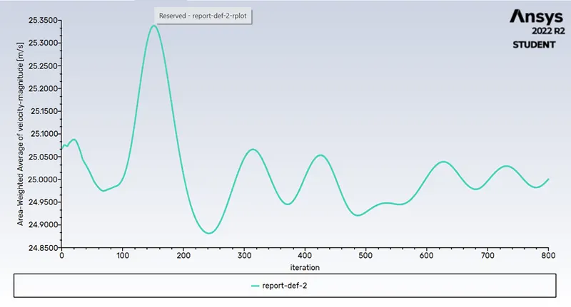
Fig 1. Average velocity Y+4
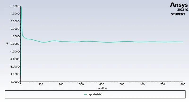
Fig 2. Coefficient drag for Y+4
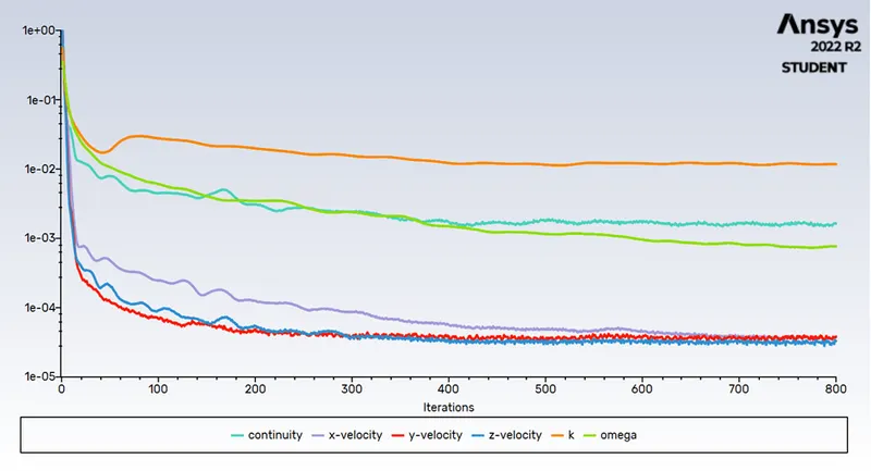
Fig 3. Scaled residuals for Y+4
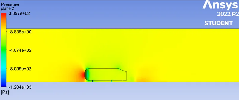
Fig 4. Pressure contour for Y+4
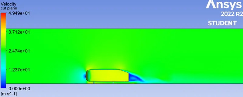
Fig 5. Velocity contour for y+4
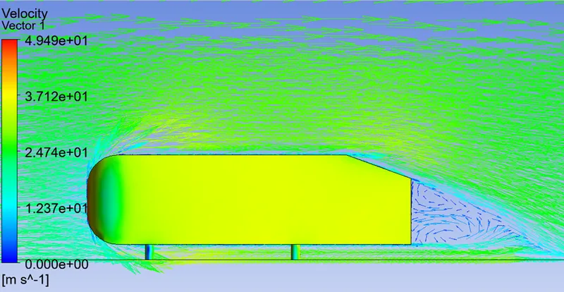
Fig 6. Velocity vector lines for y+4
- Case 2 where the Y+ value is between 30 – 300:
mesh elements = 489171
nodes= 105890
Reynolds number = 6.6e+5
Estimated Y+ value for 50 = 6.7e-4
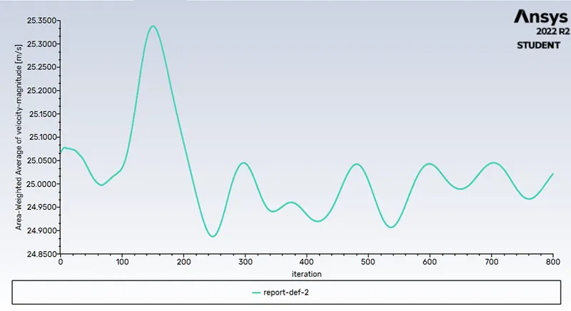
Fig 7. Velocity average
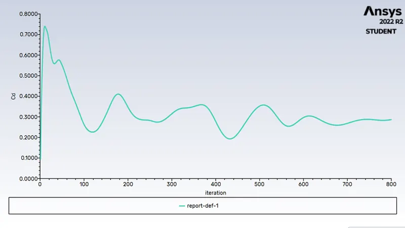
Fig 8. Coefficient drag
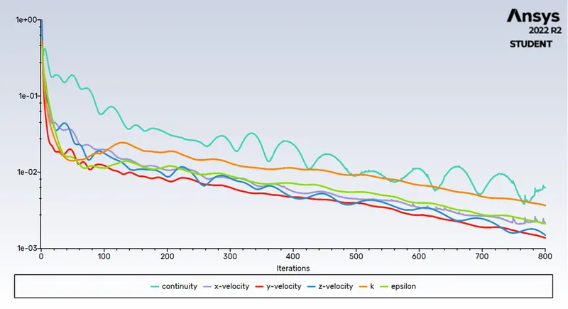
Fig 9. Scaled residuals
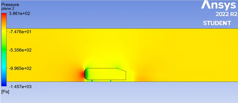
Fig 10. Pressure contour
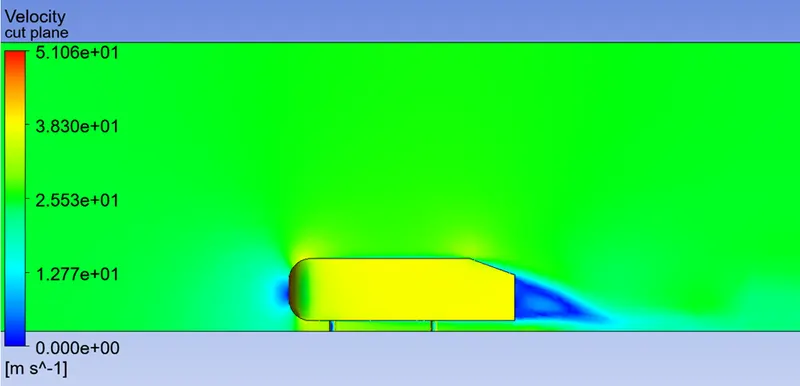
Fig 11. Velocity contour
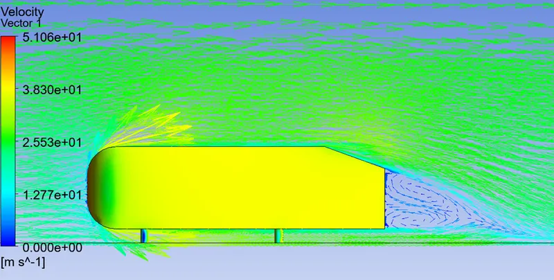
Fig 12. Velocity Vector lines
In fig we can see behind the ahmed body there was a wake region the vortices are formed there which is due to the flow clearly face the fluid exactly along the line of its frontal area side so flow will be strike on frontal are of body and diverts flow at up side and some at down side and the part behind ahmed body have near about zero velocity. As the wake area is reduced the drag causing eddies , generated due to pressure difference between the top and bottom of ahmed body at the rear tailing end , come closer together this result in less kinetic energy being dissipated due to these smaller eddies and consequently less compensation power required by engine to propel vehicle forward
The air becomes almost stagnant as it strikes the vehicle which results in air exerting very high pressure on front engine grill of the vehicle represented by the red area. The air flow then gets diverged between upper and lower surface of body. The high pressure air on front surface accelerates as it travels over the curved nose surface of ahmed body causing the pressure dop. This lower pressure creates lift over the roof surface as the air passes over it as the air continues to flow and make its way to rear the notch owing to flow over separation
Grid independency test :
|
Element size |
Number of nodes |
Number of elements |
Velocity |
Drag |
Error |
|
40mm |
44173 |
150405 |
25.000245 m/s |
0.31067331 |
0.01931 |
|
35mm |
52299 |
195481 |
24.990834 m/s |
0.37992134 |
-0.0499 |
|
30mm |
67817 |
279119 |
25.019094 m/s |
0.28338723 |
0.04662 |
|
25mm |
97950 |
442594 |
25.009559 m/s |
0.29186102 |
0.03841 |
|
23.9mm (most refined and final mesh) |
107387 |
496751 |
25.021589 |
0.28658168 |
0.0435 |
Conclusion :
- In conclusion first of all from mesh study we get to know that as we reduce the element size and refines the mesh the accuracy of problem increase and we get more clear about the simulation.
- According to y+ values of Reynolds number varies and according to those Reynolds number and Y+ values we have to select the model for the problem may be it will be k-epsilon or might k-omega
- Flow circulation takes place at the rear of vehicle / ahmed body or we can say the wake region is formed at the tail of ahmed body.