Week - 3 Drop test Challenge
AIM: To create the simulation of falling of mobile on the ground using proper input.
KEYWORDS: Contact energy, Hourglass, Contact, Boundary condition, Materials, Section, Initial Velocity, etc.,
SOFTWARE: LS-Dyna
OBJECTIVE:
- For the given meshed model check for the number of parts and rename accordingly.
- Creating suitable keywords like Material (Rigid & M24), Contact (Surface - Surface), Boundary condition (Rigid material), Section (Shell & Solid) & Control cards.
- Initial Velocity is given for the mobile part as 10 m/s.
- After creating the keywords, check for the model and save the keyword file.
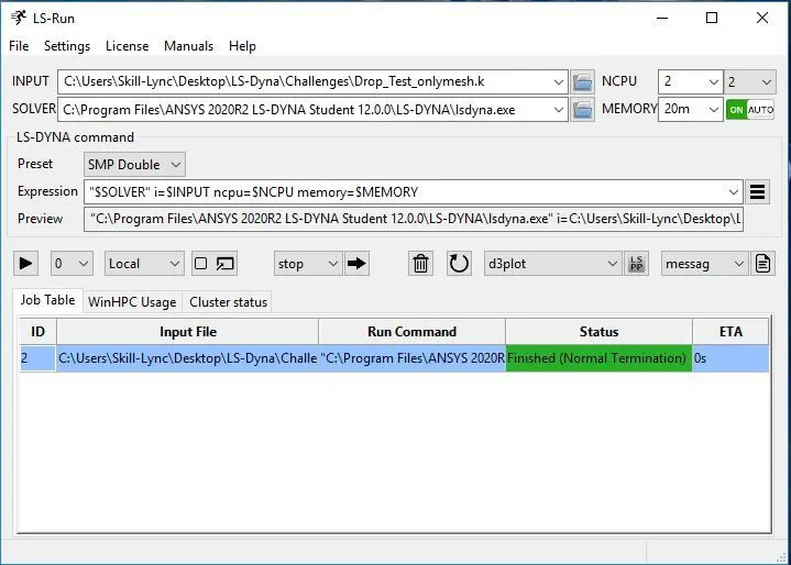
- Run the keyword file in LS-run and simulate.
- In the simulation, get the contour plot of Von-Moses stress and Effective strain.
- Plot all the energies (Kinetic, Internal, Total, Hourglass & Sliding) vs. Time (s).
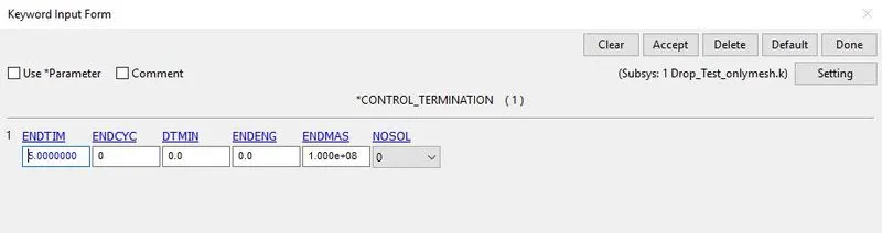
- The total termination time is given as 5ms.
INTRODUCTION:
Ansys LS-DYNA is the most commonly used explicit simulation program, capable of simulating the response of materials to short periods of severe loading. Its many elements, contact formulations, material models, and other controls can be used to simulate complex models with control over all the details of the problem. Ansys LS-DYNA has a vast array of capabilities to simulate extreme deformation problems using its explicit solver. Engineers can tackle simulations involving material failure and look at how the failure progresses through a part or through a system. Models with large amounts of parts or surfaces interacting with each other are also easily handled, and the interactions and load passing between complex behaviors are modeled accurately. Using computers with higher numbers of CPU cores can drastically reduce solution times. LS-DYNA consists of a single executable file and is entirely command-line driven. Therefore, all that is required to run LS-DYNA is a command shell, the executable, an input file, and enough free disk space to run the calculation. All input files are in a simple ASCII format and thus can be prepared using any text editor. Input files can also be prepared with the aid of a graphical preprocessor. There are many third-party software products available for preprocessing LS-DYNA input files.
Here, The given model has already meshed for shell and solid components which as to be simulated by performing the drop test of a cellphone on the ground by giving an initial velocity of 10 m/s. The actual geometry along with mesh which is shown below figure,
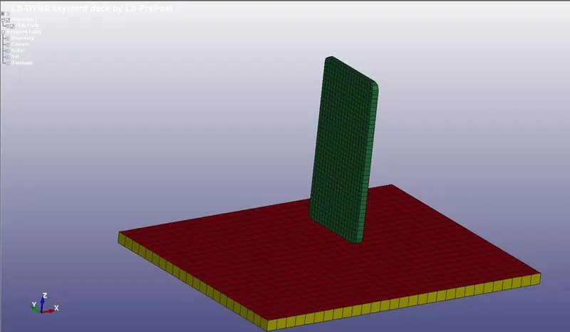
Figure 1: Meshed parts
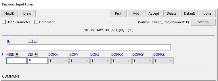
Here, the base part is constrained in all directions and the cell phone is constrained except in the vertical direction which allows falling freely on the ground.
Boundary_condition for the base part: Here, the base part is constrained in all directions.
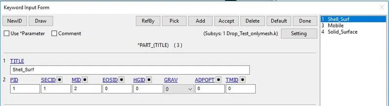
Parts_definition: By assigning the section and material id for the respective shell and solid parts.
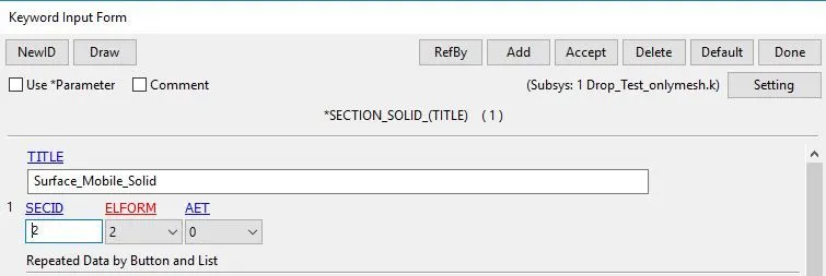
Section_definition for Shell: Here, Defining Element formulation (ELFORM-2), number of integration points, and thickness for the particular part.
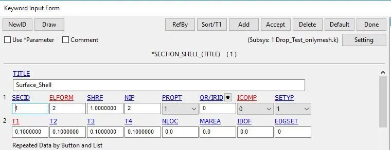
ELFORM=2 (default element)-Belytschko-Lin-Tsay shell formulation
- Based on Reissner-Mindlin kinematic assumption (5 DOF in local coordinate system yield globally 6 DOF)
- Extremely effective: Formulated in velocity strains (rate of deformations) and Cauchy stresses.
- Bi-linear nodal interpolation
- One-point integration for efficiency reasons
- Updated, co-rotational Lagrangean formulation
- Hourglass control to counterbalance zero-energy modes
- warping stiffness (BWC flag on *CONTROL_SHELL)
- Warpage may be an issue; do not use in coarse models
- Nodal fiber vectors for improved warping stiffness
- Fastest kid in town but does not pass the patch test
Section_definition for Solid:
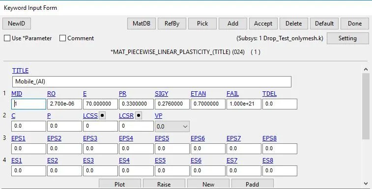
Material_definition for Cellphone part: Here, the material is preferred as Aluminium and assigned all the parameters like density, young's modulus, Poisson ratio, and Yield stress, etc.,
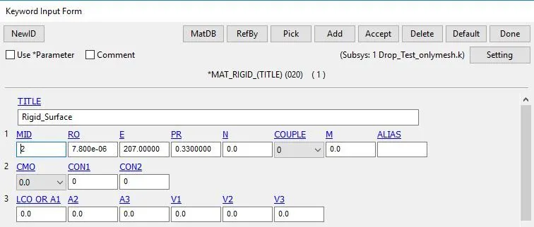
Material_definition for Rigid (Base) part: Here, the material is preferred as Steel and assigned all the parameters like density, young's modulus, Poisson ratio, and Yield stress, etc.,
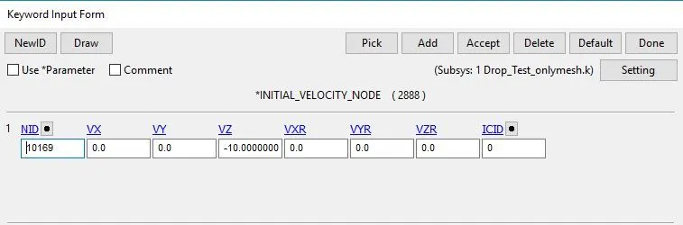
Initial velocity for the cell phone part: Here, the velocity is defined as 10m/s in z-direction for the cell part
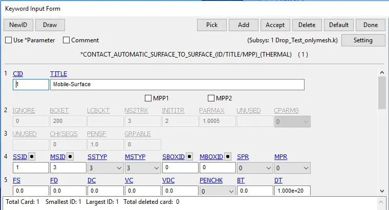
Contact Surface to Surface definition: Here, The mobile part is considered as slave type and the base part is considered as a master (rigid) type.
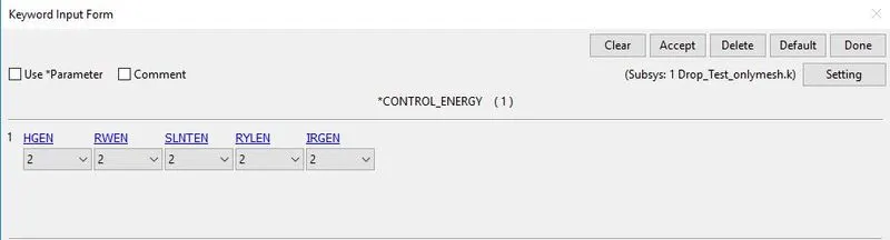
Control_energy definition: Here, Hourglass energy, stone wall energy, sliding energy, rayleigh energy, and initial reference energy are considered for energy balance.
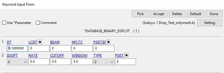
Binary_D3Plot_Definition: Here, the time interval between the outputs is defined (DT)
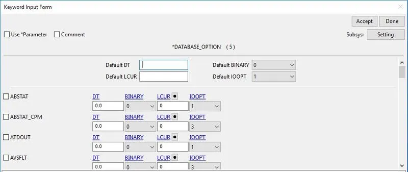
ASCII_Option: Here, ELOUT, GLSTAT, NODOUT, MATSUM, and SLEOUT are defined.
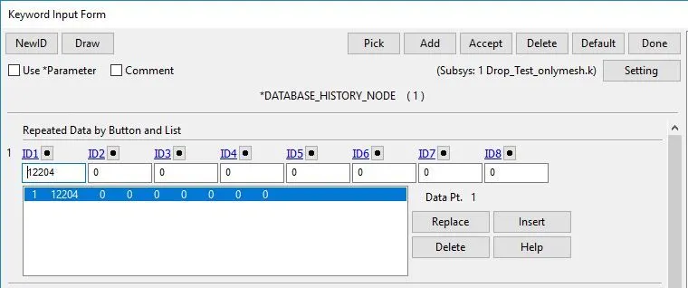
History_Node_Definition: Here, selecting one of the nodes in the mobile part to plot the acceleration and force acting in the z-direction.
Control_Termination: Here, the termination time is given as 5ms.
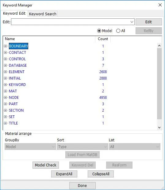
Keyword_Manager: Here, the required keywords are assigned and listed.
LS-Run: Here, the file imported and run the simulation, after the simulation plot the effective stress and strain.
RESULTS:
(I) PLOT ENERGY VS. TIME:
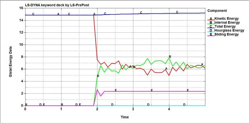
The above plots show the energy involved in the energy balance and how those energies are utilized or consumed by the simulation. At the time 2ms, the kinetic energy is reduced and internal energy is increased when the cellphone comes into contact with the rigid surface. There is no hourglass energy formed because of fully integrated.
(II) PLOT VELOCITY VS. TIME:
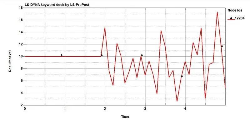
The above plot shows the velocity variation against time. when the cellphone gets into contact with a rigid surface the velocity of a cell phone part varies accordingly. By selecting one of the nodes in the cellphone part and added to the node history and get the result.
(III) CONTOUR PLOT OF EFFECTIVE STRAIN:
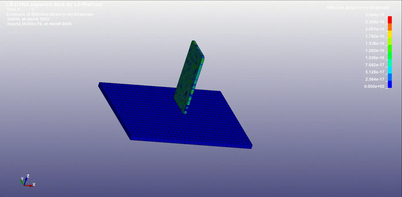
Due to the impact, the max effective strain developed in the cellphone part is 0.014 % which is deformed plastically. The material used for the cellphone part is Aluminium and related parameters are assigned.
(III) CONTOUR PLOT OF VON-MISES STRESS:
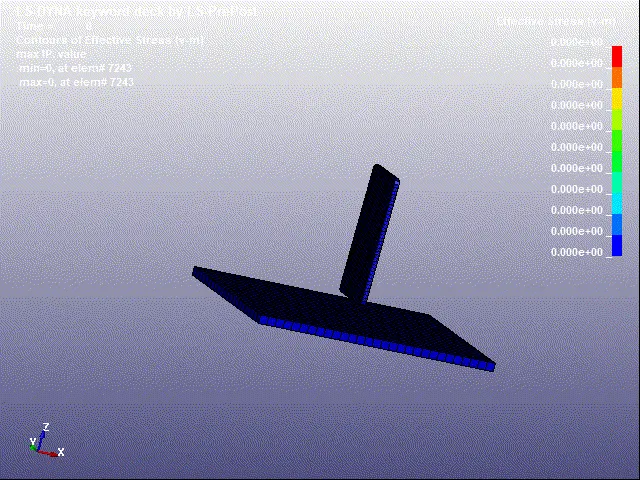
Due to the impact, the max von mises stress developed in the cellphone part is 0.123 N/m2 which is formed at the tip of the cell phone part.
CONCLUSION:
The cellphone part is assigned as Aluminium (M-024) and the Base part is assigned as Steel (Rigid_M-020).
The initial velocity given for the Aluminium part is 10m/s.
When the cellphone part is falling freely at a velocity of 10 m/s in z-direction towards the ground.
The max von misses stress is developed at the tip is 0.123 N/m2 and max effective strain developed is 0.014 % deformed.