Week - 3 Drop test Challenge
Objective:- Drop Test conducted on Cellphone in LS DYNA with creating all the necessary keywords starting from
- Material for Rigid wall and cellphone
- Section creation
- Assigning material and section to their respective parts
- Creating Boundary condition for rigid wall
- Giving intial velocity to Cellphone
- Creating contact between cellphone and rigid wall
- Creating control cards for simulation
- Requesting Outputs for simulation
- Plotting the results
The drop test conducted for this simulation follows Military Standard (MIL-STD-810G) in which the drop test is conducted with distance of 1800 mm between cellphone and rigid wall . Material of cellphone is selected Aluminium alloy 3003
Model:-
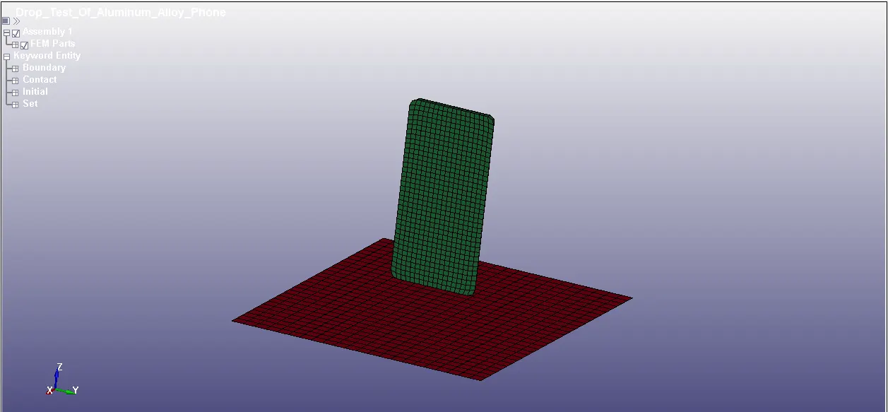
Model of Cellphone with rigid wall plate
Section:-
There are two sections in the model for plate SHELL with ELFORM-2 is used while for cellphone SOLID ELFORM-1
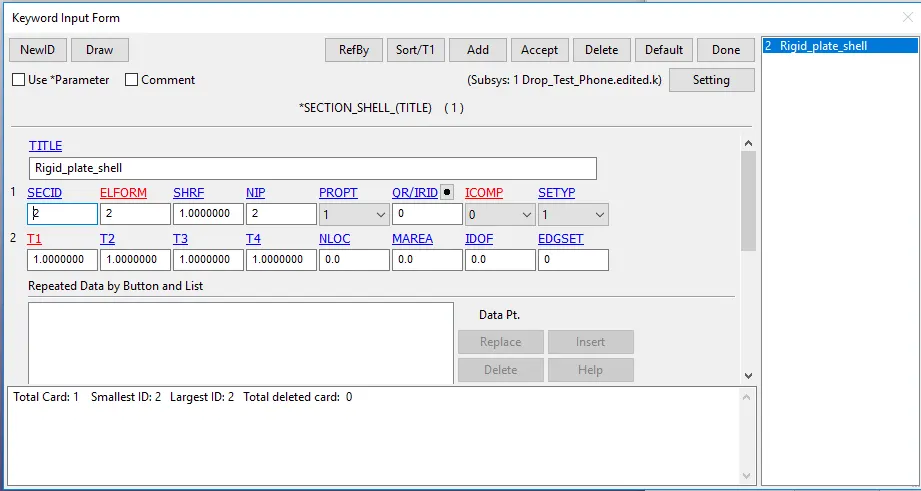
Section SHELL for Rigid plate
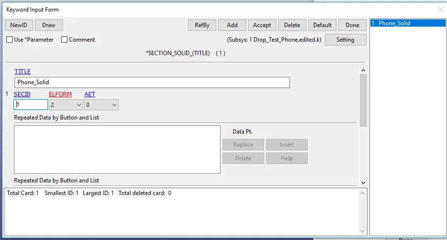
Section SOLID for Cellphone
Materials:-
For Rigid plate MAT_20_Rigid is assigned while for Cellphone MAT_24_Piecewise_Linear_Plasticity with properties of Aluminium alloy 3003 is alloted
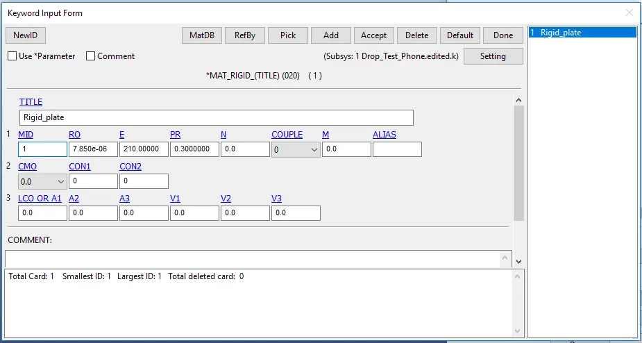
MAT_20_RIGID for Rigid plate
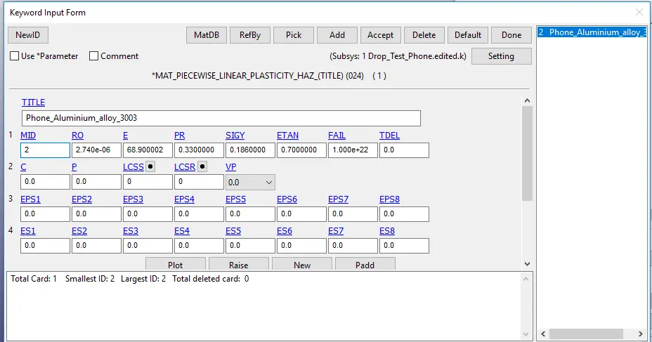
MAT_24_Piecewise_linear_plasticity for Cellphone
Parts:-
In parts , we basically assign material and section with their proper ID for every part individually
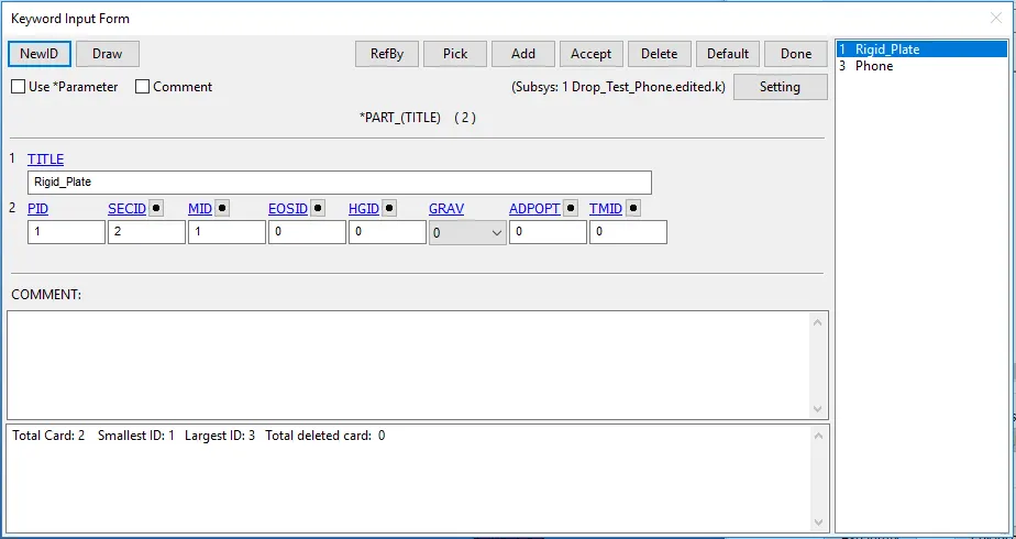
SECID and MID assigned to Rigid plate
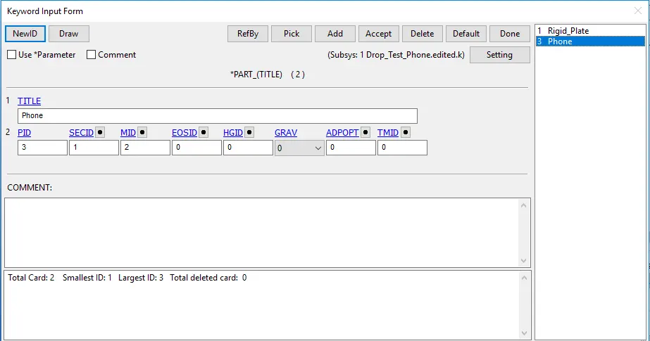
SECID and MID assigned to Cellphone
Boundary conditions:-
The unit system followed is 'kg-mm-ms-J-KN-GPa' . We create an Single point Constrained SPC set by fixing all the edges of the rigid plate in all DOFs.
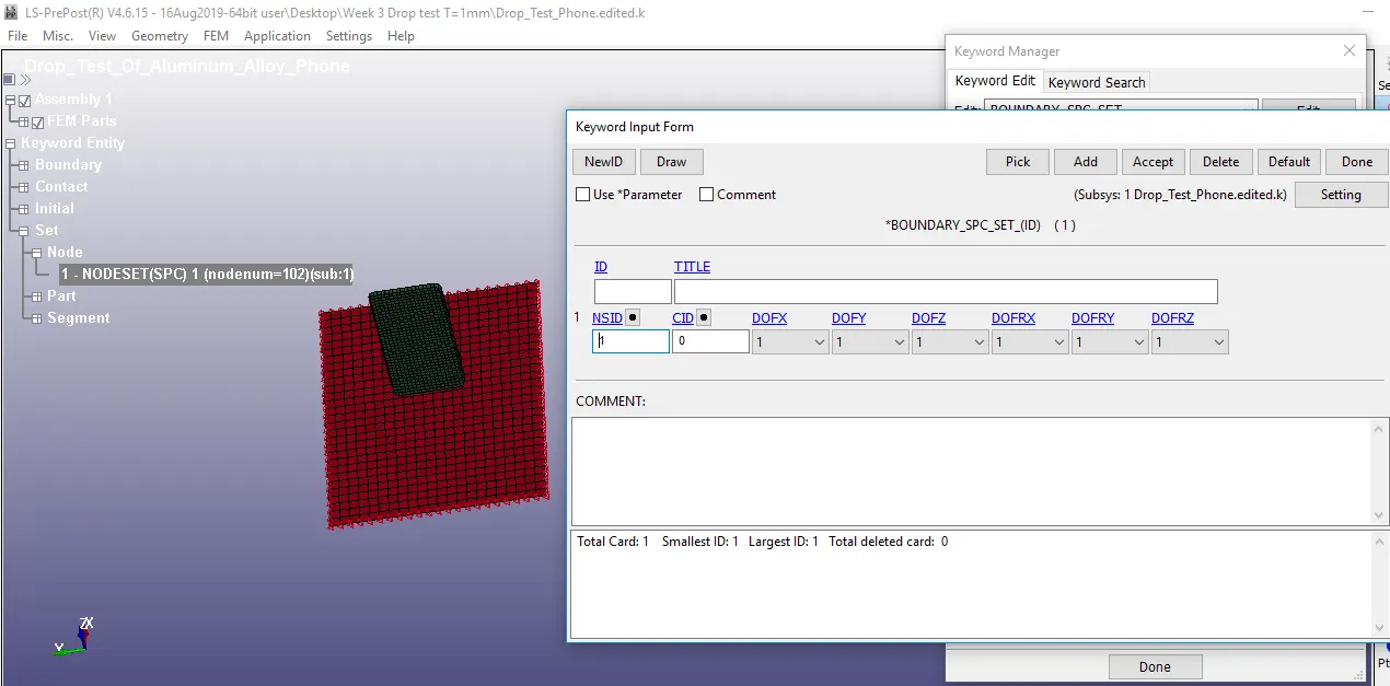
Boundary_SPC_set on all four edges of rigid plate
In order to provide motion of our cellphone , Initial velocity is given on it to so that it can fall or drop of rigid plate. Since the distance between Cellphone and plate is around 20 mm so velocity `v=sqrt(2xxgxxh)` is used as the simulation is of drop test. `v=sqrt(2xx0.00981xx20)` which is approximately equals to 0.629 mm/ms . As the value of velocity is very less so it will take alot of time to have impact with rigid plate which will increase computational cost as we want to have 5 ms as our end time for simulation. So we will use actual condition of military cellphone drop which occurs at distance of 1800 mm. Velocity calculated from this around 5.94 mm/ms. As cellphone is dropping along negative z direction so Vz= -5.94 mm/ms is given as initial velocity by selecting all the nodes of cellphone.
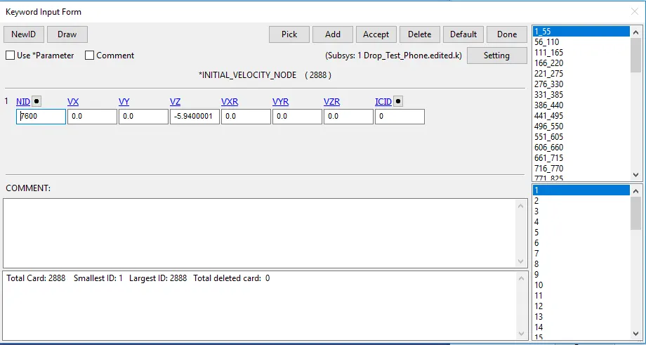
Initial_velocity given to cellphone
Contact:-
Contact_Automatic_Surface_to_Surface is given between Cellphone and Rigid plate . Selection of slave and master is done on decision of material , thickness ,etc . As in our case cellphone is softer as compare to rigid plate so Cellphone is assigned as Slave and Rigid plate as Master.
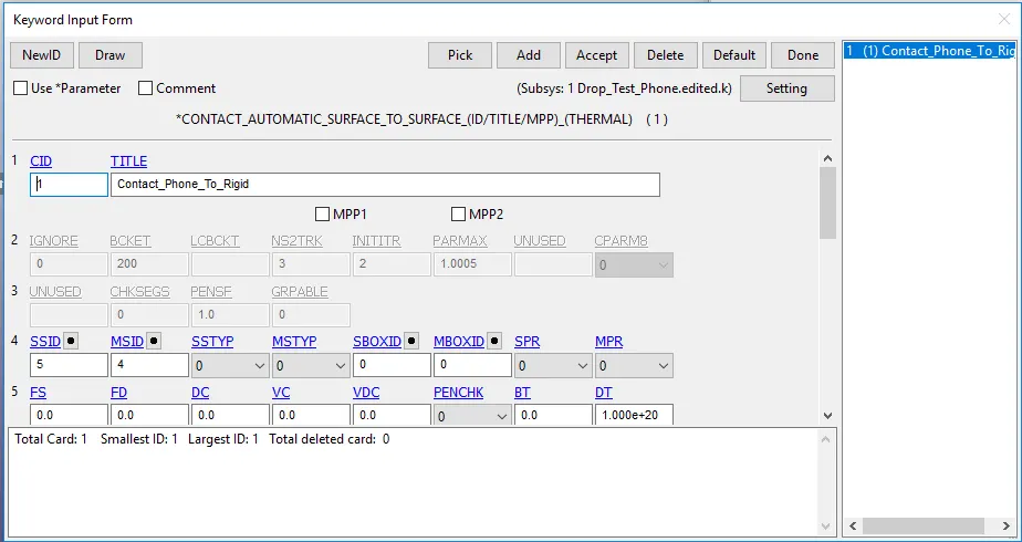
Contact between cellphone and rigid plate
Control_Cards:-
Control_Energy card is used so that hourglass energy can be controlled. Control_Termination is used to provide end time to solution which in our case is 5 ms
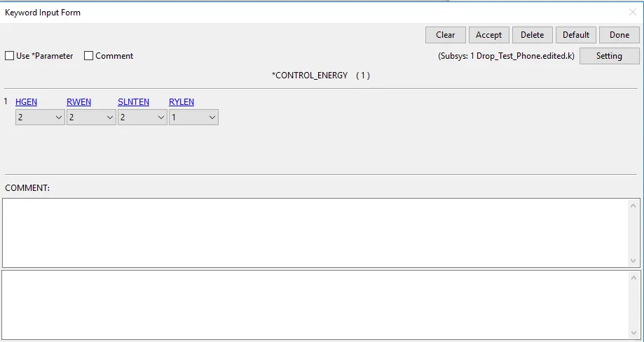
Control_Energy_Card
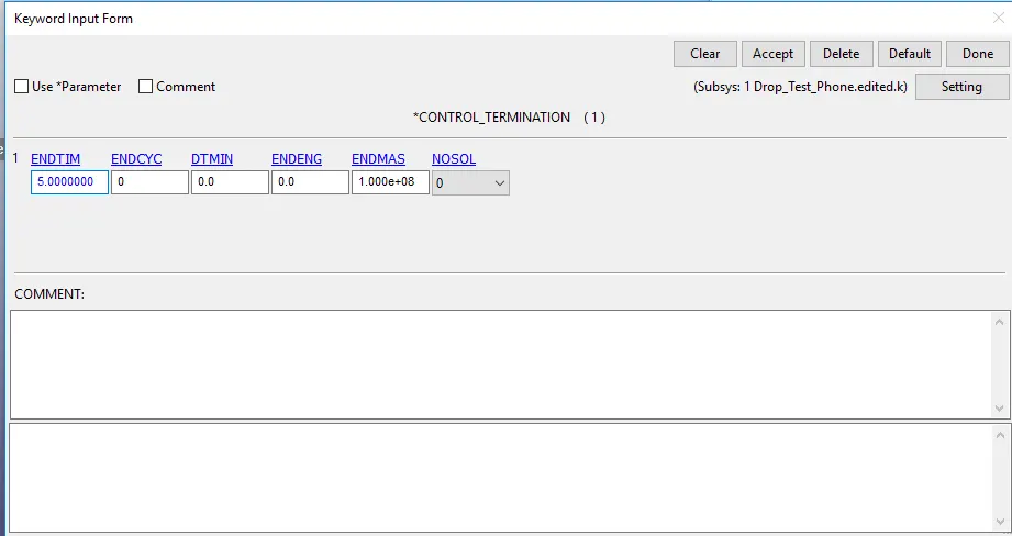
Control_Termination_Card
Solution Output:-
Animation of Simulation:-
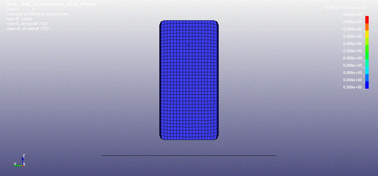
Drop test of Cellphone on Rigid plate
From simulation we can see that , from 0 ms till 3.199 ms the impact doesnt happens but at 3.2 ms impact happens and after impact with rigid plate the cellphone rebounds and tries to comeback at it initial position at 5 ms
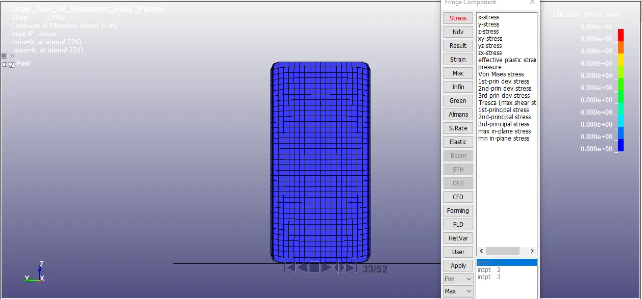
Von mises stress at 33th frame
It can seen that impact doesnt take place till 33th frame or 3.1997 ms so the von-mises stress developed on cellphone is 0 GPa
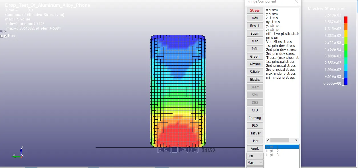
Von mises stress at 34th frame
It can seen that impact take place at 34th frame or 3.3 ms so the von-mises stress developed on cellphone will be maximum at point of impact is 0.0951882 GPa
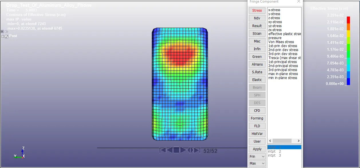
Von mises stress at 52th frame
It can seen that impact doesnt take place at the end 33th frame or 5 ms so the von-mises stress develpoed on cellphone is 0.0235138 GPa
From the stress plot , we can observe that the maximum expected von-mises stress will be obtained at the point of impact of cellphone with rigid plate which is 0.0951882 GPa. As phone suffers the plastic deformation there will be stress developed at the point where kinetic energy is converted to internal energy of the component and the top region which doesnt come in contact during impact the stress obtained is zero.
GLSTAT plot:-
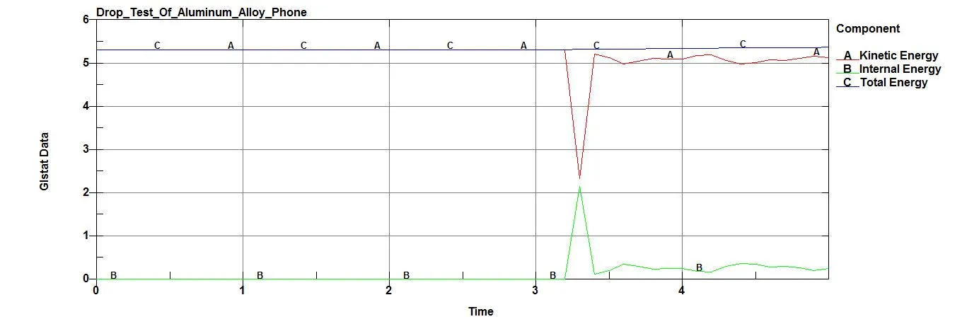
Plot of K.E , I.E and T.E of simulation
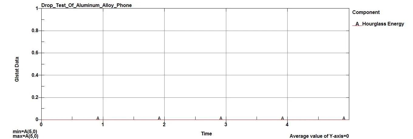
Plot of Hourglass energy of simulation
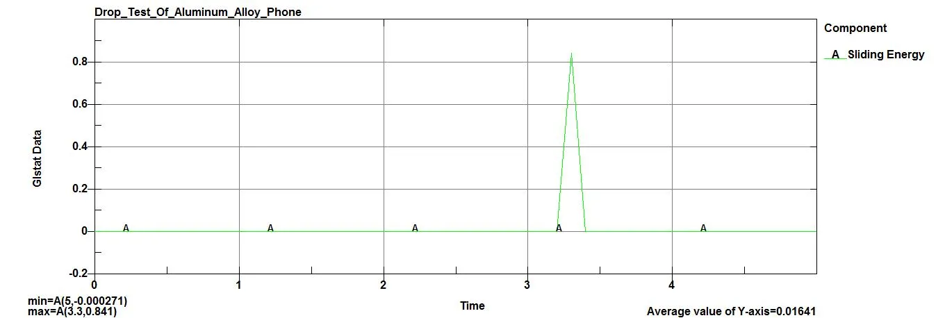
Plot of Sliding energy of simulation
GLSTAT is use for generating Global energy developed during analysis.
Impact time obatined from simulation is 3.2-3.4 ms during this time impact happens of cellphone with rigid plate and then it starts to rebound back.
At 3.2 ms
Internal energy = 2.e-20 J,Kinetic energy = 5.32 J,Total energy = 5.37 J,Sliding Energy = 0 J,Hourglass energy = 0 J
At 5 ms
Internal energy = 0.242 J,Kinetic energy = 5.13 J,Total energy = 5.32 J,Sliding Energy = 0 J,Hourglass energy = 0 J
Here we can see from the plot that as law of conservation of energy states that total energy of simulation remains constant. As the mobile phone cames down the only kinetic energy is with phone as the ground is rigid.So the kinetic energy of phone will be reduced as soon as the phone hits the ground at the time equals 3.2 millisecond and the lost kinetic energy is getting converted into the internal energy of the component as the material will gets deformed by absorbing some little amount of energy. Since we use the hourglass control card and good element formulation for the elements in the model the hourglass energy is nearly equals to zero.So simulation results makes sense.
MATSUM plot:-
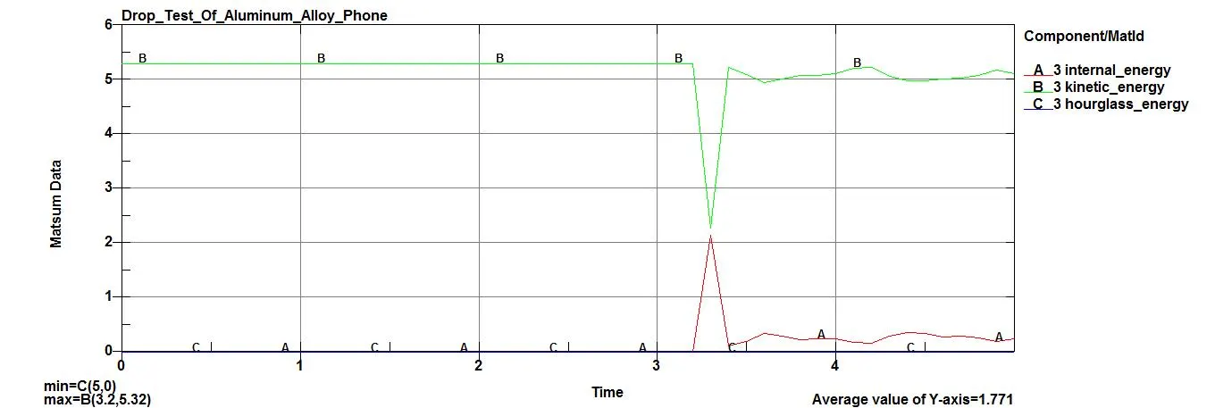
MATSUM Plot of I.E , K.E , Hourglass energy
MATSUM is used to generate Material energies.
This plot shows plastic deformation taking place at impact by obeying law of conservation of energy we can see that as soon as impact happens kinetic energy falls rapidly at the same time internal energy increases rapidly to its peak. Since impact happens in 3.2-3.4 ms value of kinetic energy at its peak is 2.28 J while that of internal energy is 2.16 J at its peak. Hourglass energy obtained in simulation is 0 J.
Conclusion :-
From the simulation we get to see the process of setting up of the solver deck for the drop test of the cellphone. When an impact happens the maximum stress will be devoloped at the time of impact,that small miliseconds lasting duration will cause the maximum stress and strain happens to the object which makes the impact.After the impact there will be some KE left with the object later the conversion to internal energy, so with that the object will be rebounds back. If the crash is very rapid like the entire kinetic energy is getting fully converted into internal energy by the huge deformation affected to the componenet then there will be minimal rebounce after the impact and that may not be visible to eyes.