Week - 3 Drop test Challenge
OBJECTIVE: -
The objective of this assignment is not to get a correct simulation but to get a feel of creating an input deck from scratch. I have been provided with a mesh file and a complete simulation of the drop test is made and analysed below.
PROCEDURE: -
<!-- [if !supportLists]-->Ø <!--[endif]-->IMPORT THE MODEL
<!-- [if !supportLists]-->· <!--[endif]-->Open LS-Dyna program manager and click on LS – Pre post.
<!-- [if !supportLists]-->· <!--[endif]-->Go to File – Open – LS DYNA and Import the K. file in LS Pre-Post and it solved by LS-Dyna.
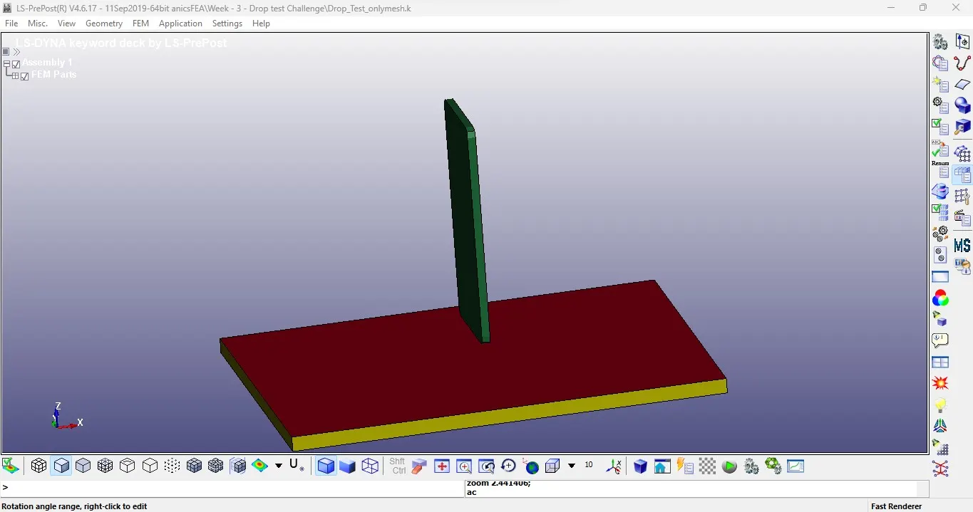
<!-- [if !supportLists]-->· <!--[endif]-->Given model consists of three parts
<!-- [if !supportLists]-->§ <!--[endif]-->Cell phone
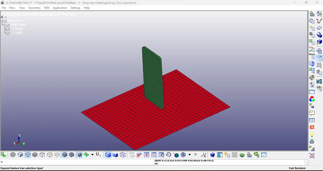
<!-- [if !supportLists]-->§ <!--[endif]-->One floor made of shell element and
<!-- [if !supportLists]-->§ <!--[endif]-->One floor made of solid element
<!-- [if !supportLists]-->· <!--[endif]-->Here we need one ground only. So, delete the solid part.
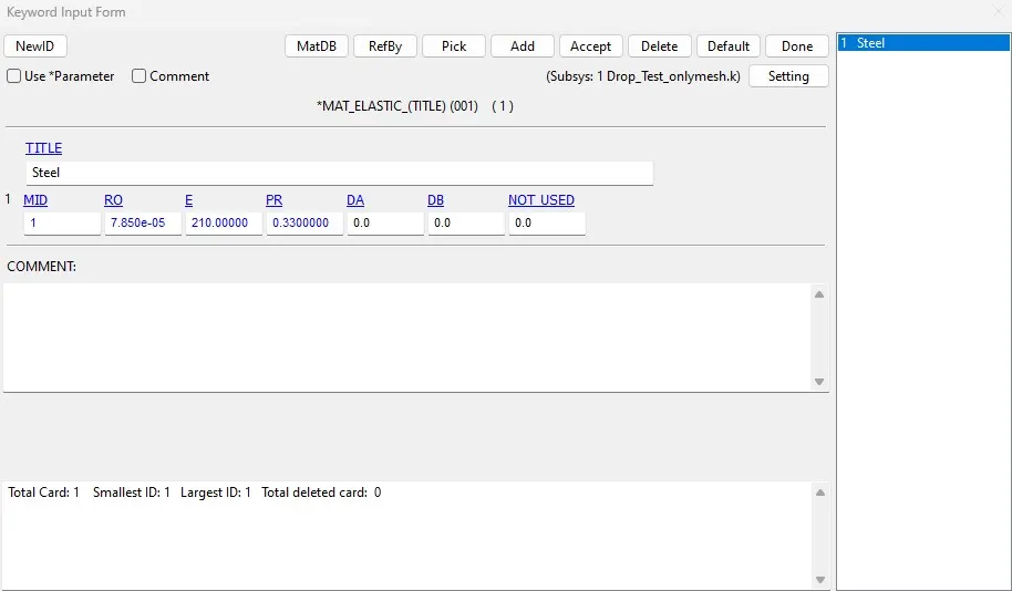
<!-- [if !supportLists]-->· <!--[endif]-->Now create the material cards for both the parts. Take the different materials for Aluminium for phone and steel for ground.
<!-- [if !supportLists]-->· <!--[endif]-->To create material card, go to keyword manager – select all – mat – 024 piecewise linear plasticity.
<!-- [if !supportLists]-->· <!--[endif]-->Enter the necessary input for material card and select apply.
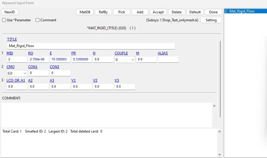
<!-- [if !supportLists]-->· <!--[endif]-->Create material card for wall, follow the same procedure.
<!-- [if !supportLists]-->· <!--[endif]-->After create the material for parts. Let’s create section for that.
<!-- [if !supportLists]-->Ø <!--[endif]-->SECTION
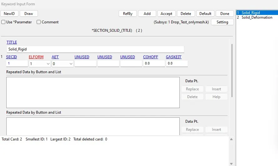
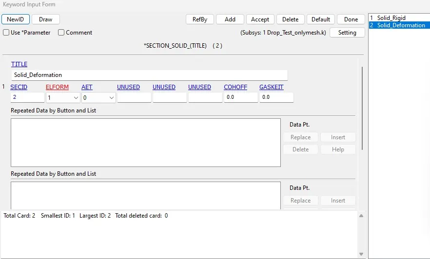
<!-- [if !supportLists]-->· <!--[endif]-->Create section for wall & phone. Go to keyword manager – Section for shell & solid.
<!-- [if !supportLists]-->Ø <!--[endif]-->PART
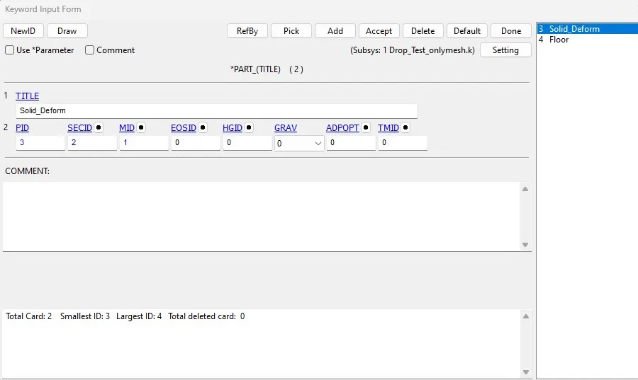
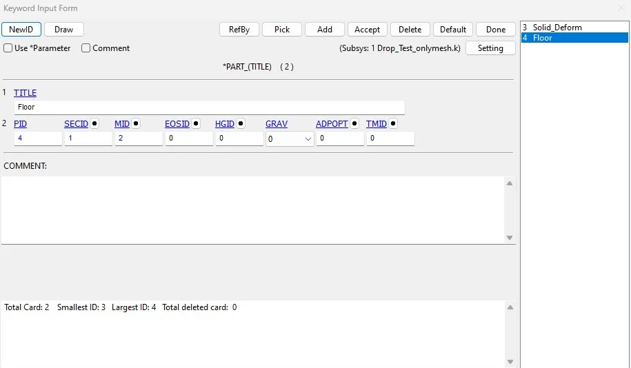
<!-- [if !supportLists]-->· <!--[endif]-->The part keyword is opened and section, material and PID is assigned to their respective parts as seen below
<!-- [if !supportLists]-->Ø <!--[endif]-->BOUNDARY
<!-- [if !supportLists]-->· <!--[endif]-->The nodes on the edges of the wall are selected to be fixed in all DOFs. An SPC set is created.
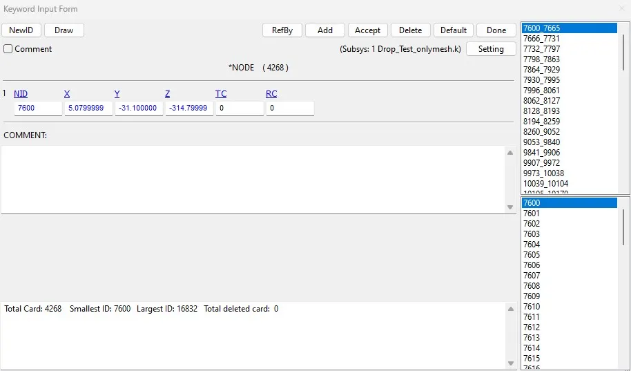
<!-- [if !supportLists]-->· <!--[endif]-->A part list is created to highlight the nodes on each of the part. The solid and shell parts are created separately.
<!-- [if !supportLists]-->Ø <!--[endif]-->CONTACT
<!-- [if !supportLists]-->· <!--[endif]-->A contact is defined from the contact keyword. Contact automatic surface to surface is used.
<!-- [if !supportLists]-->· <!--[endif]-->SSTYPE and MSTYPE is placed on the number 2 to allow the possibility to assign parts as master and slave. SSID and MSID are assigned by making the phone the slave and wall the master.
<!-- [if !supportLists]-->Ø <!--[endif]-->INTIAL VELOCITY
<!-- [if !supportLists]-->· <!--[endif]-->The orientation of the phone is ignored as this is just a demonstrational exercise.
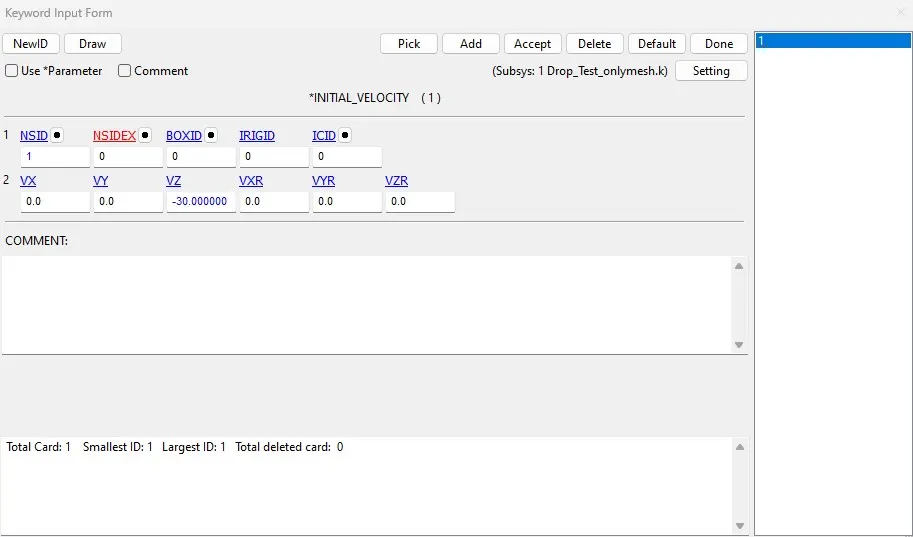
<!-- [if !supportLists]-->· <!--[endif]-->The initial velocity of free fall is assumed to be 5mm/ms. This is assigned to the phone using the part node set and specified in the negative Z direction.
<!-- [if !supportLists]-->Ø <!--[endif]-->CONTROL TERMINATION
<!-- [if !supportLists]-->· <!--[endif]-->This keyword controls the end time of the simulation. DT is specified to 5ms.
<!-- [if !supportLists]-->Ø <!--[endif]-->OUTPUT
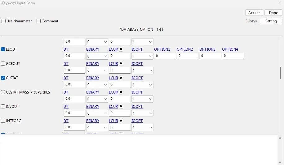
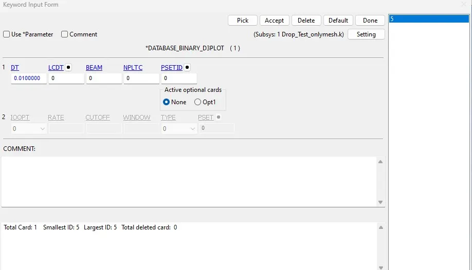
<!-- [if !supportLists]-->· <!--[endif]-->Output files are requested using database keyword. D3plot is requested with a time of 0.5ms. Similarly, we request for ELOUT, GLSAT, and MATSUM is requested to be analysed.
POST-PROCESSING: -
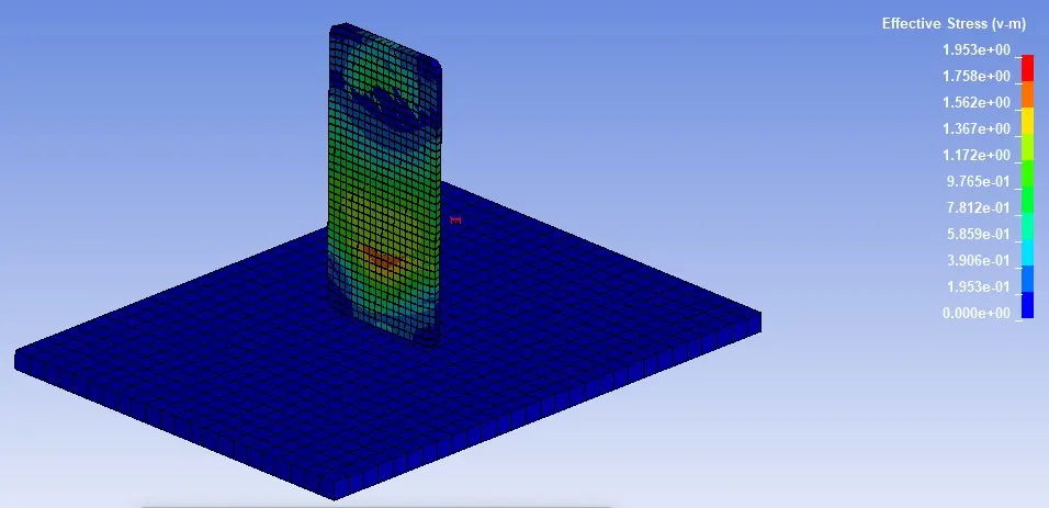
The following figure below shows the von-mises stress induced during the drop test which shows that high stresses are induced at the bottom of the cell phone.
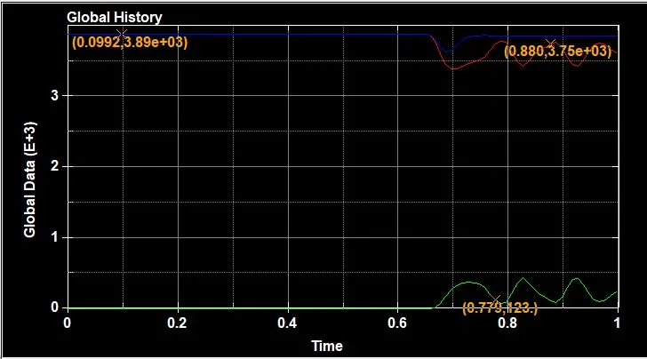
The graph shows the kinetic energy, internal energy results after running the file.
RESULT: -
A complete simulation for a drop test was done from the given mesh model of a cell phone dropping on the floor. This simulation helps how to create contact and termination time, mainly how to given inputs to run the model.