Week - 3 Drop test Challenge
Objective:
To perform the drop test of Mobile phone on solid ground by setting the CAD model with mesh, using the Lsdyna setting the velocity of the phone along with animation and plotting the necessary graph.
Procedure:
Importing the model keyword file after opening the LS Pre-post then setting the model as per the requirement.
File>Open > brows> drop test model .k
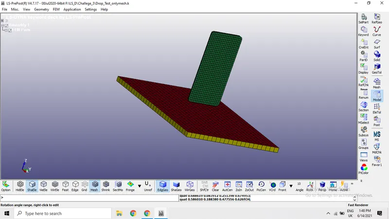
As we can see the image, the model with mesh position using the auto center option so that we can see the image properly. We consider mesh only in the setup so we can delete the solid in the model.
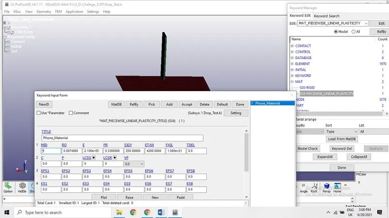
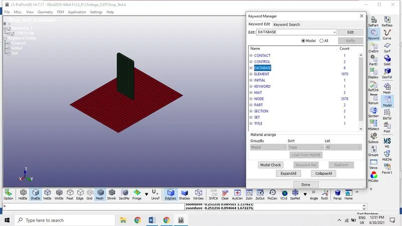
Now open the keyword manger by clicking on the model icon then assign the material by opening the keyword manger, open the MAT file to assign the material peroperty to the model from exiting materials. There are many material type available here but *MAT_024* is the piecewise Linear plasticity which is suitable for robust materials of linear plasticity also suitable for elastoplastic materials.(strain –rate dependency) Which is suitable for viscoelastic material behavior with arbitrary stress .
Keyword Manger > select MAT> 024-MAT, 020-MAT> keyword input form
MID: Material identification number
RO: mass density of the material
E: Young’s modules
PR: Poisson’s Ratio
SIGY: Yield Stress
ETAN: Tangent Modulus.
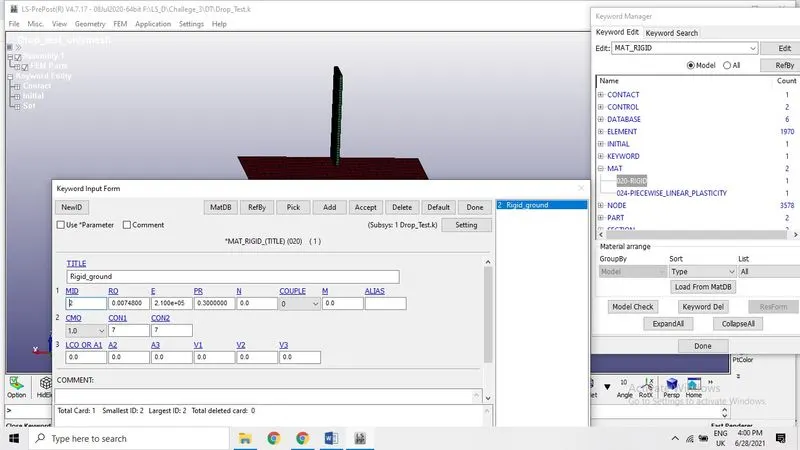
MAT_020 – Rigid _plate for ground material which is consider as a solid ground or plate and assigned the MAT_020 as Rigid part in the model. Where deformation and stress is not the important criteria.
Assigning Section:
Here we assign section properties of elements, we have section shell element and section sold elements, we consider the phone elements as solid elements and ground as section shell elements.
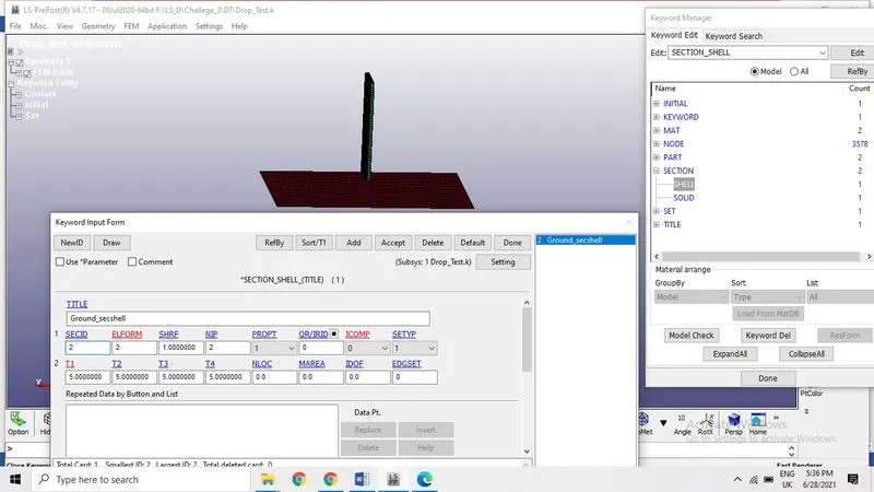
SECID: Section ID, SECID is reference ID on Part Card. A unique number must be specified
ELFORM: Element formulation, here we considered 2 which is fully integrated S/R intended solid elements with poor aspect ratio, accurate formulation.
Assigning the section and material to the part:
Here PID: Part ID, Assigning the respective part ID for each part and material ID
Contact Creation:
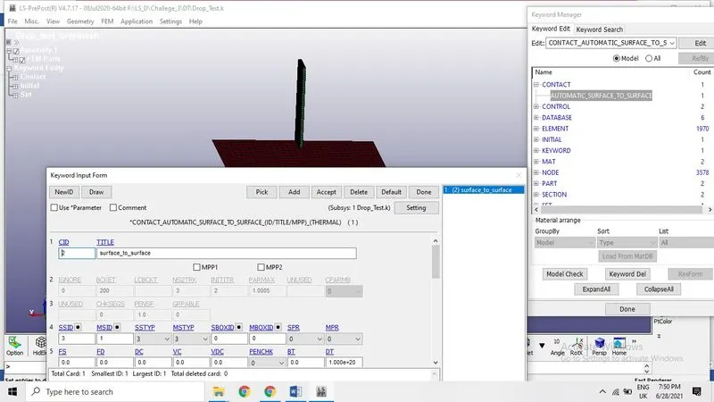
The mobile is dropped on to the floor, which is considered as ground here we need to create contact between grounds and object (phone) using two contact. Automatic surface to surface defined as master and slave contact, here we use mobile phone is created as slave type and ground as master type.
SSID: Slave Set ID, it is defined by the part type
MSID: Master Set ID, it is also defined by the Part type
SSTYP: Slave Set Type, it is selected according to the part.
MSTYP: Master Set Type, it is also selected according to the part
Boundary conditions:
Here we use Single point constraint is used on ground because it is fixed object that is why we lock the all degrees of freedom during simulation when the mobile phone fall on the ground. The value of 0 means DOF here is no constraints whereas 1 means the DOF is locked.
Initial velocity:
While mobile phone fall from certain height so we need to assume initial velocity as 10 mm/ms the phone in the negative direction of Z –axis
NSID: Node set ID, created for the ground where as Vx is the translation along the x-direction , VxR – rotational motion along the x –direction.
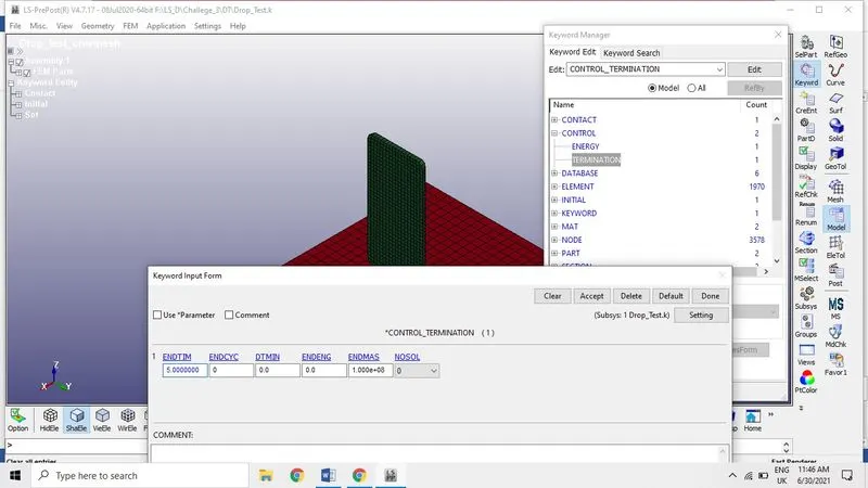
Control Termination
This is about termination of simulation time. Here we can give the simulation ENDTIME is set as 5ms.
Control _Energy: Controls energy dissipation in the simulation time
Control _Energy
HGEN: Hourglass energy calculation option.
RWEN: Stonewall energy dissipation option:
SLNTEN: Sliding interface energy dissipation option
RYLEN: Rayleigh energy dissipation option (damping energy dissipation)
IRGEN: Initial reference geometry energy option (included in internal energy, resulting from *INITIAL_FOAM_REFERENCE_GEOMETRY):
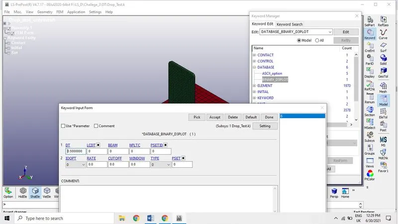
Database creation: Binary_D3PLOT is defined as frequency at which the animation file set to run , it is set as 0.5ms
DT: frequncy at which the animation file should be printed
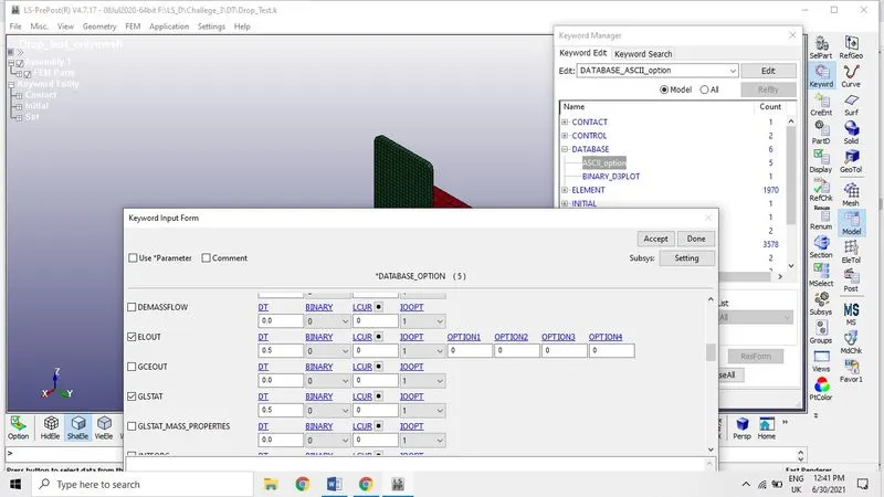
DATABASE _Option ASCII: The following options are activated in the ASCII Database to get the output in a required ASCII format.
ELOUT: Element Data
GLSTAT: Global Data
MATSUM: Material Energies
RCFORCE: Contact forces and rigid wall forces.
This the final keyword setup file now we can run the simulation.
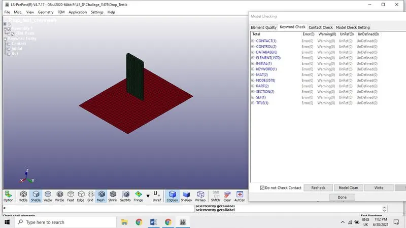
Model check is to verify any errors in the keyword input files, there is no error in the file so we can save this keyword before we run the simulation.

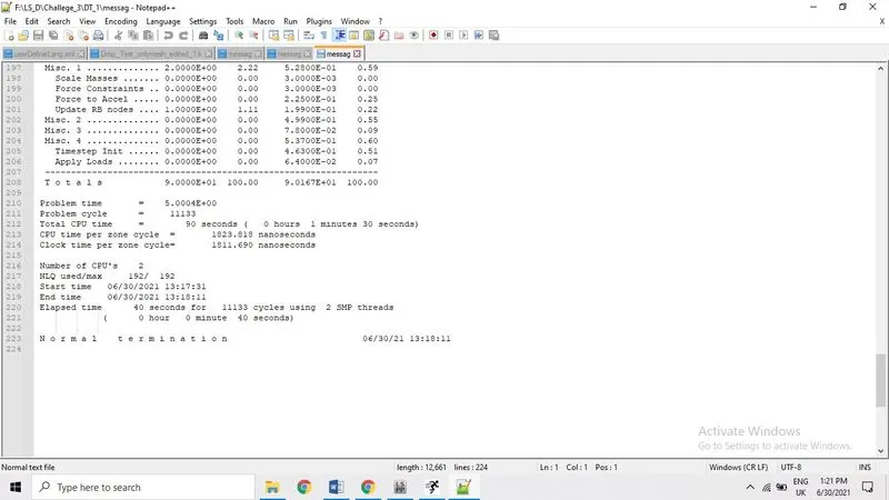
Animation: After running the file Ls pre-post shows that it is normal termination then open the file as binary plot.
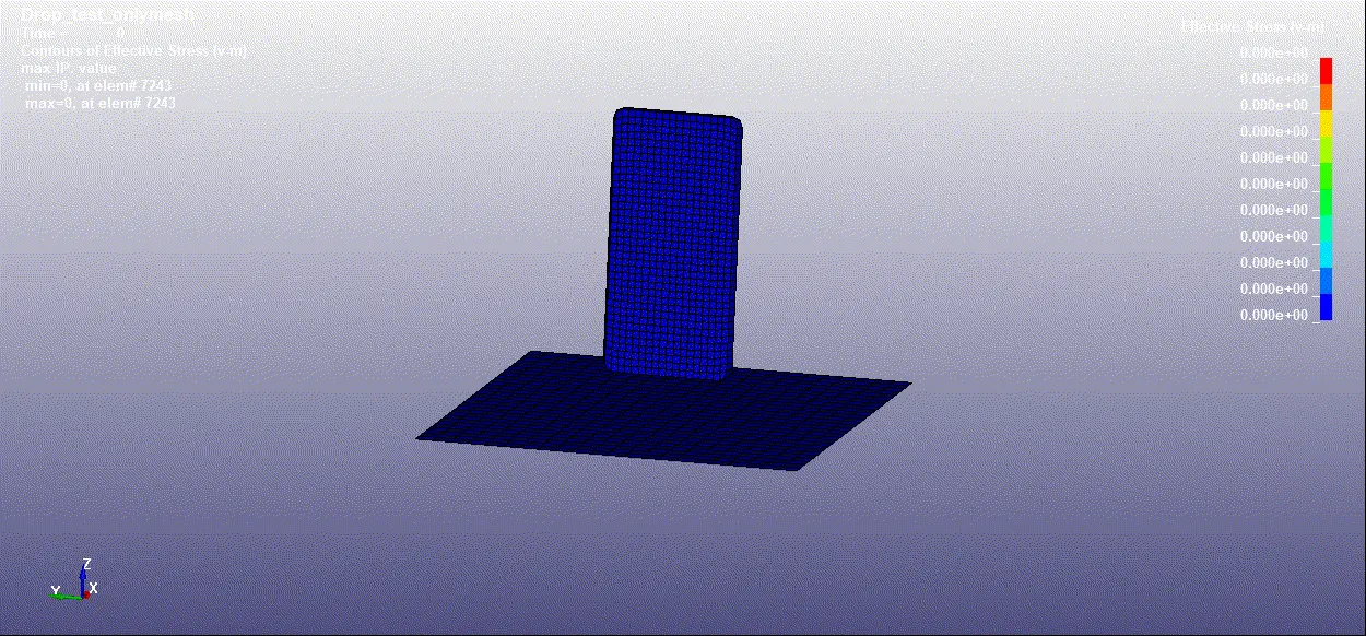
Effective stress (v-m) minimum that is zero at element no 7243 and maximum that is 78.4281 to be found at element no 5984
Effective Strain is zero at the element 7243 and maximum that is 0.08732 at 718
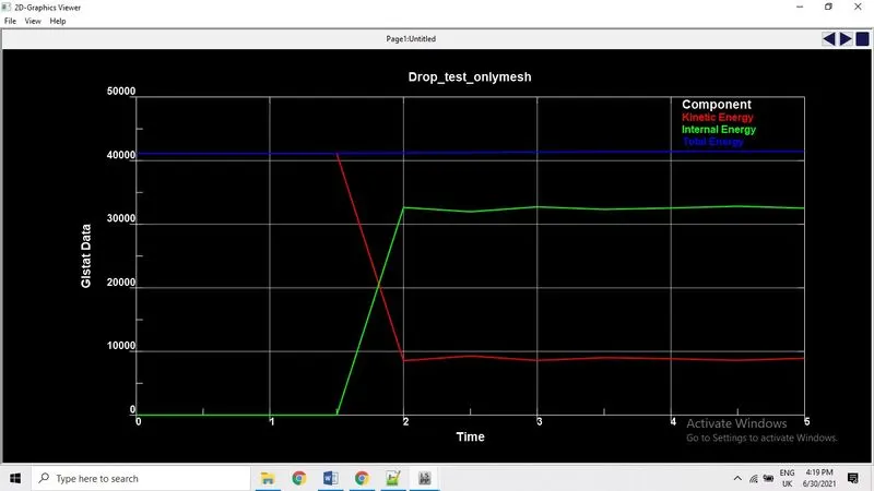
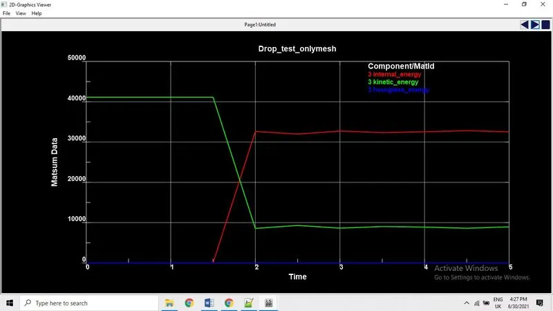
Plotting graphs: After observing the animation, now we can plot the graph using energies and contact forces using ASCII plot in the post processing tab.
First we plot the Glstat data which consist of kinetic energy, internal energy and total energy, here we can observe that kinetic energy of the phone decreases after hitting the ground and it gains the internal energy. Green and red line shows that internal energy, kinetic energy whereas blue is the total energy or hourglass energy there is no change which means these values are less compare to internal and kinetic energy. Hourglass energy should not exceed more than 15%.
Conclusion
Prepared keyword file using model file with the input data like Materials, part ID, sections, etc.
Running the simulation using Ls-run which is prepared in the Ls pre-post with normal termination.
Plotting the energies and contact forces to understand the kinetic, internal and total energies and also animation contours shows the effective stress and effective strain.