Drop test Challenge | LS-DYNA
AIM: To perform a simple cellphone drop test in LS-Dyna by creating a complete simulation file of the model given below.
MODEL SETUP:
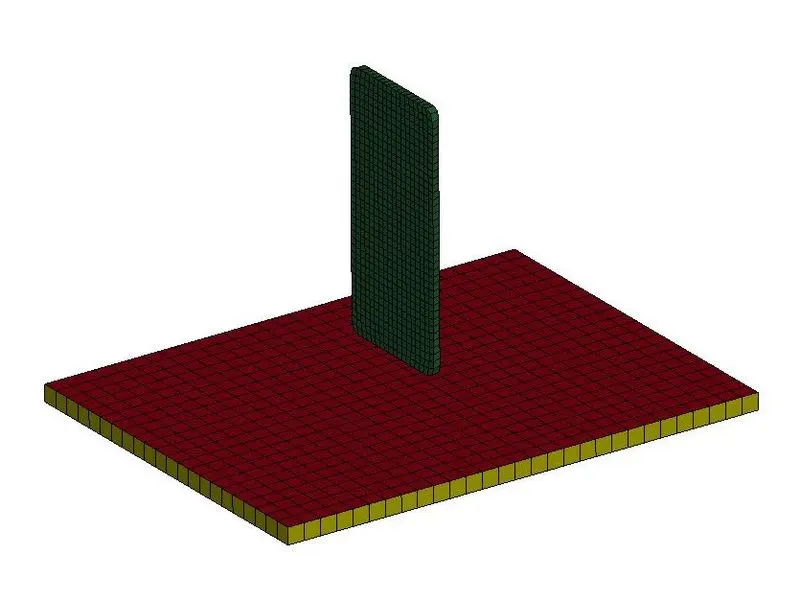
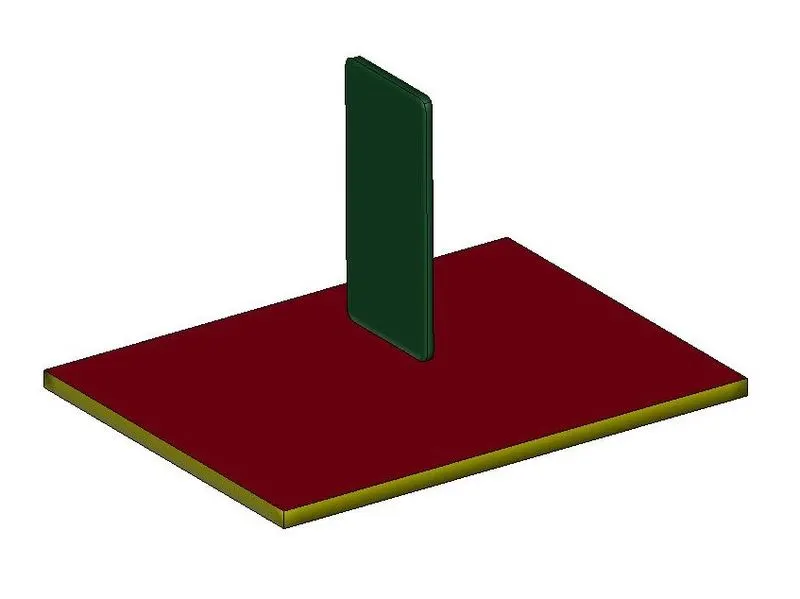
In LS-Dyna, we will first open the keyword file of the model which is named as Drop_Test_onlymesh. After importing the keyword file, we will see the model as shown above. The part in green is the cellphone and the yellow and red part is the plate mimicking ground. The red part is a shell element part and the yellow part is solid element part. To simulate a cellphone drop test scenario, we need the ground elements to be only solid elements as having both shell and solid elements can increase computational time. We can also use only the shell elements to reduce the computational time but here we will delete the shell elements and use solid elements for our simulation.
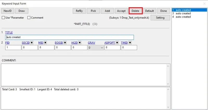
To delete the shell elements, we will go to Keyword Manager where we will select part 1 which consists of shell elements and click on delete command to delete the part.
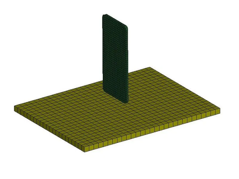
After deleting the part, the model will look as shown below.
Initial Velocity –
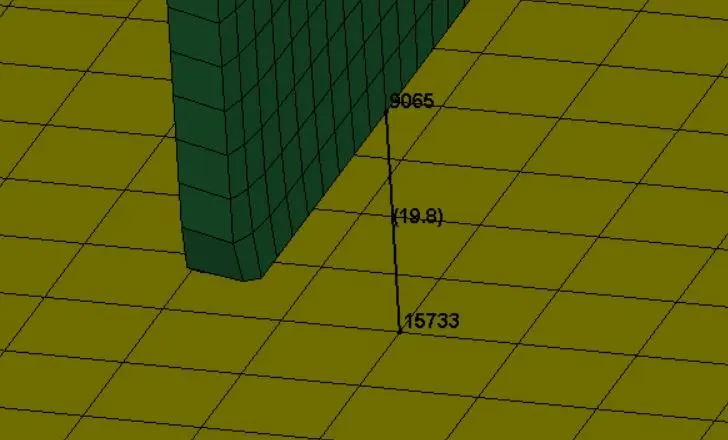
To simulate the model, we need to apply initial velocity to the cellphone in order to provide translational motion to it. The phone is under free fall condition, so we will calculate the value of initial velocity using the kinematic equations for free fall. Before this, we will measure the height between cellphone and the ground using Measure command under Element Tools. The distance between the phone and the ground is 19.8 mm as shown below.
For free fall condition, the acceleration is the due to the gravity acting on the object. Based on the kinematic equations, we have,
s = ½.gt2 and v = gt;
Where t is time, s is distance which is 19.8 mm or 0.0198 m, v is velocity and g is acceleration due to gravity which is 9.81 m/s2. Thus,
0.0198 = ½ x 9.8 x t2
t = 0.06356, substitute this value for velocity.
v = 9.81 x 0.06356 = 0.6232 m/s or 0.6232 mm/ms.
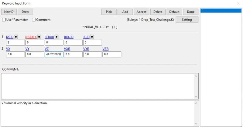
As the length is taken in mm, we will consider kg-mm-ms unit system for this model. Thus in Keyword Manager, we will create an INITIAL VELOCITY card and give the value of velocity in negative z-direction to the phone as the phone must move towards the plate or ground.
Solid Section –
As we have only solid element for simulation, we will create SOLID SECTION keyword in Keyword Manager.
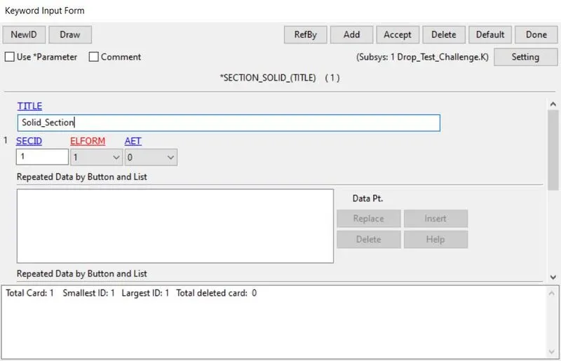
Here the Element Formulation value ELFORM is by default 1 which constant stress for solid element. After creating solid section, we will assign it to both the parts in Part Keyword.
Material –
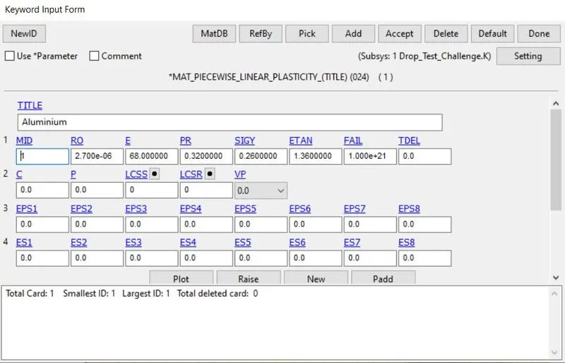
Since the phone is going to fall on the ground, the ground must be specified as rigid material so that it won’t go through any deformations. For the cellphone, we will define the material as aluminium and specify material properties to it. As aluminium is elastic-plastic material, we will use MAT_024-PIECEWISE_LINEAR_PLASTICITY material card and for rigid ground, we will use MAT_020-RIGID material card as shown below.
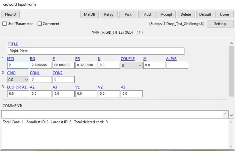
Now we will assign these material cards to the respective parts present in the model in Part Keyword. Thus the material is assigned to the respective parts.
Contact –
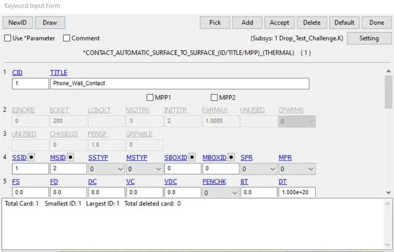
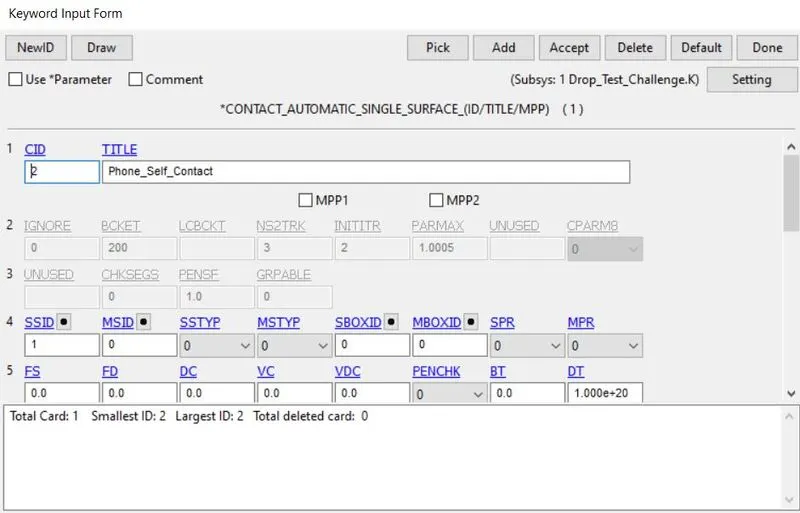
We will have to define contact between phone and the ground and self-contact for phone as the phone elements may have a contact between themselves after the deformation. So we will define AUTOMATIC_SURFACE_TO_SURFACE contact between the phone and ground elements with phone elements being slave and ground elements being the master. For phone elements, we will define AUTOMATIC_SINGLE_SURFACE contact as shown below.
Control Termination –
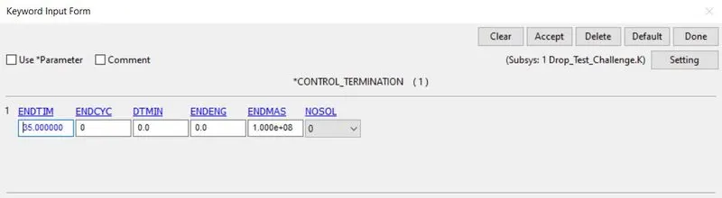
Now, we will need to define the termination time of the simulation which is necessary to run the simulation. Thus we will define the termination time as 35 ms in CONTROL SIMULATION Keyword as shown below.
Database –
After defining all the conditions required for simulation, we can generate output requests or results which we are interested in the model. So we will define BINARY_D3PLOT under DATABASE keyword and specify Time interval between outputs DT as 1 ms.
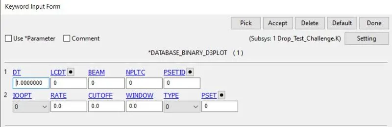
We will also ask for energy outputs using GLSTAT option, part energies of both the parts using MATSUM option and rigid wall forces using RWFORC option in ASCII Keyword. Along with this, we will create a TITLE keyword and name the model as CELL PHONE DROP TEST.
After creating all the necessary files for simulation, we will save the model as Keyword file with .K extension. To run the model, we will go to File > Run LS-DYNA. We will browse this keyword file and then run the simulation as shown below.
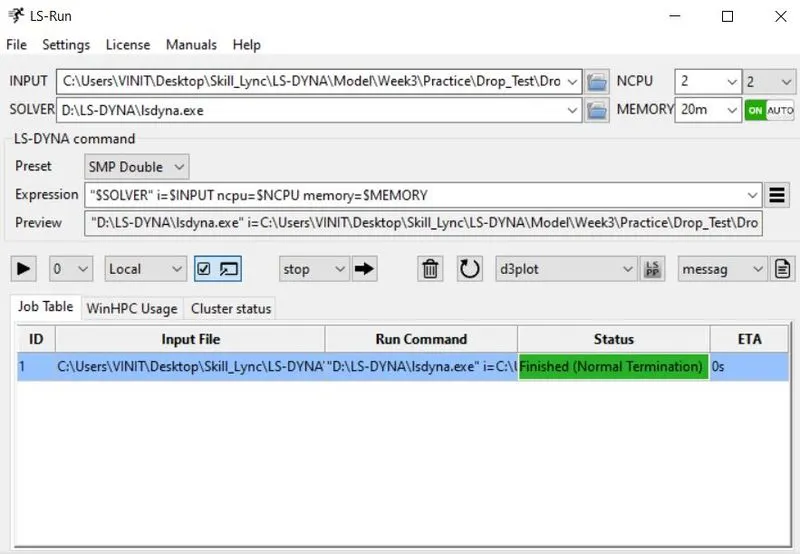
The simulation ended with Normal Termination so the model was successfully simulated as seen above.
RESULTS AND PLOTS:
To run the simulation, we will open the binary d3plot file form specified path. Then we will click on Play button on Animation Toolbar. The resulting animation is shown below.
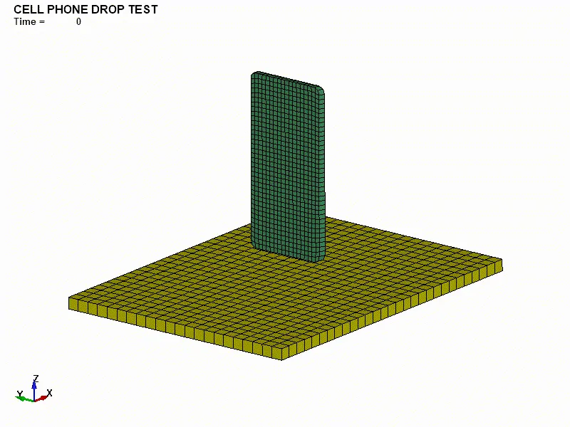
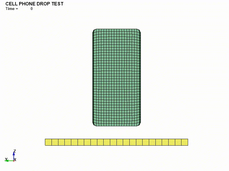
Based on the above simulation, we can see that the cell phone doesn’t deform after its impact on the ground and bounces back. This is not the real case scenario an thus we may achieve some unrealistic plots as well.
Von-Misses Stress –
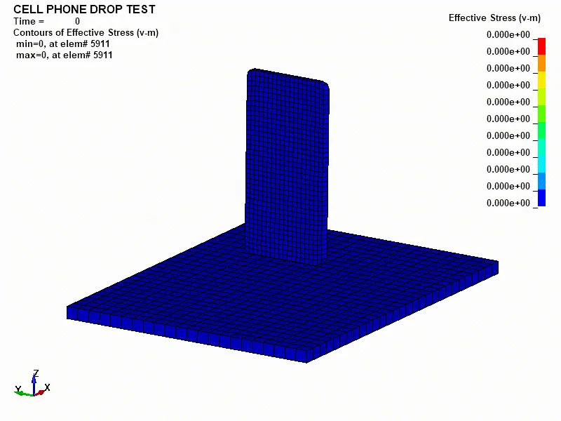
In the above animation, we can see that the phone has some initial stress before impact. This can be some error occurred during model setup. After the impact, we can see stress generation and distribution in the cellphone in which major stress is visible in center part of the phone. As the plate or ground is defined as a rigid material, we cannot see any stresses developed in the ground.
PLOTS:
Energy Plot –
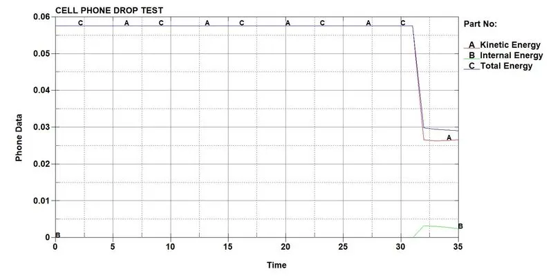
The above plot indicates the internal energy, kinetic energy and total energy of the cellphone. When the phone is under free fall, the kinetic energy is equal to the total energy as there is no internal energy in the object. After the impact, there is some internal energy and the kinetic energy is transferred to the ground. Thus we can see reduce in total energy.
Displacement vs Time –
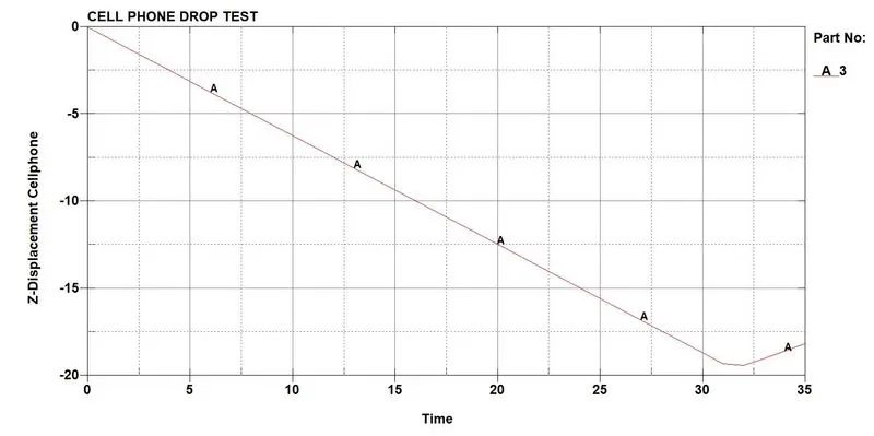
The displacement of the cellphone is 19.8 mm till the point of impact as the distance between the cellphone and ground was 19.8 mm. After the impact the displacement is increased as the cell phone rebounds after impact.
Velocity vs Time –
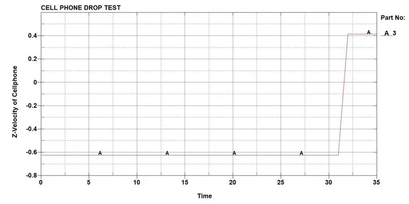
We defined initial velocity for the phone in negative z-axis. So the velocity of phone is constant at -0.6232 mm/ms till the point of contact between phone and ground. After the impact, the phone rebounds in positive z-axis at about 0.4 mm/ms.
CONCLUSION:
The drop test of a cell phone on a plate mimicking ground was performed using all the necessary keyword files for a simulation. There are no deformations observed in the model, so this condition is not realistic. By introducing more keywords and adding complexity to the model, we can simulate the realistic condition in LS-DYNA. By providing different material, we can also achieve accurate results.