Week 3 Challenge : CFD meshing on Turbocharger
Aim: - To perform surface mesh with the given target lengths as per PIDs on a Turbocharger model.
- Blade stage-1 = 1 mm
- Blade stage-2 = 1 mm
- Impeller = 2 mm
- Shaft rotor = 1 mm
- Turbo casing = 5 mm
- Compressor casing = 5 mm
- Inlet casing cover = 5 mm
Procedure: -
- Initially we download the model and import it into the ANSA software by opening the (.ansa) file. This model has some topological errors which we have to solve.
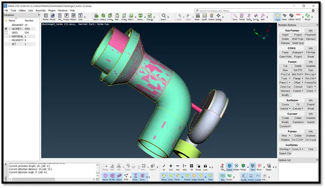
2. After deleting the unnecessary surfaces and completing the model by adding some new surfaces, we get a clean model without any topological errors.
3. Now for the ease of working, we can change the names of various PID (already created) for each part separately. This can be done by using ‘Property’ tab at top area.
4. After thus step we can proceed to mesh our model. Before performing mesh, we have to check for any geometric errors in the model by using 'Check, tab.
5. We first set the mesh length using Length option for both Perimeter and Macros. Then we use Mesh tab and set the target length, maximum and minimum mesh length respectively. Also, the mesh element is selected as Tria.
6. Next, we check the mesh quality from Quality tab and set maximum and minimum mesh length.
7. Finally, we choose any mesh type (Spot mesh in this case) and apply it to the complete model by box selection.
Compressor Body Mesh (Mesh Length = 5mm): -
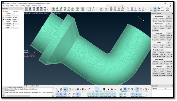
Turbo Body Mesh (Mesh Length = 5mm): -
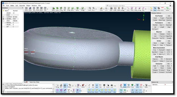
Impeller Mesh (Mesh Length = 2mm): -
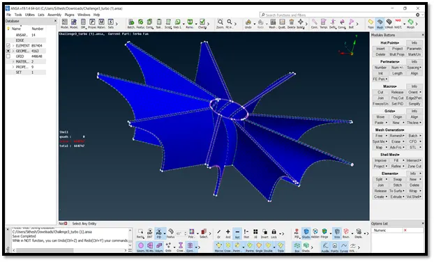
Rotor Shaft & Blade Mesh (Mesh Length = 1mm): -
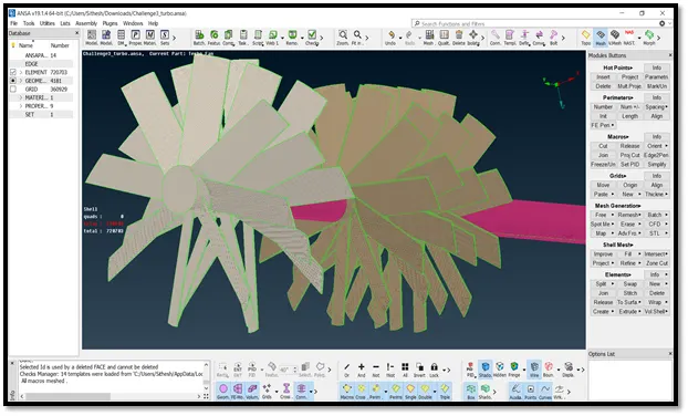
8. Once we mesh the complete model, we can move onto volumetric meshing. The first step is to define the volumes. The system will auto-detect the volumes and display it for us to choose.
9. Now we select the required volumes (the ones through which the media will flow) and delete the remaining.
10. Select every single volume separately and re-mesh it keeping the element type as Tetra CFD.
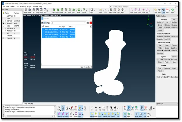
11. By using the Not option we can view the cross-sectional view of each part.
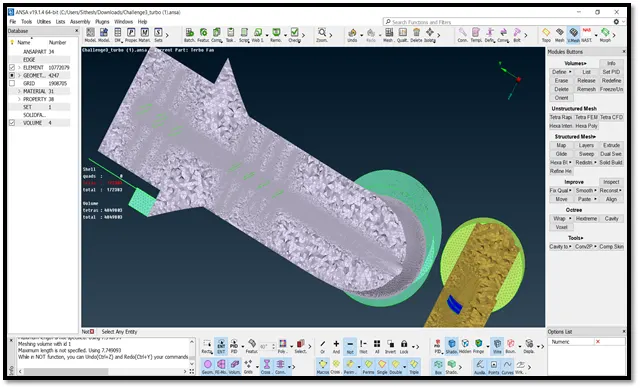
12. It is clearly visible from the figure that the region covered blades and rotor shaft has relatively small tetra elements. This is because it is a void space.
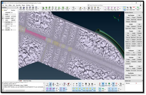
Conclusion: -
Thus, we have successfully performed surface mesh and volumetric mesh on a turbocharger model and obtained the results.