Week 3 Challenge : CFD meshing on Turbocharger
AIM
For the given model, check for the geometrical errors to make appropriate volumes. Create and assign PIDs. Perform surface mesh with the given target length per PID.
- BLADE STAGE - 1 = 1mm
- BLADE STAGE - 2 = 1mm
- IMPELLER = 2mm
- SHAFT ROTOR = 1mm
- TURBO CASING = 5mm
- COMPRESSOR CASING = 5mm
- INLET CASING COVER = 5mm
Perform Volumetric mesh for the required volumes and write a detailed report on the surface meshing and volumetric meshing.
SURFACE MESHING V/S VOLUMETRIC MESHING
Surface meshes are used in manufacturing or rendering applications and CAE simulation. Volume meshes, also known as solid meshes, use three-dimensional elements - typically tetrahedrons, hexahedrons, and polyhedrons - to define both the interior and exterior surfaces.
PROCEDURE
Topology Clean Up
The given turbocharger body has several single and double coons. So first delete the pink-coloured PID on PID mode. Then remove the unwanted surfaces using the intersection command. Delete the unwanted overlapping faces to avoid unwanted triple coons. Solve the open single coon by creating hot points for face creation.
Use the transform command under curves to use curves and hot points for face creation. For removing intersected faces on the shaft rotor use fine command under auxiliaries by selecting the surface and then selecting the shaft and middle click to separate the surface to delete it.
Use project command under coons for solving intersection errors on the surfaces of the turbo parts.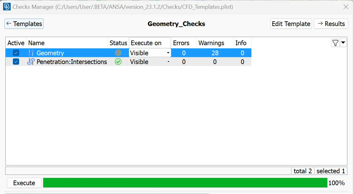
PID Creation
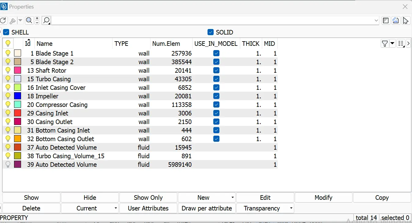
The PIDs created are:
- BLADE STAGE 1
- BLADE STAGE 2
- IMPELLER
- SHAFT ROTOR
- TURBO CASING
- COMPRESSOR CASING
- INLET CASING COVER
Surface Meshing
For each PID, the given target length should be assigned to the macros and perimeter of length command in the perimeters. The same is true for the mesh parameters, and quality criteria with
max length 7 and min length 3 for COMPRESSOR CASING, INLET CASING COVER, and TURBO CASING.
max length 3 and min length 1 for IMPELLER.
max length 2 and min length 0.5 for BLADE STAGE 1, BLADE STAGE 2, and SHAFT ROTOR.
for unmeshed surfaces use the free command under mesh generation.
Volumetric Meshing
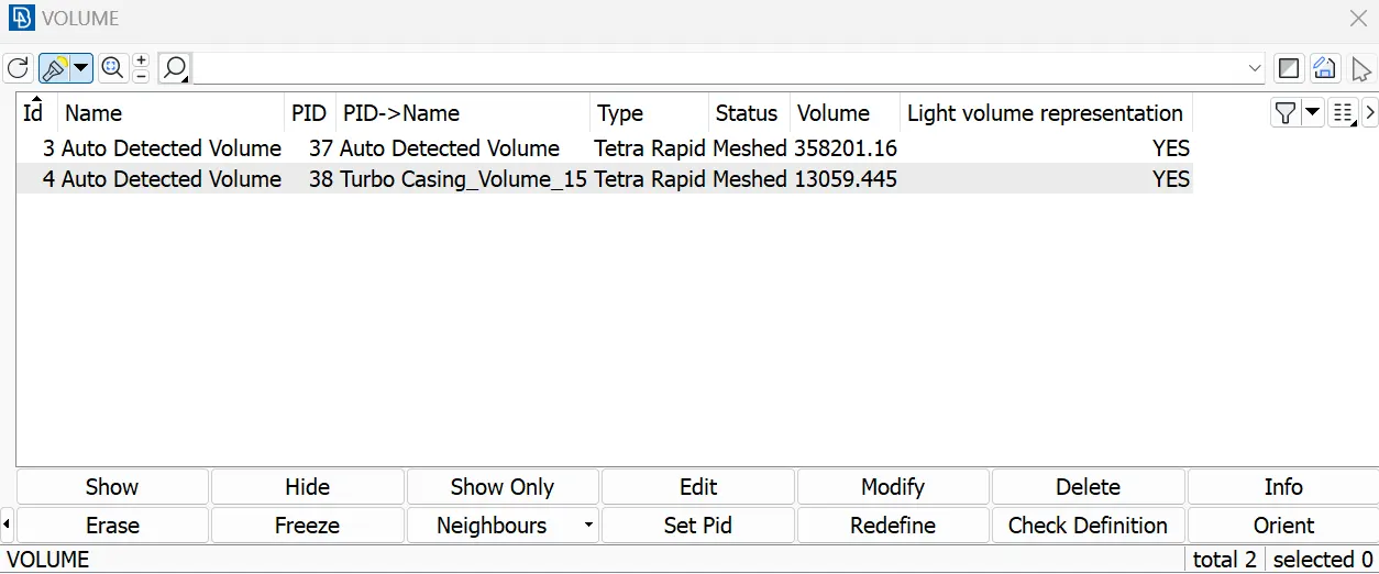
Define the body as wholedb. Open the list command under the volume mesh and several PIDs under it. So delete the unwanted PIDs which doesn't match the volume mesh. Keep the surfaces that imply the mesh and give the mesh command on the left click.
LEARNING OUTCOMES
Learned the procedure on how to mesh a water-tight body using ANSA
RESULT
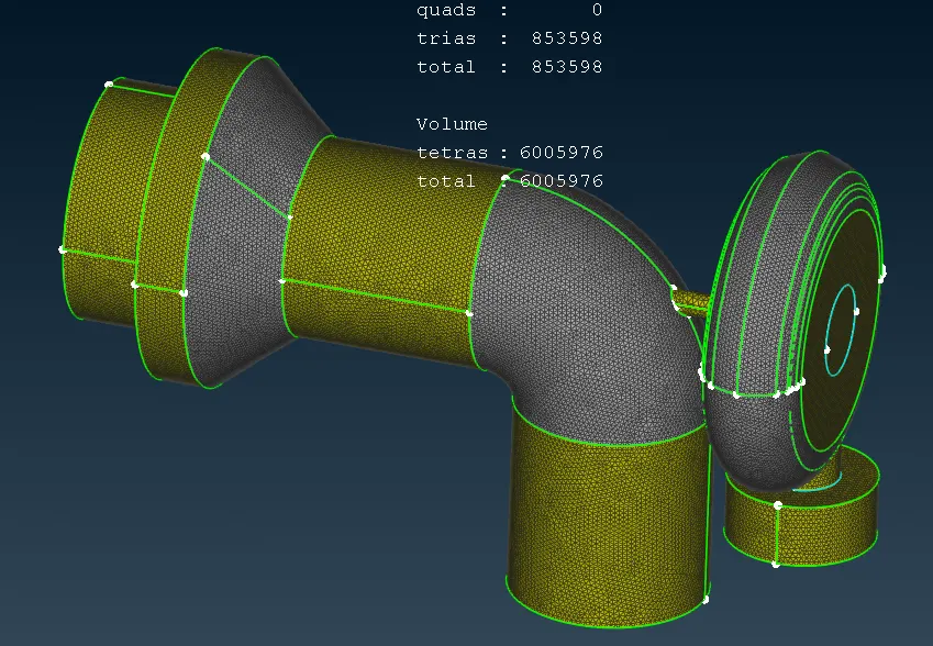
The required parameters were given in order to obtain the respective volumetric mesh and surface meshing.
The link for the turbo charger file is below:
https://drive.google.com/file/d/1NQXTapiLxdzy7PZtESWH_MrH2APCYLOU/view?usp=drive_link