Week 3 Challenge : CFD meshing on Turbocharger
Aim:
For the given model, check for the geometrical errors to make appropriate volumes. Create and assign PIDs as shown in the video. Perform surface mesh with the given target lengths as per PIDs
Objective :
For the given model, check for the geometrical errors to make appropriate volumes. Create and assign PIDs as shown in the video. Perform surface mesh with the given target lengths as per PIDs.
- Blade stage-1 = 1 mm
- Blade stage-2 = 1 mm
- Impeller = 2 mm
- Shaft rotor = 1 mm
- Turbo casing = 5 mm
- Compressor casing = 5 mm
- Inlet casing cover = 5 mm
Perform Volumetric mesh for the required volumes as shown in the videos.
Write a detailed report on your surface meshing & Volume meshing process.
Theory:
History of Turbocharger began in 1878 with the invention of mechanically powered supercharger. The birth of turbocharge is often attributed to swiss engineer Alfred Buchi(patent 1905). Turbochargers first commonly used to increase the power output of diesel engines in large passenger ships, after that they used in many aircrafts during world war 2.
Turbocharger is a one of the engine part used to boost intake air pressure of an internal combustion engine. It consist of compressor wheel and exhaust gas turbine wheel coupled together by solid shaft.
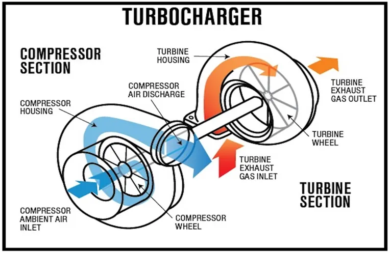
Fig.1: Turbocharger
image source: google
Turbocharger is forced induction device that is powered by flow of exhaust gases. It uses this energy to compress the intake air, forcing more power for a given displacement. The turbine extracts kinetic energy from exhaust gases to power the compressor which pressurize intake air before entering the engine. Turbo lag and boost the threshold affect power delivery and various methods can be employed to reduce turbo lag
Turbocharger differs from supercharger as they are powered by exhaust gases instead if being driven mechanically by engine. Twin charging combines both system to mitigate their weakness. Turbocharger are used in various applications including petrol and diesel engines with increasing adoption in petrol engines. Safety concerns include turbocharger failure and high exhaust temperatures which can cause fire.
Method of approach:
Procedure:
Stepwise procedure to create the volumetric mesh of turbocharger:
Geometry cleanup:
- First we load the geometry in which we first check the units and resolution of geometry and if require we do the changes.
- Next we change the orientation on geometry in which we kept one colour (yellow/grey) at outer side and another colour at inner side
For ex: grey colour at outer surface and yellow colour at inner surface
- Now we do our first geometry check where we see our geometry have errors or not (in most cases the errors are there ) or we can say its our pre cleanup geometry check. Now we run the geometry check and we fine the errors which we can see below.
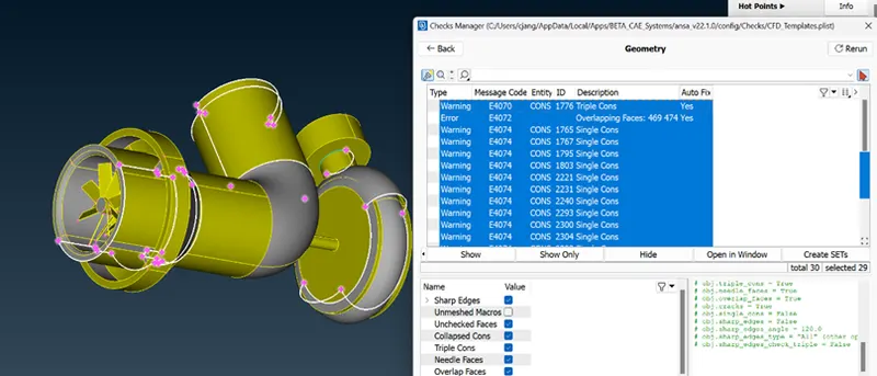
Fig 2: pre-cleanup geometry check
- Now above we see the geometry errors next we will check is there any penetration errors present or not in geometry. So we run penetration intersection check in which we got few errors which are shown below
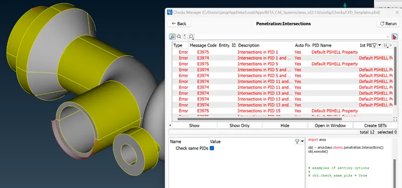
Fig 3. Intersection error present in geometry
After all these error check we can say that the geometry if full of errors and we have to do too much work on it.
- So lets begin to clear the geometry, to do that first lets switch the geometry visible in PID mode which will give us clarity and save our time to clear those errors. So first lets name all those PID or lets assign the name to those geometry components.
All the PIDs we can se below :
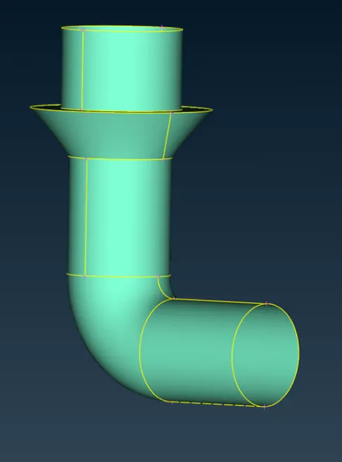
Fig 4: compressor casing
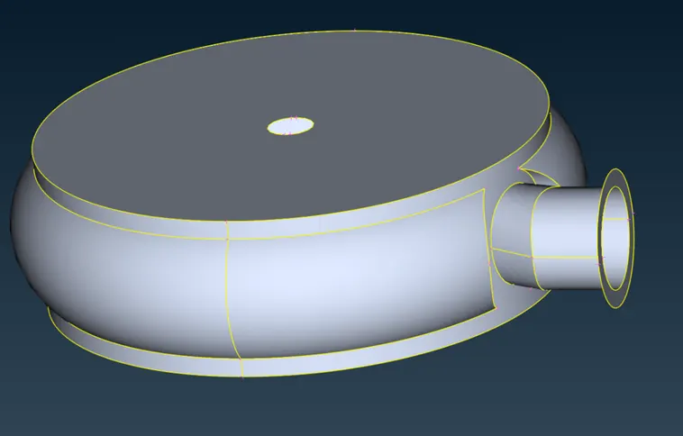
Fig 5: Turbo casing
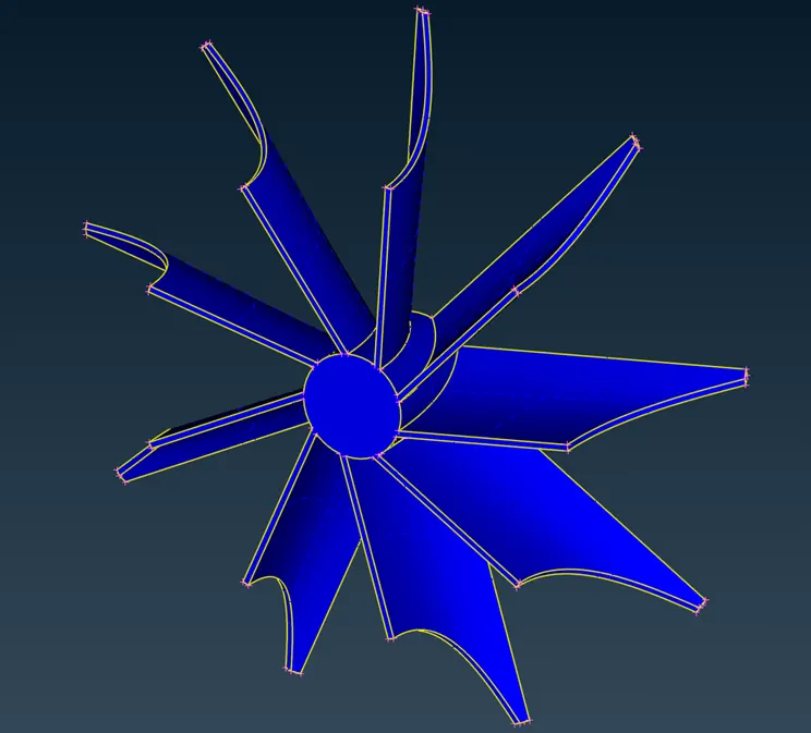
Fig 6: impeller
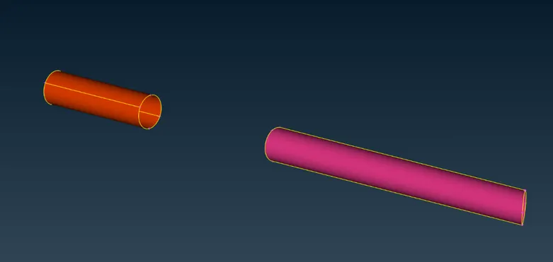
Fig 7: Shafts
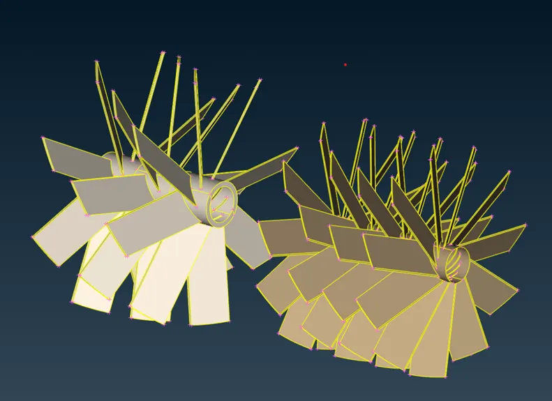
Fig 8: Blades set
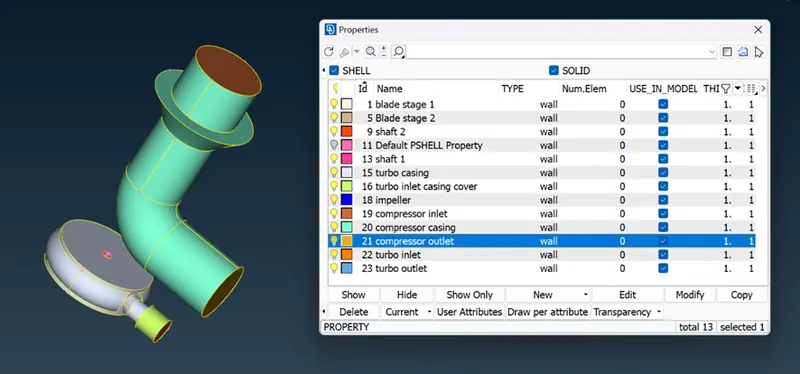
Fig 9: Complete PIDs assigned
- Now after assigning PIDs we see is there any glitches present in geometry (glitches are over lapping of two surfaces) in below image we can see there is glitch available in geometry
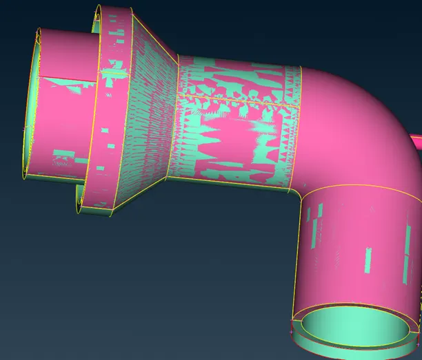
Fig 10: Glitches in geometry
Now we hide our compressor PID and delete the overlapped and extra part using universal delete option
- Now moving to clear internal errors, there are basically two type of analysis that can be done for turbochargers which are thermal analysis and internal aerodynamic flow and both analysis have different geometry requirements like if we want thermal analysis we have to focus more on thickness of geometry boundaries and all but if new want to analyse internal aerodynamic airflow we don’t need those thickness we just need internal part and its volume and that’s the thing we will do in our geometry we will delete those excessive part of geometry and only keep the internal boundary which also saves our time and required additional computational power,
- Now to delete those outer part of geometry we first separate that part from inner boundary by using release coons option this option create the gap between two surfaces and separate each other. After separating inner and outer we can select outer casing by using PID region selection tool and delete the outer selected region of turbo and compressor casing.
- After deleting and removing excessive geometry now we aims to clear the single cons and triple cons available in geometry. As we reduced our geometry our errors and warnings also decreases. Now we have to fix minimum errors like if somewhere single cons present we add the face there using new face option or we use fill hole there.
- If somewhere triple cons are visible we delete the excessive part or face present at that point. And like wise we clear our geometry.
- After cleanup when we run geometry check we get the results we can see below:
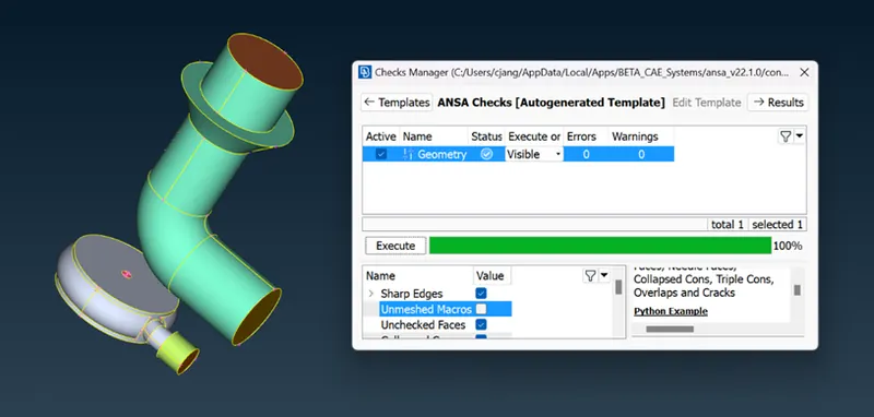
Fig 11: post cleanup geometry check
Now after cleanup when we run check we can see the 0 errors and warning are there which means we cleaned our geometry very well
Meshing:
- Now next we are going to create the mesh where first we do surface mesh and next we are going to do volumetric mesh
- For surface mesh we select the particular PID and then define mesh to those part
- To apply mesh we first define length perimeters and macros next we go to mesh and define type of mesh and target length and minimum length there and like wise we do in quality where we define minimum length and maximum length range
- After all these defining we goes to mesh generation and select the spot mesh and select geometry where we want to apply that particular defined mesh
Now we can see the meshed PID below
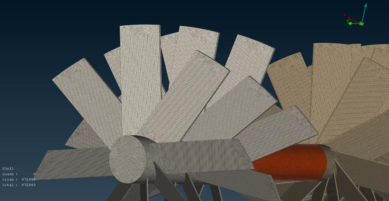
Fig 12: 1mm mesh on blades 1
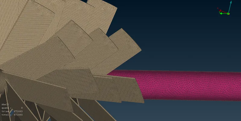
Fig 13: 1mm mesh on blades on shaft
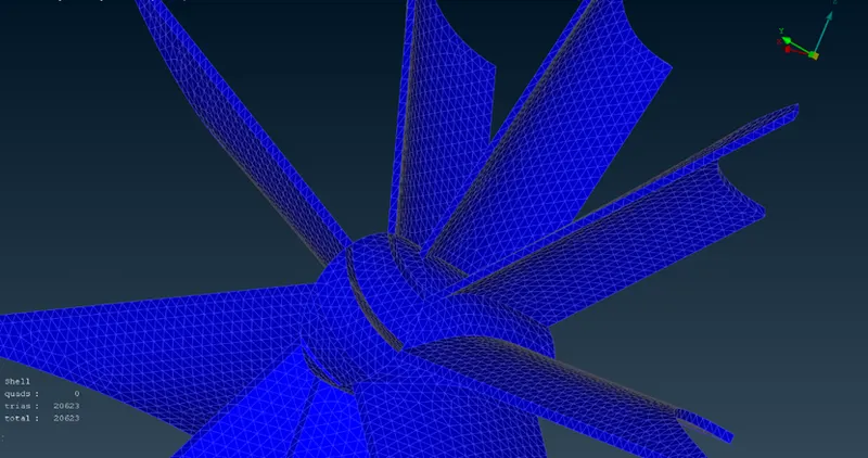
Fig 14: 2mm mesh on impeller
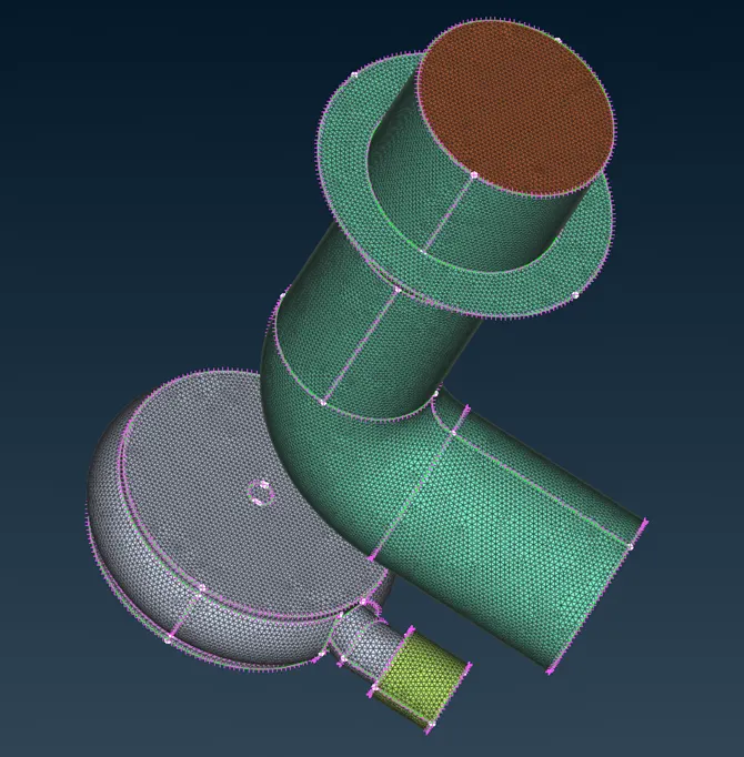
Fig 15: 5mm mesh on outer bodies
Volumetric meshing :
now as we done our near about 80% work we just now have to apply the volumetric mesh to our geometry so what we do is we go to v. mesh tab at upper right side corner where we can see 1st option of define we click on that and we get the tab that the inner part geometry is unmeshed so we right click on than and select re-mesh there to each unmeshed component and after that meshing complete we can see there we got our volumetric mesh which we can see in images
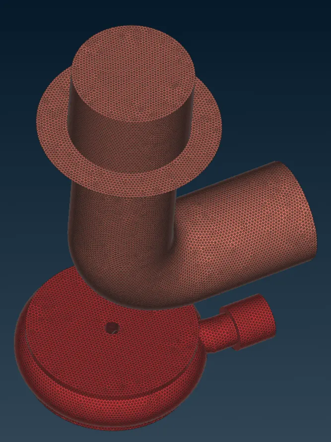
Fig 16: volumetric mesh of full geometry
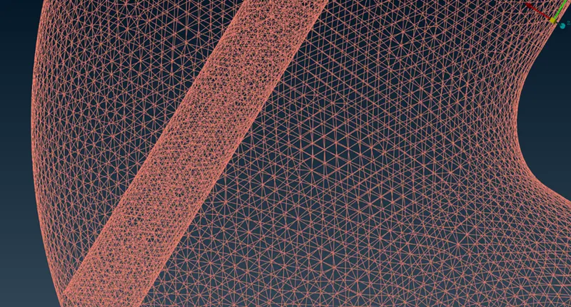
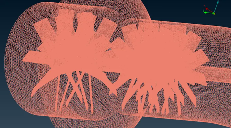
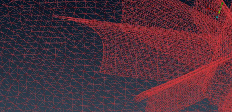
Fig 17: mesh sharing between inner parts
Learning outcomes :
We get to know here how we have to manage the geometry and do our work easy like in this case we delete the excessive parts first and then cleaned the geometry which reduces our time and errors of geometry also
Next we learned is we only have to give refined mesh at those parts where the flow is going to more focused which reduce our waste of computational power and time during meshing and simulation also
Result :
As a result of surface mesh of turbocharger we gets 768512 tria elements where as after doing volumetric mesh we got near about 6800000 tria elements.
Conclusion :
In the end we conclude that while meshing we should have idea that which area will be going under more focus and based on that we have to give refinement of mesh. Next we should know our application like I mentioned above that there are two analysis we can done on turbocharger one is thermal analysis and another is internal air flow analysis and each type have different requirements so once we cleared about application we can achieve the result in less time and with less computational power.