Week 3 Challenge : CFD meshing on Turbocharger
Aim: CFD Meshing onTurbocharger
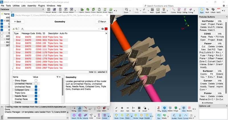
- To Check for the geometrical errors to make appropriate volumes for the given model.
- To create and assign PIDs for the various components of the geometry.
- To perform surface mesh with the given target lengths as per PIDs.
- Blade stage-1 = 1mm
- Blade stage-2 = 2mm
- Impeller =2mm
- Shaft rotor = 1mm
- Turbo casing =5mm
- Compressor casing = 5mm
- Inlet casing cover =5mm
Note:
. To Perform Volumetric mesh for the required volumes.
. To Write a detailed report on your surface meshing & volume meshing process.
Procedure:
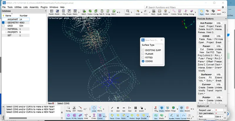
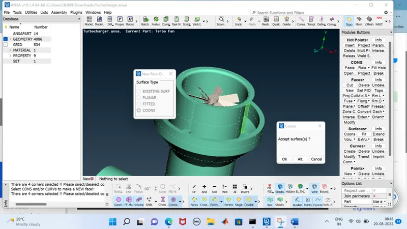
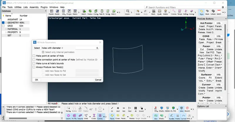
- Patch the missed surfaces:
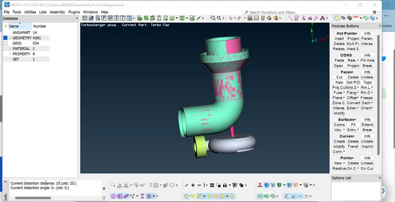
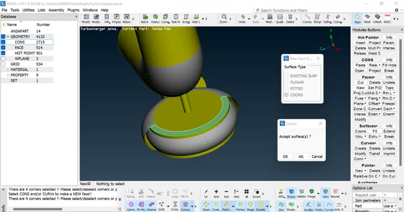
. First, we need to import the geometry model from the source folder.
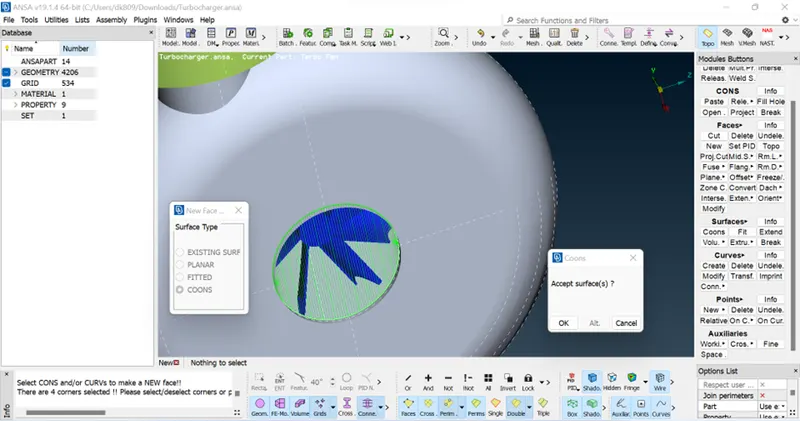
. The geometry file contains lot of irregularities, discontinuities, so we need to patch all the missing and open surfaces in the geometry.
. This can be done by the following procedure;
TOPO => Faces => New => Here we can select any method => Select the cons (This can be done by entity or PID method) => Middle click or surface click
- Removing overlapped surfaces:
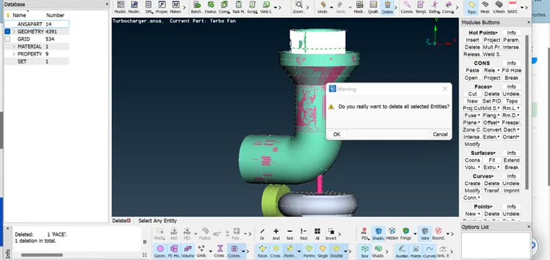
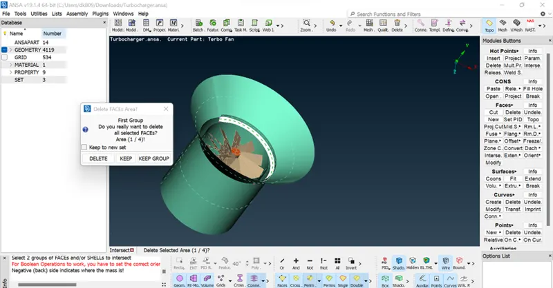
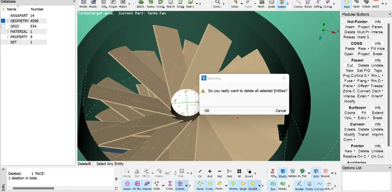
. At some areas of the geometry, we need to clear the overlapped surfaces.
. This can be done by following procedure;
TOPO => Delete => Select the surface to be deleted by using entity or PID mode.
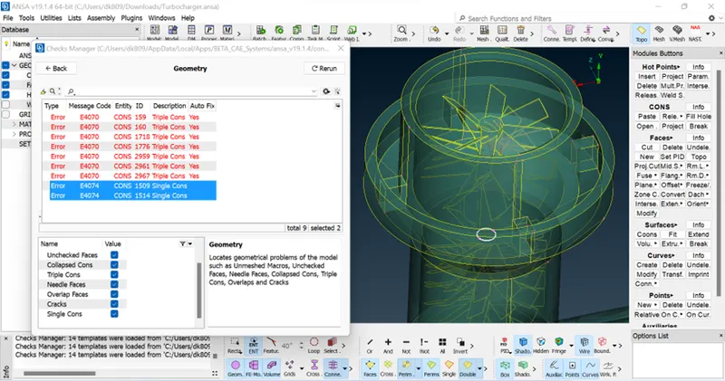
. Sometimes we need t project the cons to make the single cons into triple cons.
. This can be done by the following procedure;
TOPO => Delete => Select the surface to be deleted by using entity or PID Mode.
. Sometimes we need to project the cons to make the single cons into triple cons.
. This can be done by the following procedure;
TOPO => Cons => Project => Select the Cons => Middle Click => Select the face where the cons have to be projected => Middle click.
- PID Assigning:
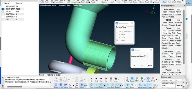
 .
.
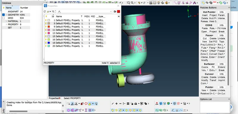
Now we need to create PID (Property ID) for all the surfaces like inlet, outlet, spring, Column, Base and Value head.
. This can be done by the following procedure;
Properties => Right click on the properties screen => New => P Shell => P Shell => Box pops-up => Name has to be given
. Similarly, we need to create as many as required.
. Now we need to assign the created PID’s to the respective Surfaces required and we need to makes sure that cross-hatches option is enabled.
. This can be done by the following procedure;
Properties => Right Click on the PID => Apply => Select the cross-hatch present in the surface of the geometry => middle click on the mouse.
. Similarly, we need to do for all the required surfaces.
Fig .
- Surface mesh process:
. Now we need to mesh the geometry.
. This can be done in two ways.
- Meshing the whole geometry in one shot. (Only with single element length can be done at a time)
- Meshing the geometry part by part individually. (Each part or component can be given different element length)
. The first method is employed in this challenge, however the second is highly beneficial when meshing distinct pieces with varying target lengths.
. Meshing can be done by following procedure;
Mesh (Right side on the screen) => Perimeters => Length => perimeters => Give the target length => ok
Mesh (Right side on the screen) => perimeters => length => macros => give the target length => ok.
Fig …………
Mesh Parameters (Top of the screen) =>Give the target length, min and max length in that dialog box.
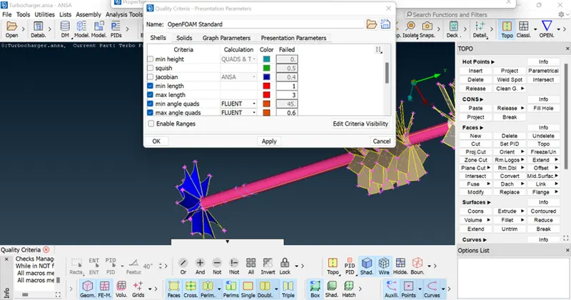
Quality Criteria (Top of the screen) => Give the target length, min and max length in that dialog box.
Fig…..
Mesh Generation (Right side on the screen) => Spot mesh => Select the geometry to be meshed.
Fig…
- Volume Mesh process:
. Now we need to move to volume mesh.
Volume => Define => Work on => Whole db
. Now we need to drop volume mesh to the geometry.
. This can be done by following procedure:
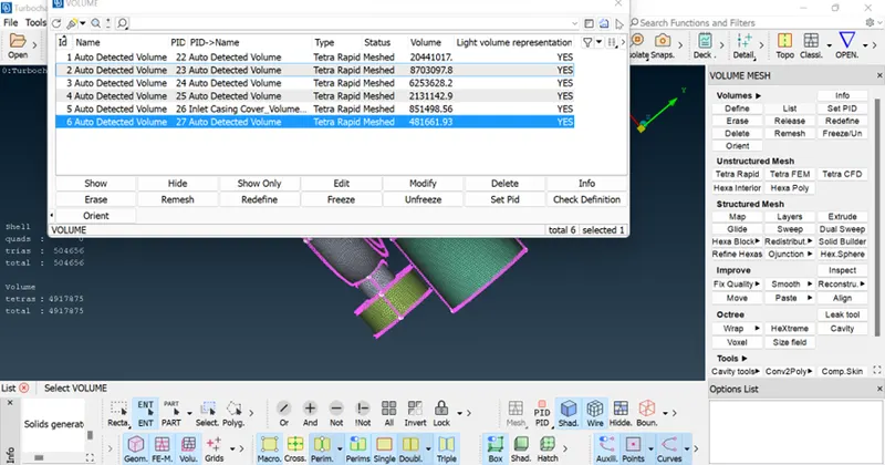
Volume => List => Here we need to select the component to do volume mesh => Right Click => Re Mesh => Fluent Method.
Fig......
Conclusion:
. The above figures are surface, volume mesh of all the components in the geometry
. The last two pictures show the cut section of the volume mesh.
. We may also deduce from the final two figure that the shaft, first and second stage blades have 1mm element sizes, while the compressor casing has a 5mm element size, resulting in a transition from 1mm to 5mm, as shows in the diagram.
Fig
Solve the Turbocharger ansa.
Properties
TOPO Clean-up: overlap bleaching