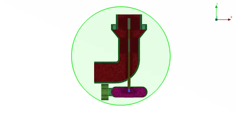
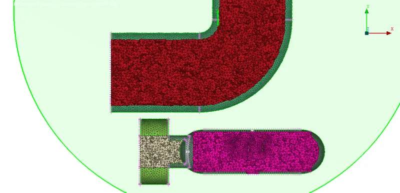
Week 3 Challenge : CFD meshing on Turbocharger
Objective: To clean up all the geometric errors of the provided model and create the surface meshing as per the challenge conditions and then create the volumetric mesh.
Process:
Cleanup all the geometrical errors using various tools as described below
Delete the unnecessary overlapping PIDs using the PID management menu
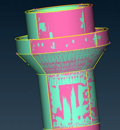
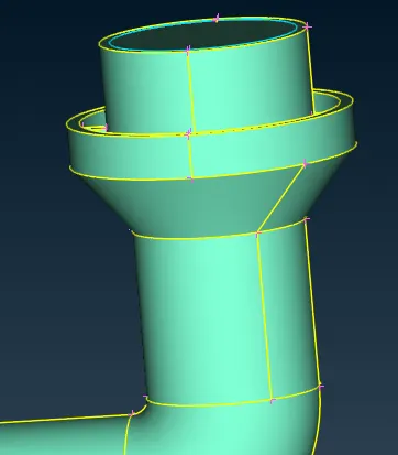
Using the delete tool of the faces menu delete the intersecting and irregular surfaces and then using the new tool rebuild those surfaces
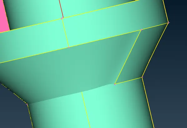
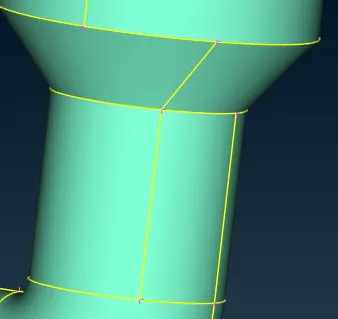
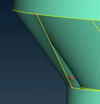
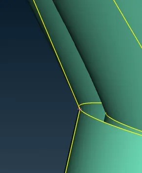
The missing surface of the compressor casing is built using the copy option of the transform tool over 3 point mirror tool used in the symmetry menu to mirror the present entity of the compressor to build the missing one. and then the fill hole option is used to fill the missing hole on the surface.
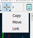
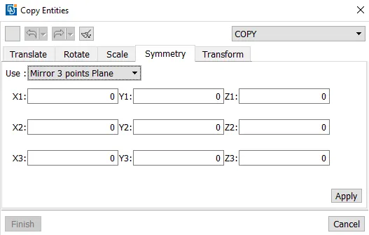
The three points could be created on the edge of the present surface using the insert hotpoints tool
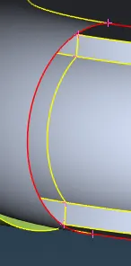
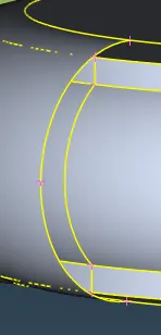
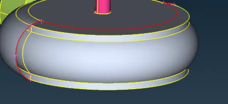
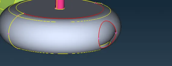
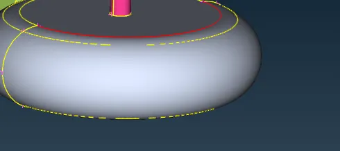
Using the new tool from the faces menu all the missing surfaces are rebuilt and also all the open inlets and outlets are closed to create the water-tight model to perform the volumetric meshing using the same new tool.
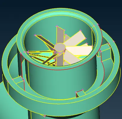
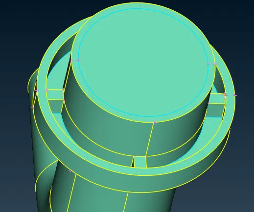
and then all the overlapping and unnecessary surfaces of the shaft and impellor are deleted and then using the project and topo tool of the cons menu all the single cons errors are fixed
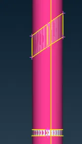
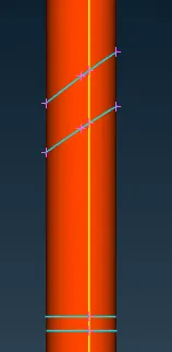
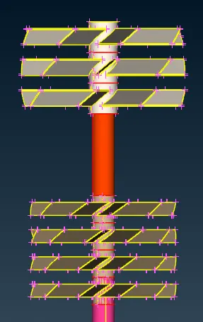
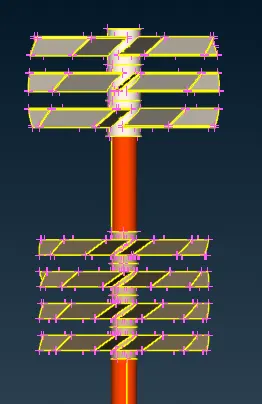
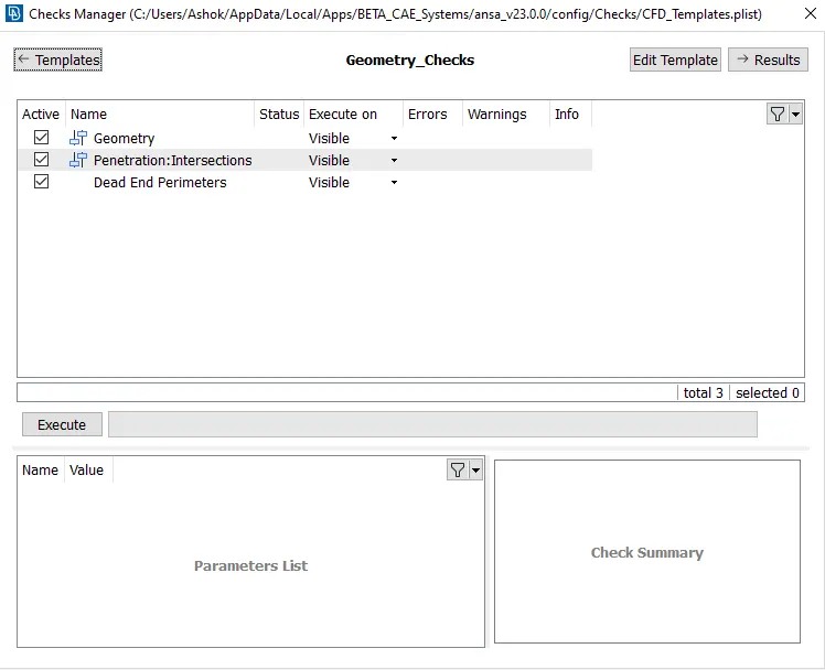
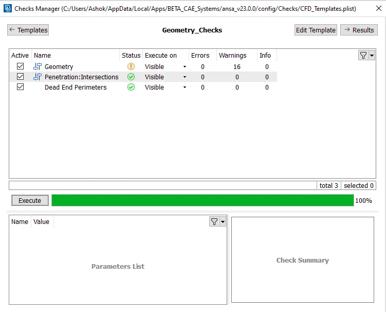
After completing the geometric clean up the geometry is verified using the check manager tool which would show all the geometrical, penetration, and intersections errors if present
After all the errors are resolved, now the PIDS are segregated and renamed according to their function in the PID manager.
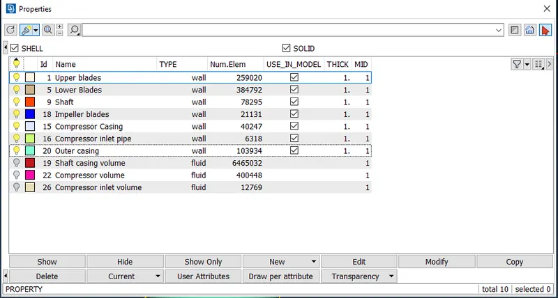
After this surface meshing of the model is performed. The surface mesh is prepared according to the challenge guidelines, which for the shaft and two upper blades the mesh size is 1mm and for the impellor blades the mesh size is 2mm and for the casings, the mesh size is 5mm.
Mesh sizes are updated in the quality and meshing parameters as per the required mesh size
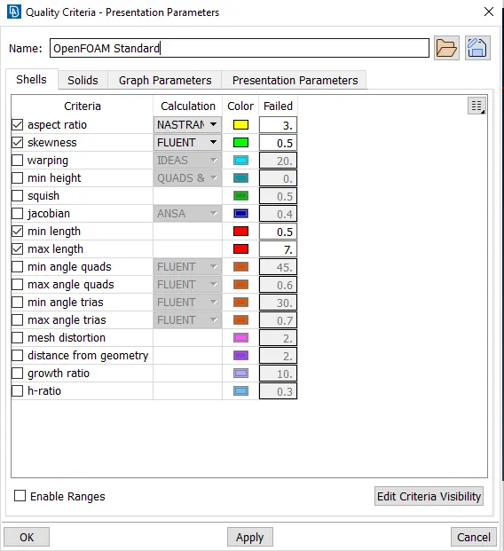
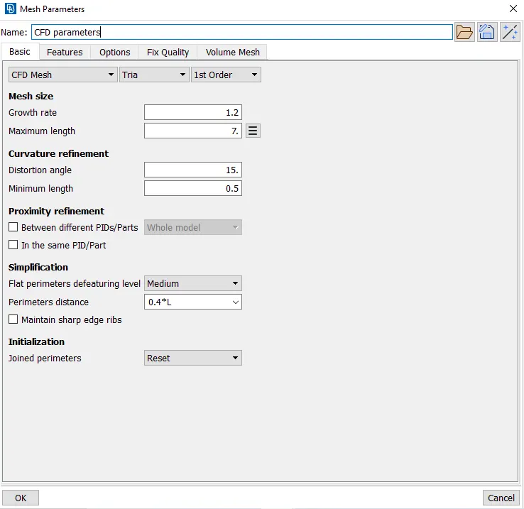
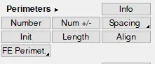
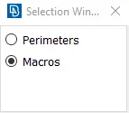
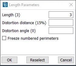
And the mesh size of the cons and faces of the model is updated using the length tool of the perimeter menu in the mesh toolbar. Here the perimeters option is for the cons mesh size and the macros option is for the faces mesh size
After the spot mesh and CFD mesh tools are used to mesh the surfaces of the model and then if some of the elements of the mesh are off to the quality parameters they are improved using the reshape and reconstruct tools.
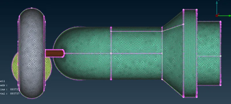
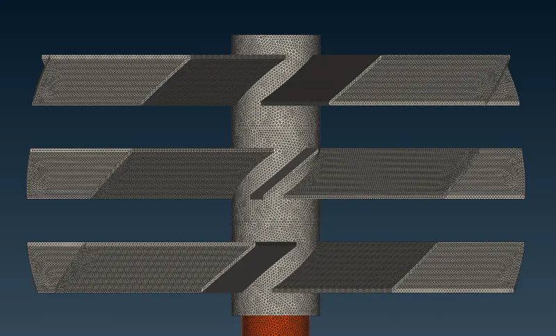
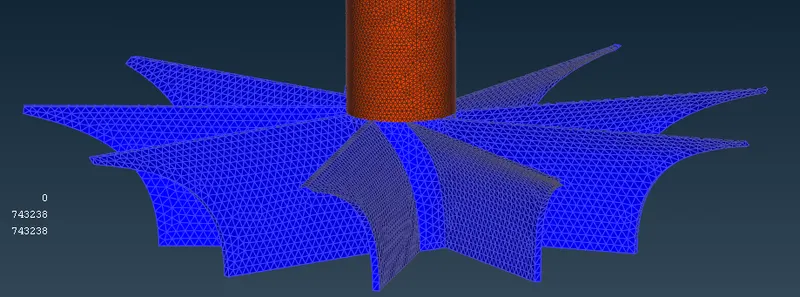
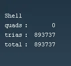
After preparing the surface mesh, the volumes of the model are defined using the Define tool in the Volume menu of the Vmesh toolbar and then all the unnecessary volumes are deleted. And the type of the volumetric mesh is defined as tetra CFD in the type section of the define menu.
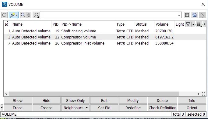
And then the mesh tool is used in the define menu to perform the volumetric meshing of the defined volumes.