Week 3 Challenge
1. Following factors are used in fixing span as per IRC standards and type of bridge are :
Planning Strategies (104.1.1) :
Integration with Road Network : The first step in the planning of a bridge project is to ascertain its location in the link of the road network and function thereof. The bridge shall fit into the road link in a seamless manner and contribute to its primary function. Most road links have both mobility and accessibility functions in varying degrees, which shall be taken into account while planning.
Interaction with other Authorities and Public: It is necessary to interact with authorities and local public who are directly or indirectly connected with the project or whose works or authority will be directly or indirectly affected.
Siting of a Bridge: A bridge should ideally be sited across the narrowest width of the river or channel where the course of the channel is straight in considerable length IRC:5-2015 12 on both up-stream and down-stream sides of the site and the banks are stable having no history of being out-flanked. A bridge should not be sited across meandering stretches of rivers unless it is established that the banks at the bridge site are the nodal points of the river (i.e. the river has a history of touching these points year after year regardless of change in its course elsewhere).
The following shall be the guiding considerations in this regard:
i) Bridges up to a length of 60 meters - The location shall be governed by suitability of alignment of road, unless there are special problems at the crossing with regard to design and maintenance of the bridge.
ii) For bridges having a length between 60 m and 300 m - Suitability of site of the bridge as well as that of the alignment of approaches shall be considered together.
iii) For bridges having a length more than 300 m - The requirement of a good site for the bridge shall have the precedence and the alignment of approaches will have to conform to the selected bridge site.
DESIGN CONSIDERATIONS :
a) General Data including Maps, Plans and Topographical Features
b) Hydraulic Data for Selected Bridge Site
c) Geological and Seismological Data for Selected Bridge Site
d) Sub-surface Data
e) Environmental Data
f) Loading and other Data
g) Traffic Data
h) Construction Materials
i) Special Design Requirements
j) Existing Services
k) Labour Accommodation
l) Other Authorities
m) Data Regarding Existing Bridges
104.3 Width of Carriageway, Footpath and Median: Width of Carriageway and Overall Width For high level bridges constructed for the use of road traffic only,
The width of carriageway shall not be less than 4.25 m for a single lane bridge
7.5 m for a two-lane bridge
and shall be increased by 3.5 m for every additional lane of traffic for a multiple lane bridge.
For a bridge on a horizontal curve, the roadway width shall be increased suitably to conform to the requirements stipulated in the relevant IRC Standards.
Width between the outermost faces of the bridge shall preferably be equal to the full formation width of the approaches.
However in case of bridges having length more than 60 m in non-urban areas, reduced width may be permitted by the authorities subject to stipulations as given in Clause 104.3.1 above.
Width of Median : The median width of the approach road shall generally be carried over the bridge. In case of major bridges, the median width may be reduced, subject to a minimum width of 1.2 m, in which case, crash barriers shall be provided in the median.
WIDTH OF footpath: is provided, its clear width shall not be less than 1.5 m. For urban and populated areas having large concentration of pedestrian traffic, the width of the footpath shall be suitably increased.
Clearance - Navigational Navigational clearances, both vertical and horizontal, shall be provided based on classification of waterway as per the requirements of Inland Waterway Authority of India (IWAI) or the concerned Port authorities. 104.4.2 Clearance – Over Roads
104.4.2.1 Vertical The minimum vertical clearance of any structure provided over the project road shall be 5.0 m for non-urban areas and 5.5 m in case of urban areas. In case of structures over local or collector streets, where only light commercial vehicles are plying and where alternative routes for heavy commercial vehicles and fire tenders are available within a short distance, the authorities may relax the clearance requirements stated above.
For a bridge constructed on a horizontal curve with super elevated road surface, the horizontal clearance shall be increased on the side of the inner kerb by an amount equal to 5 meters multiplied by the super elevation. The minimum vertical clearance shall be measured from the super elevated level of the roadway. Extra horizontal clearance required for the super elevation will be over and above the increase in width required on a curve. IRC:5-2015 16 104.4.3 Clearance - Over Railway Lines For ROBs across railway lines, horizontal and vertical clearances shall be governed by the requirements
of the  authority.
1B
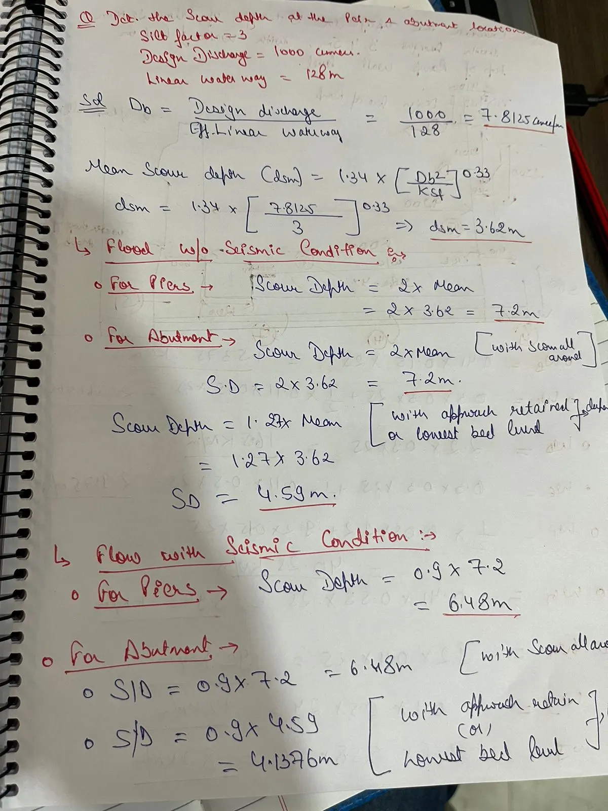
Preventing Scour: Underpinning:
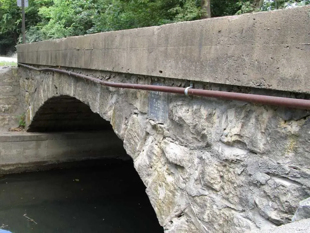
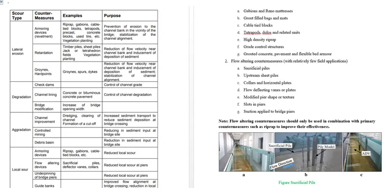
The most ideal solution when it comes to preventing a stone arch bridge from being scoured out and collapsing is underpinning. Underpinning consists of extending the foundations downward by carefully digging below the bridge, and then supporting the bridge from below with a firm, scour-resistant material.
Preventing Scour: Streambed Paving
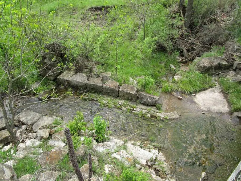
Another solution is to try to prevent scour under the bridge altogether. This can be done by paving under the bridge with concrete or some other scour-resistant material. This new solid streambed under the bridge forms a barrier between the water and the bridge’s foundations, effectively protecting the bridge from scour.
Preventing Scour: Aprons
An even simpler and relatively inexpensive solution to the scour problem is the use of concrete aprons around the piers and abutments of the bridge. In Kansas, this is a popular solution, and appears to be remarkably effective. The water simply cannot dig under the piers; it has to undermine the apron first, which takes time. The concrete apron is something of a localized streambed paving and a highly economical solution.
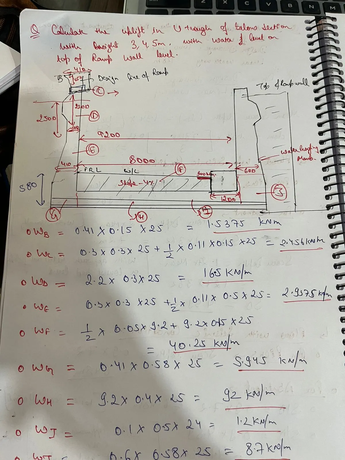
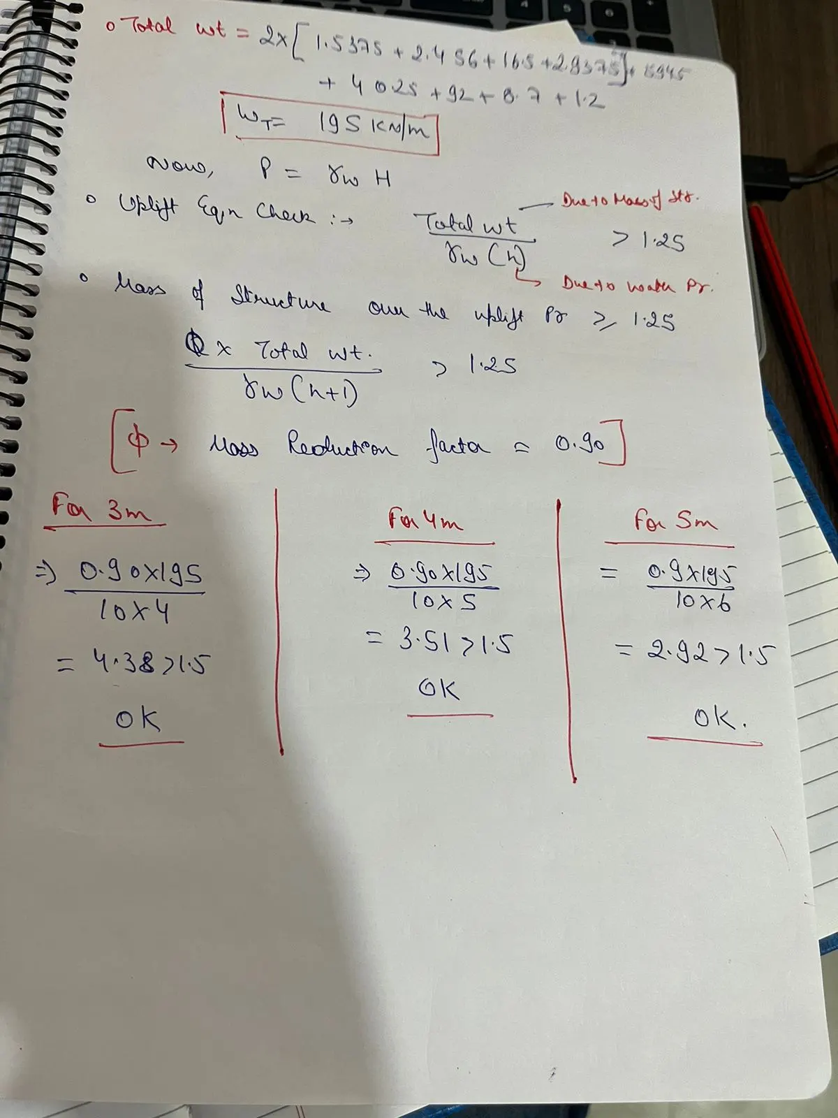
How to Check for Uplift Pressure?
The weight of the substructure should be greater than uplift pressure in order to meet the requirements of applicable codes, i.e. summation of downward load per given area should be larger than that of the vertical load per given area.

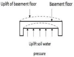
The consequences of Uplift pressure are:
Prevention methods Uplift Pressure
The preventive measures for Uplift Pressure are:
Toeing in the Foundation into the Surrounding Ground:
Extending the base slab or raft foundation beyond the excavation or cofferdam perimeter, incorporating backfill material to increase resistance against uplift pressure.
Increase Self-weight of the Structure:
Enhancing the self-weight of the building by enlarging structural members or incorporating features like rooftop gardens with substantial soil fills, especially in low-rise podiums within high-rise complexes.
Ground Anchors:
Utilizing prestressed anchors as a temporary solution to counteract uplift forces, with permanent applications limited due to concerns about long-term corrosion performance.
Piling Method:
Employing various pile types in the piling method as the most effective strategy to resist uplift pressure, choosing piles based on soil conditions and specific site necessities.