Week 3 Challenge
Volumetric Meshing of a Turbocharger
Objective
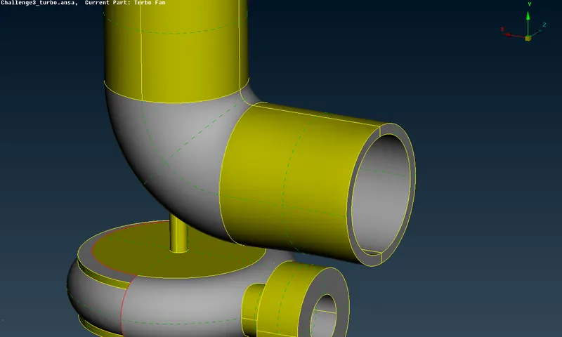
Resolve all errors in the provided geometry. Create and assign PIDs perform surface mesh with the given target lengthes as per PIDs, eventually perform volumetric mesh for required volumes.
Geometry
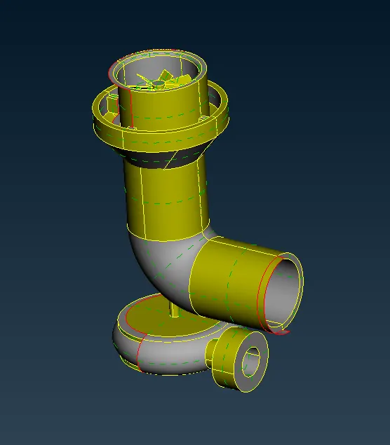
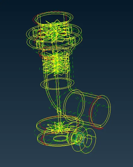
Check Geometry
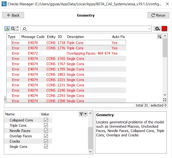
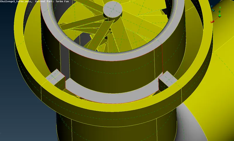
Firstly before staring surface meshing we should make sure that the geometry is perfect, without any errors, therefore we checked the geometry and found out that we have a lot of single cones and intersections which should definetely be resolved.
Before staring resolving single cone errors, we have found out that in the geometry there are some intersecting faces in pink color which should be deleted.
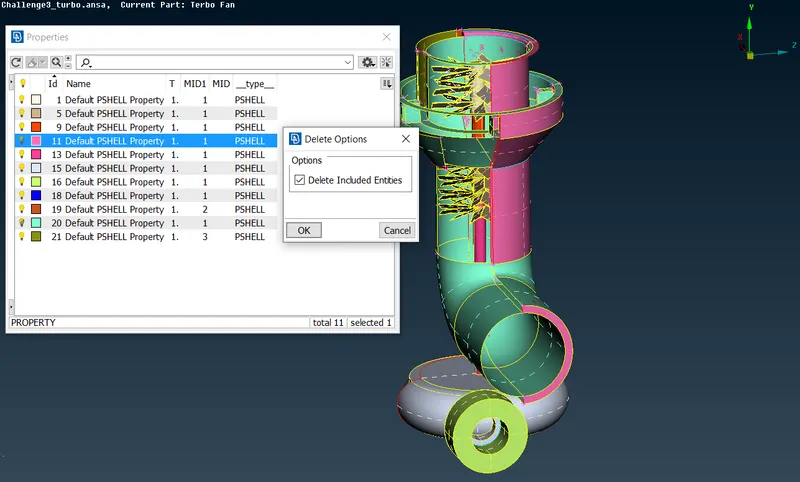
Resloving other intersection
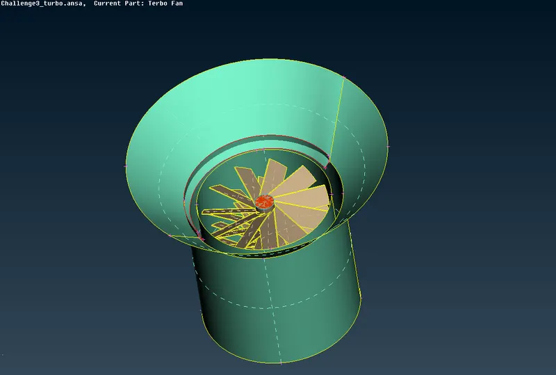
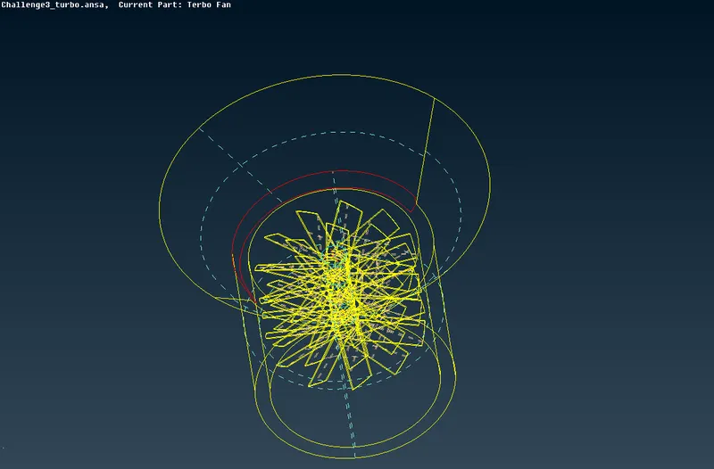
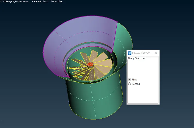
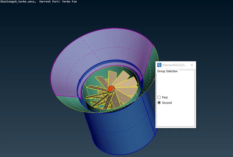
The intersection is resolved.
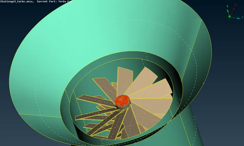
Resolving single cone errors
1.
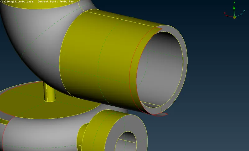
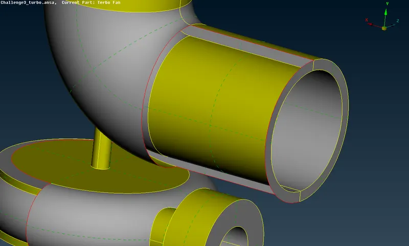
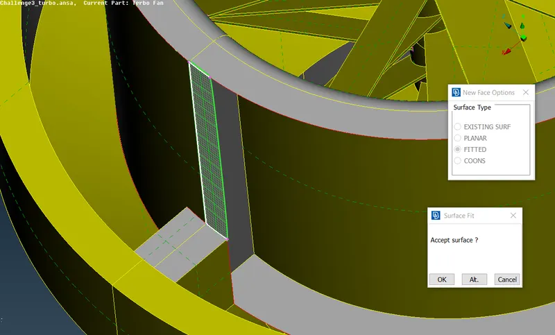
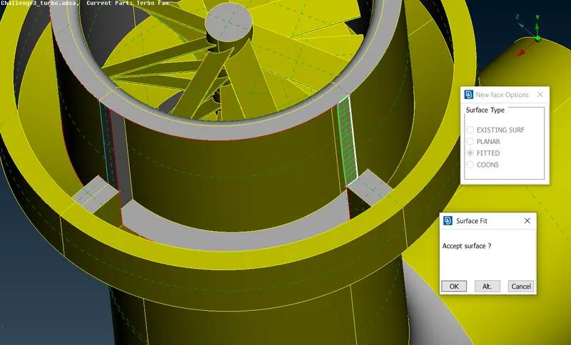
After deleting the spoiled face, let's create the new one.
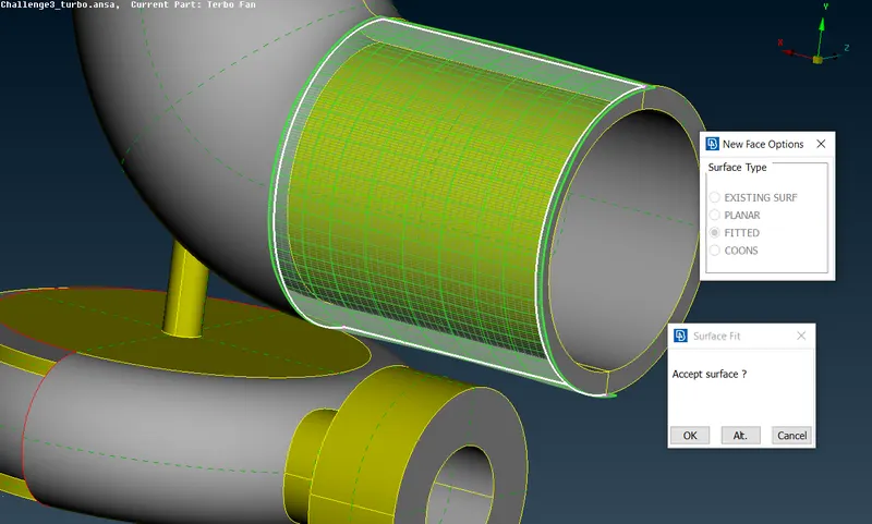
2.
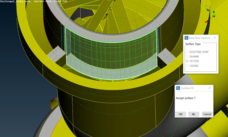
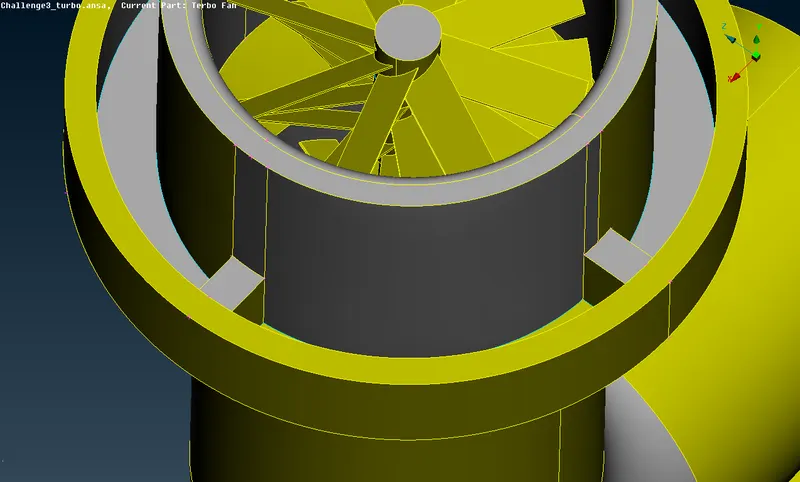
3.
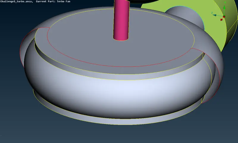
let's create hot points on the open single cone using command "parametrics"
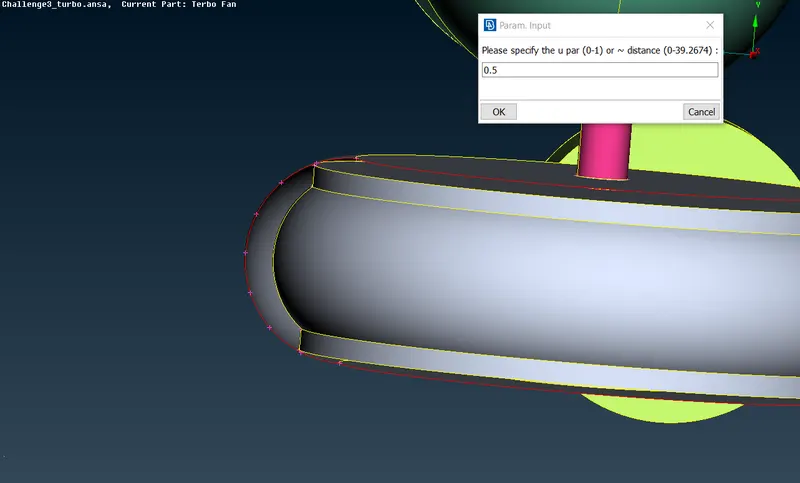
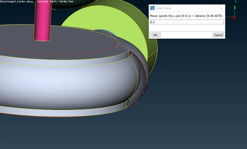
After that we should create new faces along this curves divided by hot points.
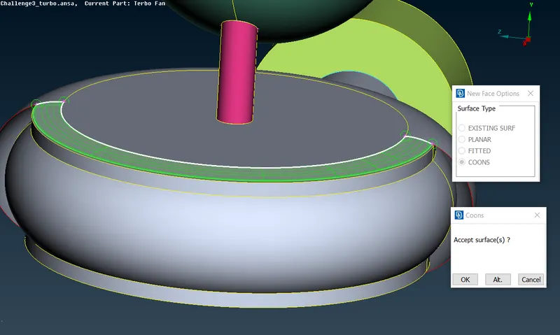
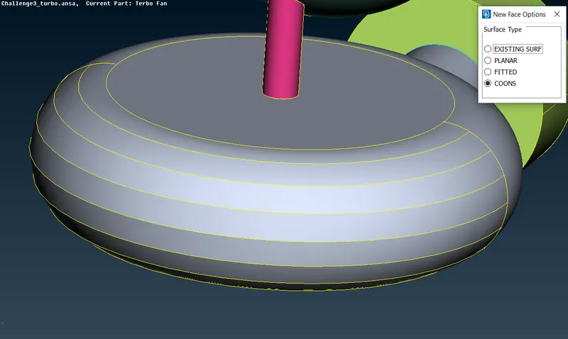
After repeating this method on the other hot points we get the result shown below.
As you see in the figure below pink and brown color faces share the same area, therefore we should cut the pink color geometry to delete the part which coincides with the brown color surface.
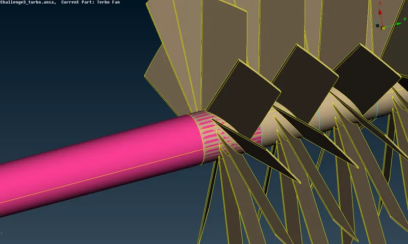
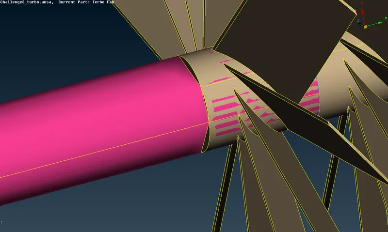
we successfully cut the surface, however it's clear that the curve is not as smooth as needed anymore. we must resolve it using the command "Fine"
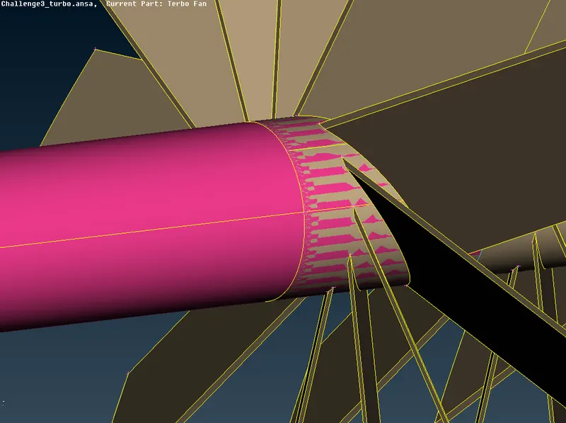
Now we should delete unecessary part of the pink PID.
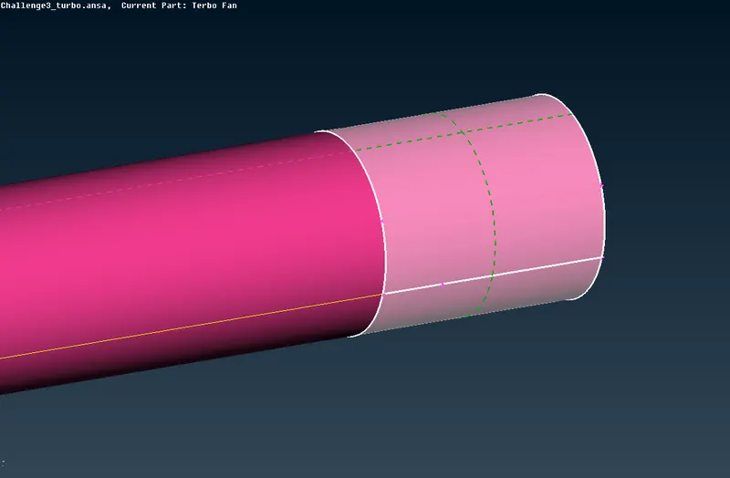
after deleting the surface shown above the error is resolved.
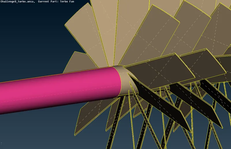
Now we should resolve all triple cone issues. (Marked in blue color)
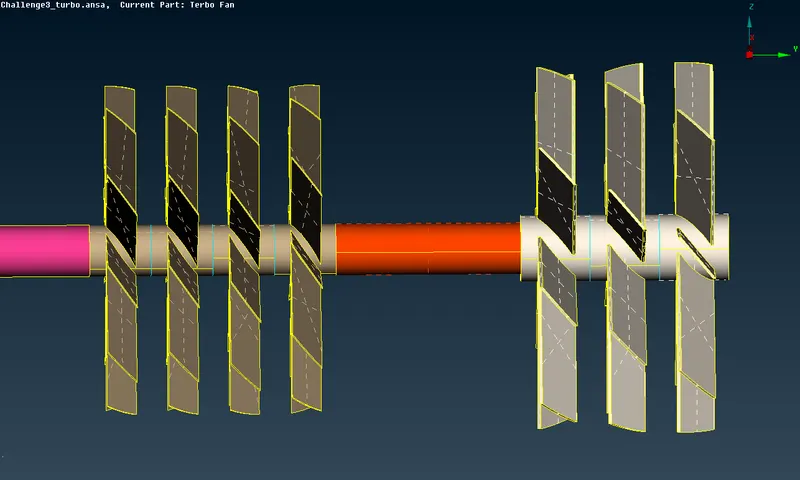
we can do that hiding blade hub faces and deleting face which which shown below.
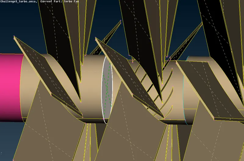
Let's do this same process for all triple cones.
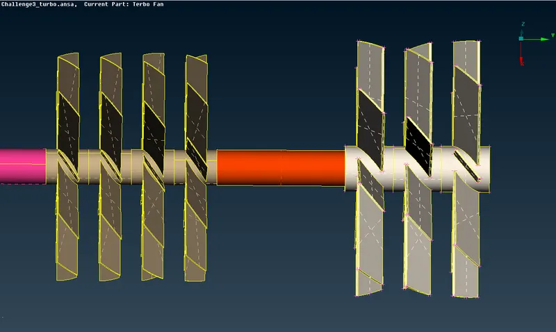
All triple cone issues in the sown area above is resolved.
After completing Geometry clean up we should recheck it.
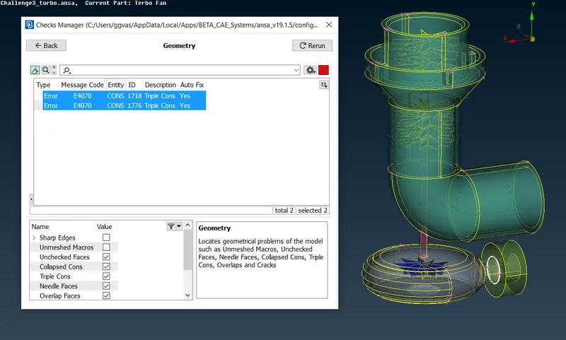
As we see 2 triple cones are still present, however in this case we can not delete any face, therefore this triple cones won't make any problems in further work.
PID
Now it's time to make named selections of each PIDs.
Compressor Casing
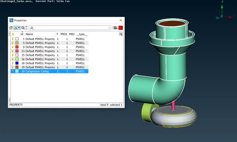
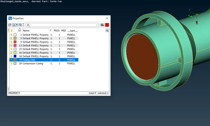
Casing Inlet
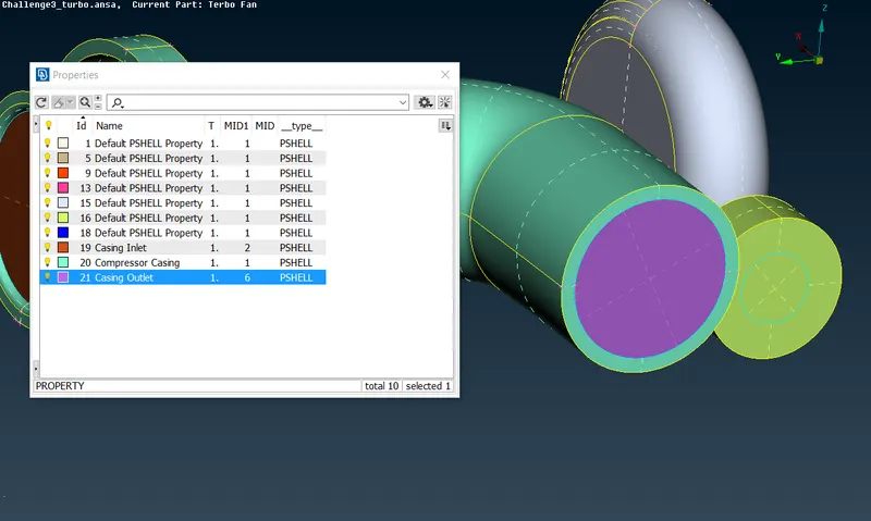
Casing Outlet
Blade Stage_1
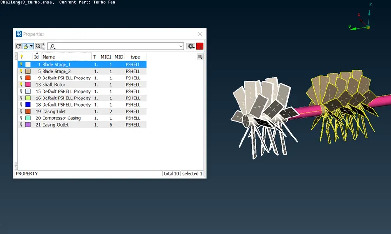
Blade Stage_2
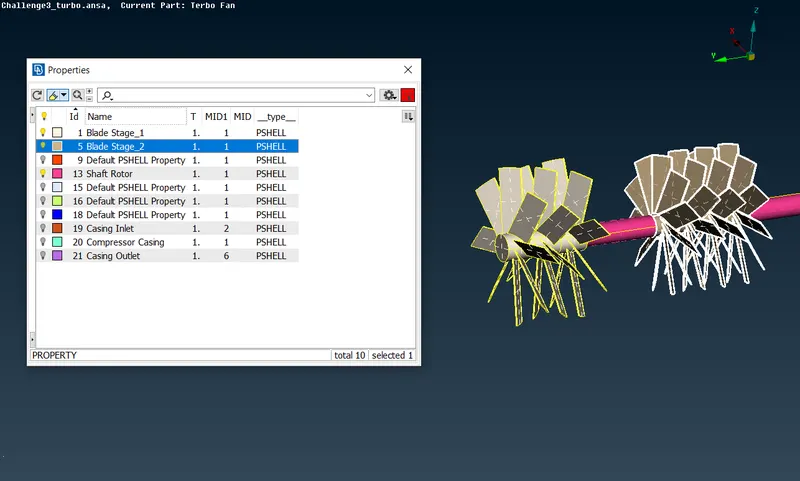
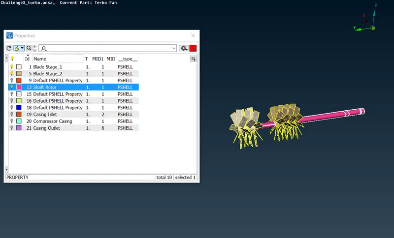
Shaft Rotor
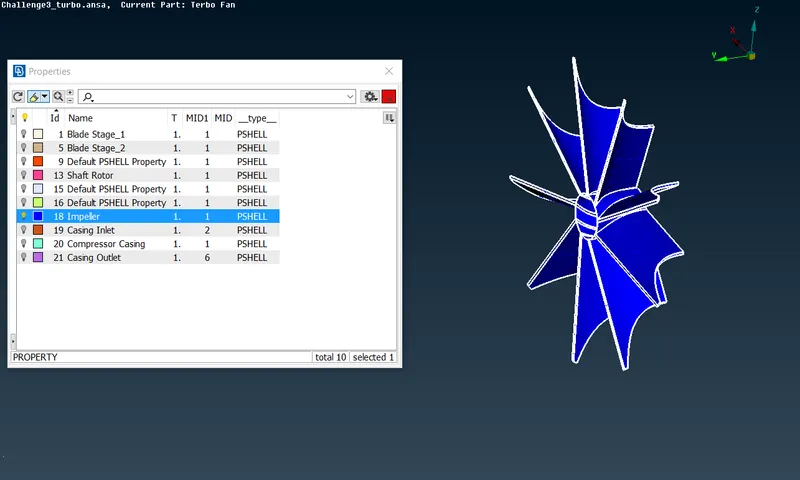
Impeller
Turbo Casing
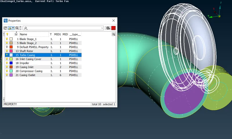
Inlet Casing Cover
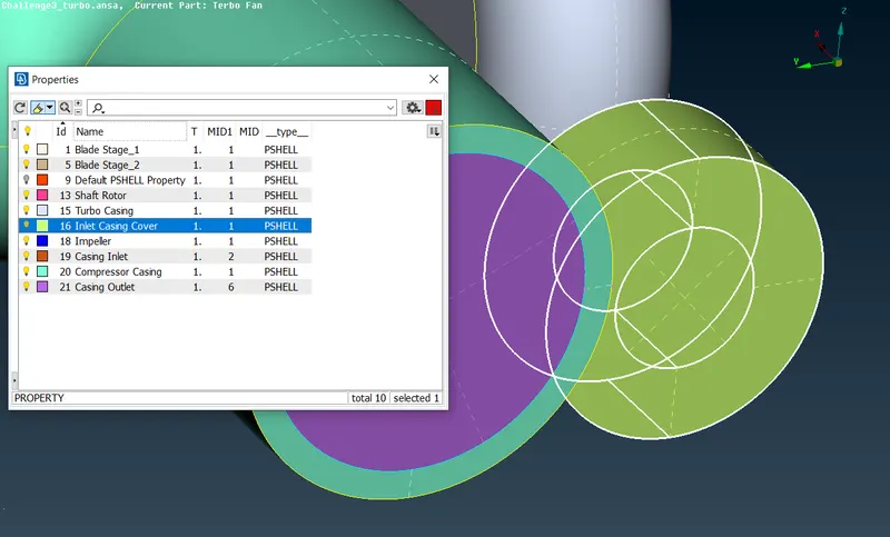
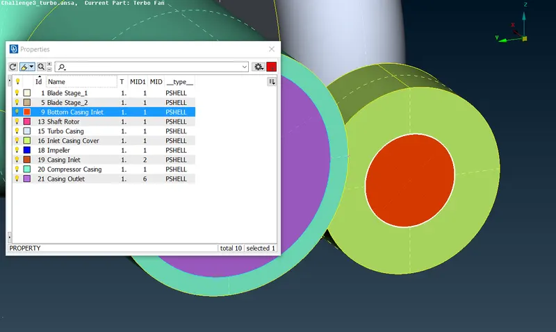
Bottom Casing Inlet
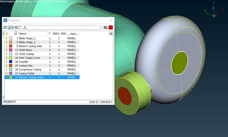
Bottom Casing Outlet
Surface Meshing
Compressor Casing surface mesh 5mm.
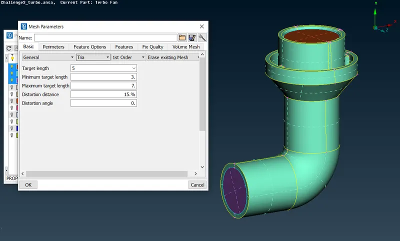
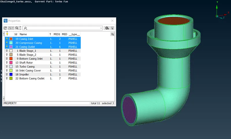
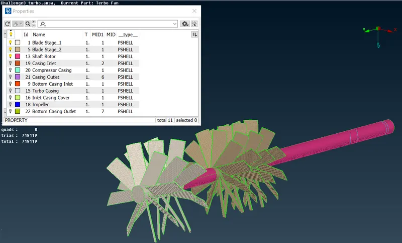
Blade Stage_1, Blade Stage_2, Shaft Rotor 1mm surface mesh.
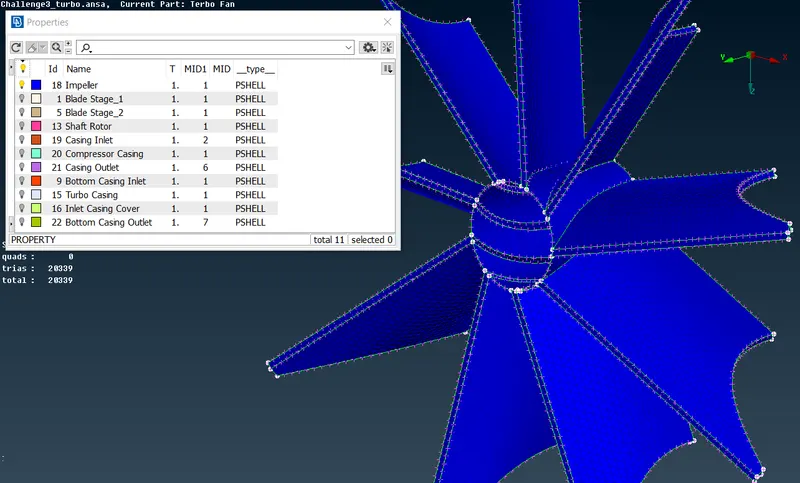
Impeller surface mesh 2mm.
Turbo Casing and Inlet Casing Cover 5mm surface mesh.
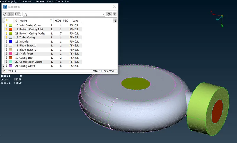
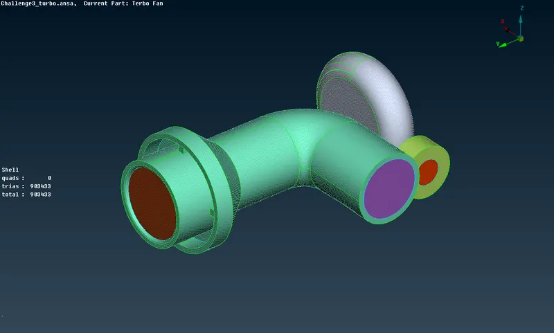
The Whole Geometry's surface was meshed successfully.
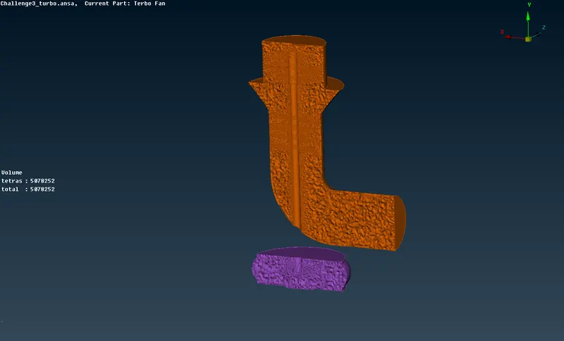
Volumetric Meshing
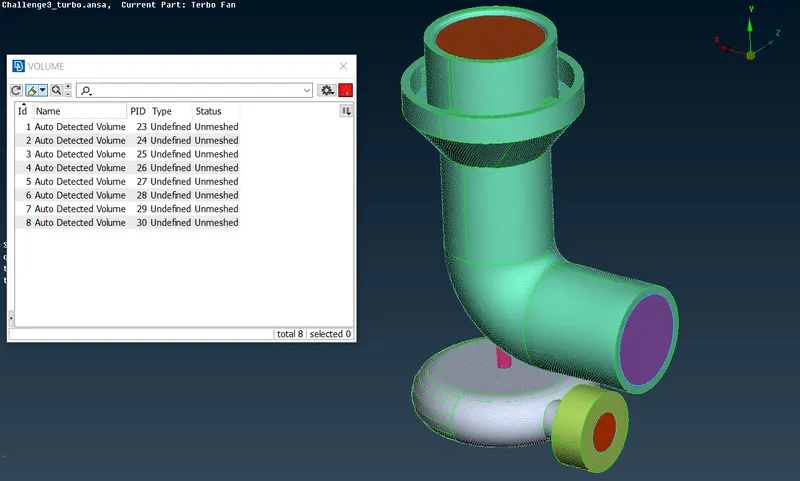
Before starting volumetric meshing we should delete volumes which contain solid material, measning geometry wall thicknesses. Only fluid zone volumes should be remained.
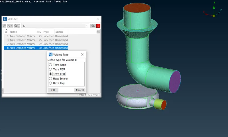
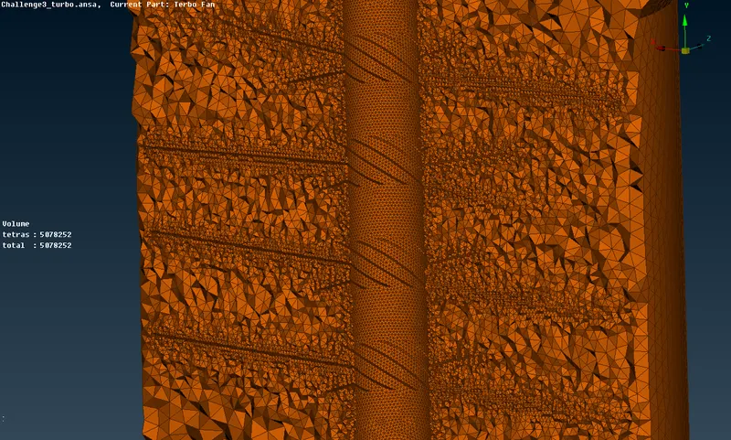
While meshing we should choose Tetra CFD for all volumes. Let's redo the same process for the all fluid volumes.
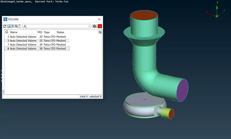
Cross section of the geometry
Conclusion
We successfully resolved all the problems the provided geometry had, Furthermore Surface and volumetric meshing went well.