Week 3:- BiW Fixture Design Methodologies Challenges
1.What is Design Methodology?
It is the method in which the steps followed during the concept designing stages of fixture design.
There are four stages of design methodology
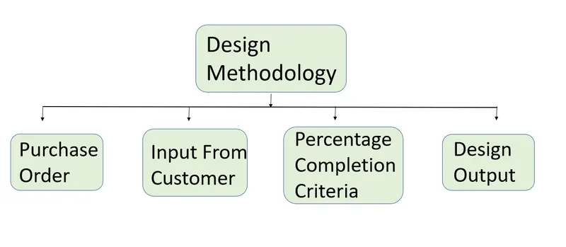
1)Purchase Order- Order from the customer for the start of the work.
A purchase order (PO) is a document that is issued by a buyer to a seller, indicating their intention to purchase certain products or services. On Design , POs are typically used to control the purchasing of products and services from suppliers, and are then retained for record keeping.
A PO may include the following information:
- The PO number.
- A description of the products and / or service being purchased.
- Technical details if required.
- Quantities.
- Any discounts to be applied.
- Agreed prices.
- payment terms.
- Shipment dates.
2)Input from Customer - Requiements and standards should be given by the customer to design.
- Functional Requirements - what are the functions to be performed on the design like welding, riveting etc.
- Preferred Standard Components - The components are given as a standard from the customer.
- Car Products - Data regarding the part drawing, Part list, Assembly process are given.
- Layout - Gives information about flow of parts through number of stations , no.of robots, tool accessories, loading & unloading heights etc.
- Ergo Data - Gives the information related to human behaviour (Required height, working safety etc).
- Weld Study - It gives information about no of weldings , type of weld gun needed.
- Standard Detailing Templates - Detailes templates from the customer for design.
3)Percentage Completion Criteria - The completion of work is calculated as per the percentage .
For eg:
0 to 25% - Input and Concept Design.
25 to 40% - Concept Approval and Simulation Check.
40 - 85 % - Design freezing and Detailing.
85 to 100 % - Quality Inspection and Final Dispatch.
4)Design Output - The output is 3D Models and 2D drawing tools. The tools are classified into utilized and non utilized tools.
The output should compile:
- Utilization of standard components
- Design must be simple and economical
- Must comply with all safety and ergonomic requirements.
- Design must be of damage free handling of product.
- Error proofing must be incorporated by proving proximity switches and rough locators.
- Weight of the moving pats must be minimum with maximum strength.
- Design must be easily accessible for maintenance and service.
- Motion control should be incorporated for moving parts.
- Validation of clamps and weld guns by the designer.
2.What are the inputs required from the customer to start designing a Fixture?
Input from Customer - Requiements and standards should be given by the customer to design.
Functional Requirements - what are the functions to be performed on the design like welding, riveting etc.The fixtures required according to the function.
- welding fixture - A welding fixture for a large industrial part. This fixture allows the part to spin on two different axis’ so the welder can reduce wasted motion and always weld in the flat position.
- Hemming fixture - In both the table top and hem die equipment, the hemming is performed in two stages – pre-hemming to 45° and then flattening. Both actions take place in the same fixture.
- Checking fixture - It is one of the inspection tools for measuring complex shaped parts. It is actually a scale to measure the most complicated shape parts and get the right one.
- Racks and frames - These are used outdoors to store materials, equipment, machines or tools should be designed, put together and maintained to support loads placed on them including wind, wind gusts and other environmental conditions.
Preferred Standard Components - The components are given as a standard from the customer.
- Standard like ABB, NAAMS,DESTACO,ZYTRAN,TUNKERS.
- Standard parts like Risers.L-Blocks, Retainers and Pins
- components like clamps, cylinders, slides, switches and sensors.
- weld guns, tip dressers and tool changers.
Car Products - Data regarding the part drawing, Part list, Assembly process are given.
- GD & T - Locating pins, Rest, clamp, dumps and slide information of each station.sequence of opening of clamps,dumps and side stroke information.
- Part List - List with the part name and its number
- CAD files of CAR Part - The required CAD files related to the design .
- Clamp Plan - Location of pins, rest, clamps, dump etc.
- Product Assembly Process Sheet - Detailed assembly of the given part.
Layout - Gives information about flow of parts through number of stations , no.of robots, tool accessories, loading & unloading heights etc.
Layout is concerned with proper positioning of componets when maintenance and access is considered. This is to be accomplished at mininmum cost.
Gives information about, Flow of parts, Station pitch, robot stations, Accessories like tool changer and tip dresser, Sub Assembly links, Platform Height, Loading or unloading sequence heights.
Ergo Data - Gives the information related to human behaviour (Required height, working safety etc).
Ergo data gives information about human behaviour, abilities and limitations and other characteristics to the design of tools, machines, tasks, jobs and environments for productive, safe, comfortable and effective human use.
Weld Study - It gives information about no of weldings , type of weld gun needed.
It includes
1)weld gun details,
2)weld matrix and weld points.
- Geo Weld Points
- Re-Spot Weld Points
Standard Detailing Templates - Detailed templates from the customer for design.
Standard templates for design and detailing the products.
3)What is the input we get from "Car Products"?
Car Products - Data regarding the part drawing, Part list, Assembly process are given.
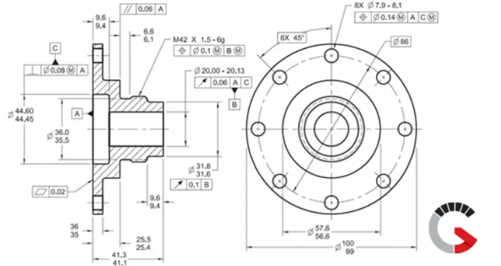
GD & T - Locating pins, Rest, clamp, dumps and slide information of each station.sequence of opening of clamps,dumps and side stroke information.
Geometric Dimensioning and Tolerancing (GD&T) is a system for defining and communicating engineering tolerances. It uses a symbolic language on engineering drawings and computer-generated three-dimensional solid models that explicitly describe nominal geometry and its allowable variation.
It tells the manufacturing staff and machines what degree of accuracy and precision is needed on each controlled feature of the part.
GD&T is used to define the nominal (theoretically perfect) geometry of parts and assemblies, to define the allowable variation in form and possible size of individual features, and to define the allowable variation between features.
- Dimensioning specifications define the nominal, as-modeled or as-intended geometry. One example is a basic dimension.
- Tolerancing specifications define the allowable variation for the form and possibly the size of individual features, and the allowable variation in orientation and location between features.
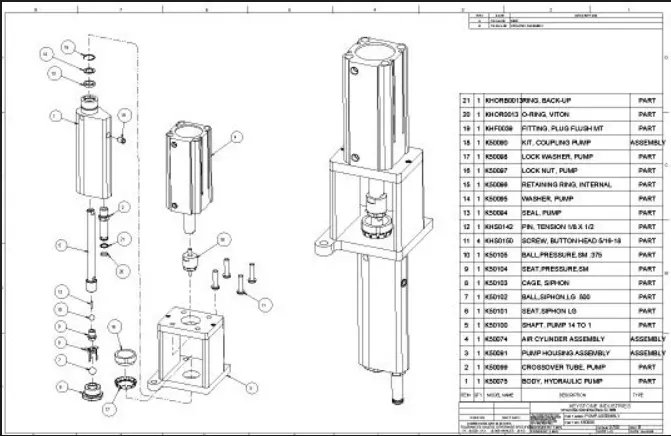
Part List - List with the part name and its number
The arrangement of the numbering of the individual sub assemblies, components and standard hardware. They are numbered from the bottom of the parts list upwards.
The relevant quantities and materials (missing) should also be stated.
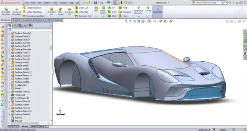
CAD files of CAR Part - The required CAD files related to the design .
The cad file extension is used for a 3D graphics file format, which is often associated with CAD (computer aided design) projects.
These CAD files are also known as CAD drawing files, and these may be generated by using CAD tools like the AutoSketch software from Autodesk.
Clamp Plan - Location of pins, rest, clamps, dump etc.
Clamping Device purpose is to hold work in the correct relative position in the fixture and to ensure that the job is not displaced under cutting forces. It is also necessary for clamping the jig to the work.
The most efficient scheme of clamping means that the clamping should be adequate and at the same time, the clamping device design should be such that the operating time of jig or fixture is least possible.
Thus for high rates of production, quick-acting clamps are essential whereas simple clamps may be adequate for small batches of work.
The clamp plan gives the exact location of pins , rest , clamps and dump.
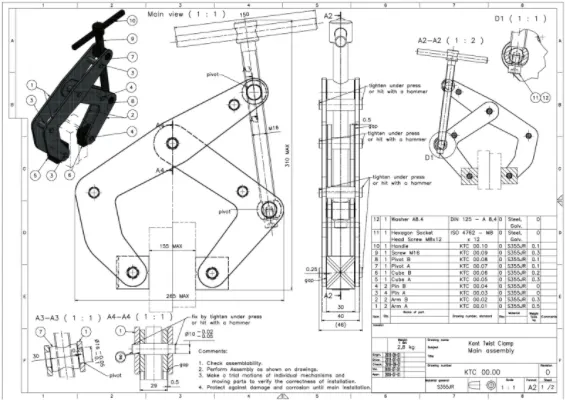
Product Assembly Process Sheet - Detailed assembly of the given part.
A processsheet describes the series of actions to be performed to achieve a particular task in the manufacturing or production process.
Thus, a process sheet is a document which has information and instructions for converting raw materials into finished components or specific assembly containing details such as material requirement, date and time, remarks, log in/out, etc.
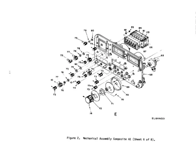
4)What is the Clamp plan?
Clamp Plan - Location of pins, rest, clamps, dump etc.
Clamping Device purpose is to hold work in the correct relative position in the fixture and to ensure that the job is not displaced under cutting forces.
It is also necessary for clamping the jig to the work.
The most efficient scheme of clamping means that the clamping should be adequate and at the same time, the clamping device design should be such that the operating time of jig or fixture is least possible.
Thus for high rates of production, quick-acting clamps are essential whereas simple clamps may be adequate for small batches of work.
The clamp plan gives the exact location of pins , rest , clamps and dump.
5)What is the purpose of a Layout?
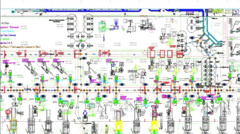
In a manufacturing assembly line set up, the work pieces in this design travel past the individual workstations on a conveyer.
As the individual workstations are passed, the worker at the station completes a small task, such as adding a sticker or tightening a bolt.
As these jobs are completed in turn, the completed product begins to form.
The design used in product layout differs from process layout and fixed-position layout in that the assembly line is arranged in a logical order of assembly.
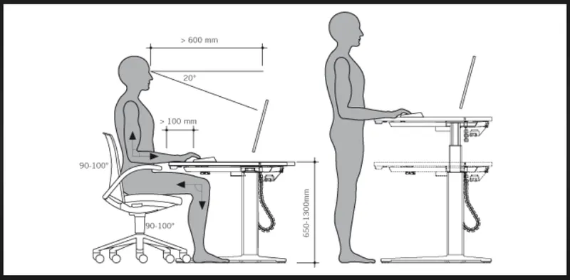
Having something that is called ergonomic means that the item has been designed to maximize productivity by minimizing effort and discomfort.
- The height of the fixture that the human can reach.
- The distance between the human and the fixture.
Weld Study - It gives information about no of weldings , type of weld gun needed.
It includes
1.weld gun details,
2.weld matrix and weld points.
- Geo Weld Points
- Re-Spot Weld Points
- Approved standard components are to be used whenever possible.
- Design must be as simple and economical as possible.
- Design must comply with all current safety and ergonomic requirements.
- Design must provide for controlled and damage free handling of product.
- Adequate error proofing provision must be incorporated into each design by providing proximity switches, rough locators etc.
- The weight of the moving parts must be kept to a minimum while maintaining maximum strength.
- Frames and structures are to be simple and sturdy.
- Design clearance and accessibility for routine maintainence and service.
- Motion control must be considered on any moving equipments.
- Designer is responsible to validate clamps and all weld guns.
10)What do you understand by structuring a design tree? How does it reduce errors during the design process?
Structuring a design tree implies to a process where all the assemblies and parts are named in a specific standard .
Different customers have different set of standards to structure a design tree.
It is an important process which help us to identify a specific partor assembly as to which project , tool or unit, it belongs to.
This helps us to avoid the errors during design study , manufacturing, assembly, inspection etc.
if the parts or assemblies are not named properly or the design tree is not structured properly, it will create confusion to understand the design and may create major possiblities of making an error.
Naming of a fixture or a unit or a part, gives the information as to which project or zone or assembly do they belong.
It can help us to identify the quantity of items of same type or different types that are being used in an assembly.
11)What are Units? Mention 5 types of units.
Units:
These are single units which are assembled together to form a Fixture.
The units are of various types based on the tool,
UTILIZED TOOL
SIMPLE UNITS
- Rest unit
- Fixed Pin Unit
- Retract Pin Unit
- Rough locator Unit
- Sensor Unit
- Base Unit
COMPLEX UNIT
- Slide Unit
- Dump Unit
NON - UTILIZED TOOLS
- Stands
- Takeout Trolleys
- Conveyors
- Turn Tables
- Some Grippers
Fixed Pin Unit - It is used to locate the car panel using Pins.
Retractable Pin Unit - It is designed to locate the car panel using pins, but the entire pin package parts will be mounted on the retractable pneumatic cylinder.
Rest Unit - It is designed to rest or support the car panel using NC blocks /Mylar/rest.
Clamp Unit - This unit is designed to clamp or hold the car panel ith NC blocks / Mylars /Rest by using a pneumatic clamp cylinder.
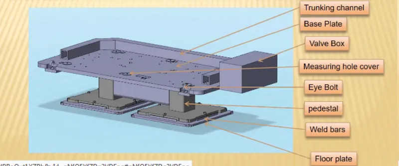
Base Unit - This unit is designed to mount all the other units (Clamp Unit, Pin unit, Rest Unit etc) of the tool , also other parts necessary for a tool like pneumatic valve box, trunking cable path will also be mounted onto a base unit.
12)Describe Fixed Pin units & their purpose?
Rough locators are elements that aid the operator to guide the car panels while loading onto the fixture and ensure a fool-proof assembly. the locating pins are used to locate a body part in a position sufficiently accurate to execute awelding process.
The body part is constrained by a set of appropriately locating pin so total constraint by locating pin should be fully constrained at all times to prevent any movement. (Usually two locating pins are enough to
properly locate the body part on one plane. one of the pins is round, and another one is diamond shaped.
This configuration will allow easier loading of body part. The end of each pin has a round or conical shape or is chamfered for the purpose of maintaining work ability such as ease of loading prevention of damage.
The taper lead angle is large, 60 degrees or less, for small-size body parts and manual operation. The difference between the locate hole in the panel or body part and the locating pin diameter should be -.05 mm and a tolerance for locating pin should be 0, +.05mm.
The dimension from the panel to the locating pin leading end 2straight area3 should be 1 mm.pins are available in numerous shapes and sizes in a design.
There are two configurations for position of locating pin:
i) keep two dowel pins for positioning as far apart from each other as possible
ii) Set the dowel pins in symmetrical positions .
One of the principal purposes of a locating surface is to locate and support the panel surfaces for performing a welding process. This is usually done with the datum surfaces that are reference for locating surface.
The dimensions of datum surface are decided by selecting a necessary cross-section from the part drawing. The shape of locating surface is a form of cross-section of panel. Locating surface is configured to receive panel for setting in a correct position and locating a body part from any surface such as flat, curved, or have an irregular contour.
In most applications, locating surface devices locate a panel by its external flat surfaces and flat area, such as% edges, flanges, steps, faces, shoulders, and slots

There are three types of shimming. These are one-way, two-way, and three-way shimming.
Blade or Adaptor plate - The plate which connects Riser to the Clamp cylinder is named Blade. This plate plays an important role in building the unit. The plate can be of any shape. But we need to keep in mind that the plate should be as compact as possible.
Block - This part is used as a connection between mylar and Blade. Generally, L blocks are used to provide shimming. It is not necessary that L blocks are only used for shimming, its uses changes as per the requirements, At some places, it is used just to connect one part to another. Similar to the L block one more block is used which is in the shape of T. So this block is called a T Block.
Riser - The part which is mounted on the base plate and holds a clamp or pin cylinder on it, is called Riser. Riser can be Standard Part or manufactured part, it varies from project to project. A riser can be a Single part or welded part. Standard risers also have various shapes and sizes.
Operator ergonomic while accessing all the spots. Construction of Rest Block: If standard Mylar has to be used (Few companies make standard height and length of steel blank with few holes and dowels for clamping) then select the proper blank size as per the requirement; consider 5 mm above the panel.
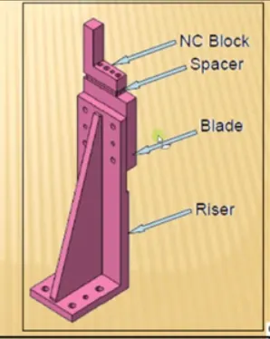
Shimming can be 1 directional, 2 directional, or 3 directional as per the NC cut.
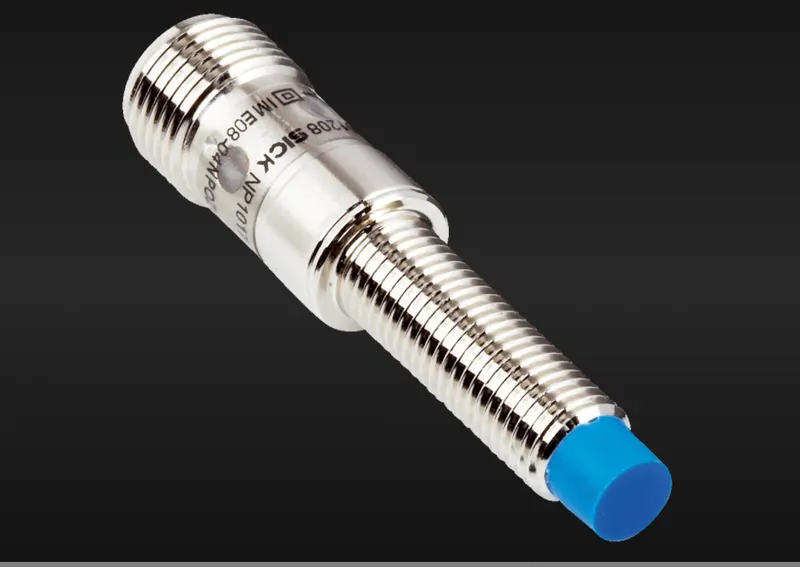
A proximity sensor is a sensor able to detect the presence of nearby objects without any physical contact.
A proximity sensor often emits an electromagnetic field or a beam of electromagnetic radiation (infrared, for instance), and looks for changes in the field or return signal.
The object being sensed is often referred to as the proximity sensor's target. Different proximity sensor targets demand different sensors.
For example, a capacitive proximity sensor or photoelectric sensor might be suitable for a plastic target; an inductive proximity sensor always requires a metal target.
Proximity sensors can have a high reliability and long functional life because of the absence of mechanical parts and lack of physical contact between the sensor and the sensed object.
The definition of a laser sensor is, it is an electrical device used to sense minute objects and precise positions.
This sensor uses a laser to produce light within a straight line. Its visible ray mark of the laser makes arrangement very simple. Laser light includes light waves with similar wavelengths.
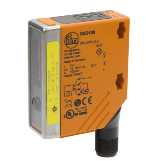
Photoelectric Sensor
A photoelectric sensor emits a light beam (visible or infrared) from its light-emitting element.
A reflective-type photoelectric sensor is used to detect the light beam reflected from the target.
A thrubeam type sensor is used to measure the change in light quantity caused by the target crossing the optical axis. Principle and major types

- Rough locators should be placed at the edges of the car panel, which it has to guide.
- Rough locators has to be placed in some angle of the car part edge with a minimum distance of 2-5mm from the edge of the car part.
- Rough locators should guide the psnel in pin arresting direction.
- Rough locators should start guiding the panel before 10 to 15 mm to the start of the engagement .
- It should be designed with two slots to mount for easy adjustment.
- It should be designed with entry angle for car panel entry.
- The slots should be in the direction of car part guiding.
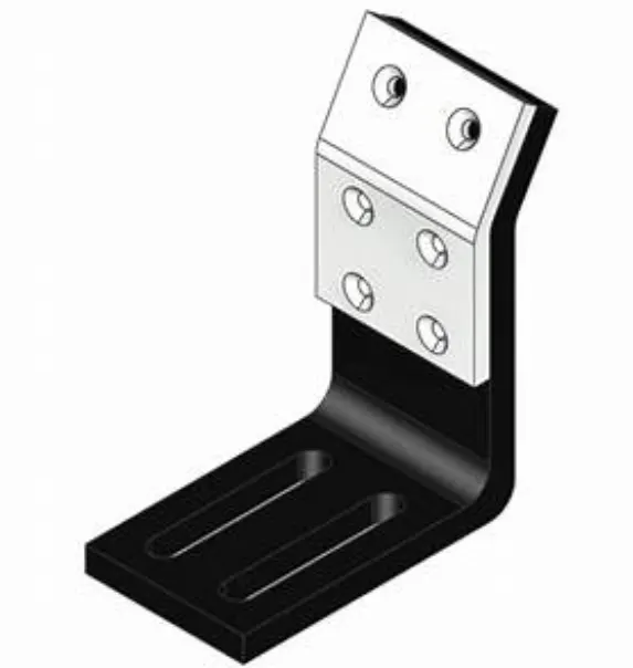
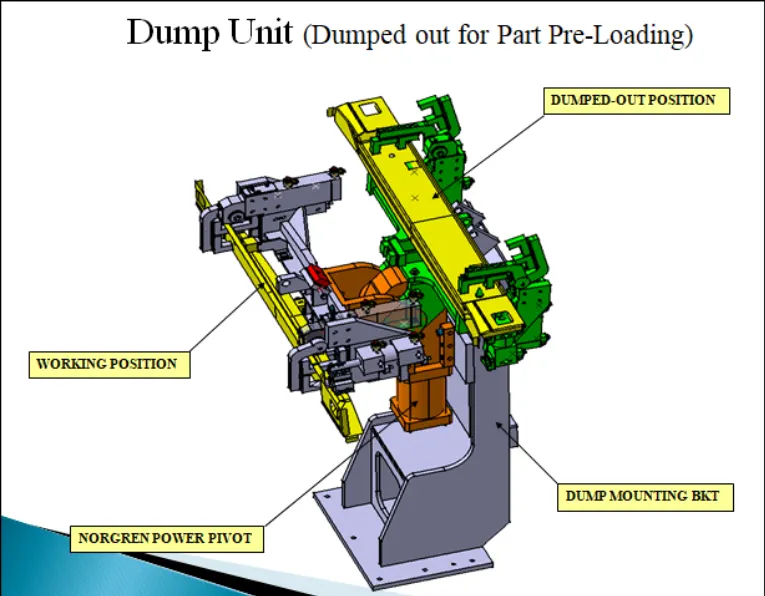
- If we have any constraint in assembling a component then we go fo for a dump unit.
- We can attach any one the units to the top of it .
- If we are not able to fix a part in normal way then we can use this.
- The dump unit is used when we have a geometrical constraint.
- The dump unit shall make use of two cylinders to perform a operation.
19) What is a Slide unit? Mention where Slide units are commonly used.
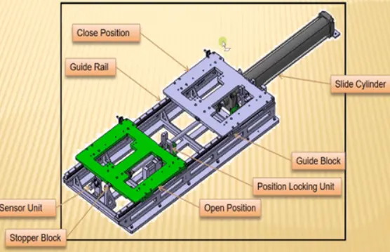
- Here we have sliding cylinder , with the use of that we can move the Guide blocks .
- The guide blocks move through the guide rails.
- The sensor units are used to monitor wheather the panels are loaded or not.
- Stopper block is used to stop the Guide block from further movement.
- The slide units are used where we have geometrical constraints to accomdate the blocks for fixing.