Week 3:- BiW Fixture Design Methodologies Challenges
1.What is Design Methodology?
DESIGN METHODOLOGIES:
In this methodology we learn about three design processes, we're going to study how do we proceed while doing a design. And one of the things that we take care of structuring or design tree so we'll be learning how to structure the design tree, and how to name the particular component or particular assembly, or the part of an assembly, which is very easy to read and very easy to understand.
Design methodologies are nothing but the steps followed during the concept designing stages of fixture design. The various stages of design methodologies are,
- 1.Purchase order.
- 2.Inputs from customer.
- 3.Percentage of completion criteria.
- 4.Design outputs.
- 1.Purchase Order:
A purchase order (PO) is a commercial document and first official offer issued by a buyer to a seller indicating types, quantities, and agreed prices for products or services. It is used to control the purchasing of products and services from external suppliers. Purchase orders can be an essential part of enterprise resource planning system orders. Purchase order is a order from customer for start of the work. After offer has been finalized customer will be releasing the LOI/PO(Purchase Order).
Once PO is released we have to start the work.
After PO from the customer we have to prepare the schedule.
Purchase order is the confirmation document from customer to proceed the committed work for them.
- Inputs from customer:
The inputs from the customers are as below,
Functional Requirements:
The purpose or the function of the fixture will be given as inputs from the customers like what are the process the fixture is going to do i.e welding, riveting, gluing or whether it is a checking fixture, etc.
Preferred standards:
As we know different companies follow different standards, we will be following the standards, we will be following the standards followed by the customers. By following standards the time of designing and manufacturing of parts will be saved, which will be automatically minimizing the time of the projects. As for the standards parts, it can be easily replaced from the used fixture to the new fixture which reduce the cost.
Car products:
The inputs we get from car products are GD&T, part list, cad files of car part, clamp plan, product assembly process sheet.
Layout:
Layout shows the entire assembly plan to understand the process. Layout provides the information of flow of parts, station pitch, robot stations, accessories like tool changers & tip dressers, sub assembly links, plat form height, loading/unloading sequence/height.
Ergo Data:
As same as preferred standards, different companies follow different standards of ergo data. We have to follow the customer standards of ergo data. The inputs of ergo data will given by the customer mostly in case of manually operated fixtures/manual fixtures. The ergo data is mainly used to make the operator comfortable which may lead to improve the efficiency in cycle time& production. Ergo data provides inputs like platform height, maximum & minimum reach from operator to fixture, maximum & minimum height of the fixture, whether the child parts/assemblies are visible while clamping or loading & unloading. Also provises information like loading height, working safety zone of operator, etc.
Weld study:
Weld study is the important inputs given by the customer. It gives details about the study of particulars gun that we use for welding. Also the dates like no/ of weld, position of weld in the components will be given. In short, weld study includes weld gun details, weld matrix & weld points.
Standard detailing templates:
This inputs include the detailing templates of 2D cad drawing as per the customer standards. So, we have to follow the detailing templates as per the customer standards.
3.Percentage of completion criteria:
Percentage completion criteria is basically schedule. What time that we can complete the entire process again this is more detailed. So when we are going to complete the in entire designing, then we're going to move on to simulation on all these subcategories would be considered in percentage completion criteria like a probability to when we can complete the entire fixture design.
It is followed in the designing stages & dispatch stages of welding fixtures. It helps to track or identify how much task completed & how much to go further for completing a fixture.
Inputs & concept design – 0 to 25%
Concept approval & simulation check – 25 to 40%
Design freezing & detailing – 40 to 85%
Check & final dispatch – 85 to 100%.
The above mentioned percentage are the percentages of stage wise completion criteria of the projects.
4.Design Output:
In BIW fixture design or any industry. We don't only just design a particular component and just give the CAD file to the customer, we have to give a lot of documents like 3d documents,2d documents, which is the detailing part, and as well as other factors as well like bom, bom bill of material and other documents as well about this particular component and their standards, all has to be submitted to the customer.
-
2.What are the inputs required from the customer to start designing a Fixture?
The inputs required from the customer to start designing a fixture:
- Fundamental requirements.
- Preferred standard components.
- Car products.
- Ergo – data.
- Weld study.
- Standard detailing templates.
- Functional Requirements:
The purpose or the function of the fixture will be given as inputs from the customers like what are the process the fixture is going to do i.e welding(spot or seam weld), gluing, riveting, hemming or whether it is a checking fixture or a storage racks etc.
It is one of the basic requirements to get from the customer to start designing a fixture.
- Preferred standards:
As we know different companies follow different standards, we will be following the standards, we will be following the standards followed by the customers. By following standards the time of designing and manufacturing of parts will be saved, which will be automatically minimizing the time of the projects.
As for the standards parts, it can be easily replaced from the used fixture to the new fixture which reduce the cost.
Some of the preferred standard components used in BIW fixtures are given below,
Standard like ABB, NAAMS, DESTACO, ZYTRAN, TUNKERS are used in design & manufacturing of fixtures.
Standard parts like Risers, L-blocks, retainers, pins, NC blocks, Shims, etc.
Components like clamps, cylinders, slides, switches, sensors, etc.
Weld guns, Tip dressers, Tool changers, etc. tip dressers are to sharpen the tip of the tools whereas tool changes are used in robots to do various process. As robots are too costly, tool changers are used.
ABB – It is a Robots manufacturing company.
Some example of description of standard robots are, Robust IRB 7600 robots, which can, hold the panels securely and accurately in place while IRB 6640 robots perform the welding.
The below picture shows the welding line is installed at great wall motors (GWM) recently opened and internationally acclaimed automotive plant in Tianjin, china. One of the factory’s most highly publicized and productive manufacturing lines is the ABB welding line, which comprises among other things a fleet of ABB robots and patented ABB framing and hemming technologies.
- Car Products:
The inputs we get from car products are: GD&T, part list, Cad files of car part, Clamp plan, product assembly process sheet.
GD&T: It provides information of locating pins, rest, clamp, damp & slide unit informationof each station. Also includes the information of sequence of openings of clamps, dumps & slide stroke information.
Part lists: It gives the lists of parts which are going to assembled in the fixture. The list contains the information of part number, part name, revision of fixture, part thickness, etc.
Clamp plan: Clamp plan provides the information of location of pins, Rest units, clamp unit, dump etc. It is the important input from customer. The clamp plan/position should not be changed without the knowledge of customer.
3D cad file: The 3D model of the car part will be given from customer. From that 3D model we will be developing our fixture design process. The 3D cad file will be in the format of step file (stp) or IGES file (igs).
Product assembly process sheet: It gives the information of stage wise assembly process like how the parts move from one assembly process like how the parts move from one assembly station to other after the completion of joining process.
- Layouts:
Layout shows the entire assembly plan to understand the process.
Layout provides the information of flow of parts, station pitch, robot stations, accessories like tool changers & tip dressers, sub assembly links, plan form height, loading/unloading sequence/height.
- Ergo Data:
As same as preferred standards, different companies follow different standards of ergo data. We have to follow the customer standards of ergo data.
The inputs of ergo data will given by the customer mostly in case of manually operated fixtures/manual fixtures.
The ergo data is mainly used to make the operator comfortable which may leads to improve the efficiency in cycle time & production.
Rivaa-Global - Manufacturing Engineering Services, Digital Manufacturing
Ergo data provides inputs like platform height, maximum & minimum reach from operator to fixture, maximum & minimum height of the fixture, whether the child parts/assemblies are visible while clamping or loading & unloading.
Also provides information’s like loading height, working safety zone of operator, etc.
- Weld Study:
Weld study is the important inputs given by the customer. It gives details about the study of particular gun that we use for welding.
Also the data’s like No. of weld, position of weld in the components will be given. In short, weld study includes weld gun details, weld matrix & weld points. Generally weld points will be given in spheres.
- Standard detailing templates:
These inputs include the detailing of 2D cad drawing as per the customer standards.
So we have to follow the detailing templates as per the customer standards.
-
3. What is the input we get from "Car Products"?
Inputs we get from car products include;
- GD&T.
- Part list.
- 3D cad file.
- Clamp plan.
- Product assembly process sheet
- 1.GD&T:
GD&T – Geometric Dimensioning & Tolerance.
It provides information on locating pins, rest, clamp, damp & slide unit information of each station. Also includes the information of sequence of openings of clamps, dumps & slide stroke information.
Tolerance important:
Assemblies – Parts will often fit together if their dimensions do not fall within a certain range of values.
Interchangeability – If a replacement part is used, it must be a duplicate of the original part within certain limits of deviation.
The relationship b/w functionality and size or shape of an object varies from part to part.
When to use GD&T:
- When part features are critical to a function or interchangeability.
- When functional gaging is desirable.
- When datum references are desirable to ensure consistency between design.
- When standard interpretation or tolerance is not already implied.
- When it allows a better choice of machining processes to be made for production of a part.
Datum in GD&T:
A datum is theoretical exact plane, axis or point location that GD&T or dimensional tolerances are referenced to you can think of them as an anchor for the entire part, where the other features are referenced from A DATUM feature is usually an important functional feature that needs to be controlled during measurement as well.
- Part lists:
It gives the lists of parts which are going to assembled in the fixture. The list contains the information of part number, part name, revision of fixture, part thickness, etc.
- 3D cad files:
The 3D model of the car part will be given from customer. From that 3D model we will be developing our fixture design process.
The 3D cad file will be in the format of step file (stp.) or IGES file (igs.) or sometimes it may be in part file (prt.).
- Clamp plan:
Clamp plan provides the information of location of pins, rest units, clamp unit, dump, etc.
It is the important input from customer. The clamp plan/position should not be changed without the knowledge of customers.
It gives the detail of the exact position of the clamping units.
- Product assembly process sheet:
It gives the information of stage wise assembly process like how the parts move from one assembly to other after the completion of joining process
It shows the sequence of operations/process to be done in a part or a panel.
Also what are the parts to be joined with the panel will shown in sequence.
From this sheet we can trace out the pending process which has to further go on for completion of part.
From this product assembly process sheet designer can understand the sequence for designing the fixtures.
-
4)What is the Clamp plan?
Clamp Plan - Location of pins, rest, clamps, dump etc.
Clamping Device purpose is to hold work in the correct relative position in the fixture and to ensure that the job is not displaced under cutting forces.
It is also necessary for clamping the jig to the work.
The most efficient scheme of clamping means that the clamping should be adequate and at the same time, the clamping device design should be such that the operating time of jig or fixture is least possible.
Thus for high rates of production, quick-acting clamps are essential whereas simple clamps may be adequate for small batches of work.
The clamp plan gives the exact location of pins , rest , clamps and dump.
-
5)What is the purpose of a Layout?
Basically, a layout in CAD represents a 2d space where the user has the ability to determine the size of the drawing board and edit the title block and also view multiple scenes of the object at the same time.In a manufacturing assembly line set up, the work pieces in this design travel past the individual workstations on a conveyer.
As the individual workstations are passed, the worker at the station completes a small task, such as adding a sticker or tightening a bolt.
As these jobs are completed in turn, the completed product begins to form.
The design used in product layout differs from process layout and fixed-position layout in that the assembly line is arranged in a logical order of assembly.
In some cases, this simple manufacturing layout is realized as a single manufacturing line with various workstations.The product layout design may be further broken down into smaller module lines which use several processes to complete one group task.For example, an auto manufacturer may have an assembly line module in which the car body is cleaned, primed, and painted in a single area of the plant, rather than being moved to three different workstations.6)What is Ergo data?Ergonomics is the science of the relationship between man and machinery and the equipment human beings use, and the working environment.
Having something that is called ergonomic means that the item has been designed to maximize productivity by minimizing effort and discomfort.For designing we have to consider ,- The height of the fixture that the human can reach.
- The distance between the human and the fixture.
These data should be given from the customer end.In general, there is no universally agreed list of ergonomics measures can be intervened in the design of manual assembly systems to reach the known goals that mentioned earlier.Most of studies concerned with design process for the manual works in assembly systems adapted ergonomics measures to identify the industrial environments factors which are to blame for problems associated with injuries.The ergonomics measures in interventions at work in order to eliminate or reduce the incidence and prevalence of (WMSDs) classified as technical measures (i.e., engineering controls), organizational measures (i.e., administrative controls), or individual measures (i.e., individual training or education).According to the national academy of science , most of factors that may affect the risk of (WMSDs) in assembly process depend both on work procedures and workstation design. Accordingly, the measures that are considered in this paper are those categorized as technical measures.7)What do you understand by Weld study?Weld Study - It gives information about no of weldings , type of weld gun needed.
It includes
1.weld gun details,
2.weld matrix and weld points.
- Geo Weld Points
- Re-Spot Weld Points
WELD GUN - A welding gun is a portable device used to achieve semi-automatic or automatic welds on pieces of metal. ...The most basic equipment setup in most semi- or fully automatic arc welding processes usually consists of the welding machine, which transfers or supplies power, and the welding gun that delivers the electrode.WELD MATRIX AND WELD POINTS - A Jig / Fixture is a device that holds, supports or is placed on a part to be machined or welded.It is a production tool made so that it not only locates and holds the work piece but also guides the tool as the operation is performed.In BIW we consider two type of fixture Tack / Geo Jig and Re-spot Jig. In Geo fixture tack welding done for all the parts to be assembled in that fixture.Standard guideline for Geo fixture , all the parts must be located with two locating pin ( Pin can be common for two or more parts. These Jigs have tight accuracy standard .In case of Geo fixture all the machine parts individually should be made with max tolerance of ± 0.02 mm . Where as positional accuracy of pin should be within ± 0.1 mm and of Mylar within ± 0.2 mm .In case of re-spot jig it may varies upto +_ 1.0 mm or more8. What are the criteria for percentage completion in the designing stage? Explain it in detail.
Percentage completion criteria is followed in the designing stages and dispatch stages of the welding fixtures. Certainly, here's an explanation of each stage in the welding fixture design process, along with the corresponding percentage completion criteria:
-
0% to 25% - Input and Concept Design:
- Description: The process of designing welding fixtures is still in the beginning stages at this point. Customer inputs, requirements, and specifications are gathered by designers. The structure and operation of the fixture are generally conceptualized.
- Activities: In this phase, major design considerations are identified and early sketching and conceptualizing are done.
- Goals: The design team should have a comprehensive understanding of the project requirements and initial suggestions for the welding fixture at the end of this stage.
-
25% to 40% - Concept Approval and Simulation Check:
- Description: The design concepts created in the earlier stage are improved upon and reviewed during this step. To determine the sustainability of conceptual designs, simulation and analysis are used.
- Activities: Simulators or prototypes are used to verify the design's viability and functionality once detailed design concepts have been developed.
- Goals: By the end of this stage, the design team should have approved concepts ready for further development, with confidence in their feasibility.
-
40% to 85% - Design Freezing and Detailing:
- Description: The important phase is where the last details and improvements to the selected design concepts are made. The welding fixture is precisely designed down to the individual dimensions, materials, and manufacturing requirements.
- Activities: Detailed drawings, specifications, and plans are created for every component of the welding fixture. Prototypes may be built and tested.
- Goals: The design should be finalized by this point, which means that no major modifications or revisions are expected. The fixture design is almost finished ready for manufacturing.
-
85% to 100% - Check and Final Dispatch:
- Description: The final step involves thorough quality checks and inspections of the finished welding fixture design. After addressing any outstanding problems or mistakes, the fixture is ready to be sent to the production or assembly line.
- Activities: Comprehensive quality assurance inspections are carried out, including functionality tests and conformance with design and safety standards. Finalized production and assembly documentation is available.
- Goals: The welding fixture design needs to be fully validated at this point, agree with all specifications, and should be ready for use in the manufacturing process.
Assuring an organized and systematic method to welding fixture design, these steps and their corresponding completion criteria serve to ensure quality, effectiveness, and consistency throughout the design process.
9. Brief about "Output" in design?- Unitized Tools: (multiple units on a common base) require two types of drawing sheets.
- Key sheet - An index of units and their placements on the tool base.
- Layout Sheet - A detailed drawing of individual units to include all of their components.
- Non-Unitized Tools: Tools that can stand alone and can be detailed completely on a layout sheet.
The output should compile following points:
- Approved standard components are to be used wherever possible.
- Design must be as simple and economical as possible.
- Design must comply with all current safety and ergonomic requirements.
- Design must provide for controlled and damage free handling of product.
- Adequate error proofing provision must be incorporated into each design by providing Proximity switches, Rough locators etc.
- The weight of the moving parts must be kept to a minimum while maintaining maximum strength.
- Frames and structures are to be simple and sturdy.
- Design clearance and accessibility for routhe maintenance and service.
- Motion control must be considered on any moving equipments.
- Designer is responsible to validate clamps and all weld guns.
- 10. What do you understand by structuring a design tree? How does it reduce errors during the design process?
- Structuring a design tree implies to a process where all the assemblies & parts are named in a specific standard.
- Different customers have different set of standards to structure a design tree.
- It is an important process which helps us to identify a specific part or assembly, as to which project, tool or unit, it belongs to.
- This helps us to avoid the errors during design study, manufacturing, assembly, inspection etc.
- If the parts or assemblies are not named properly or the design tree is not structured properly, it will create confusion to understand the design & may create major possibilities of making an error.
- Naming of a Fixture or a unit or a part, gives the information as to which project or zone or assembly do they belong.
- It can help us to identify the quantity of items of same type or different types that are being used in an assembly.
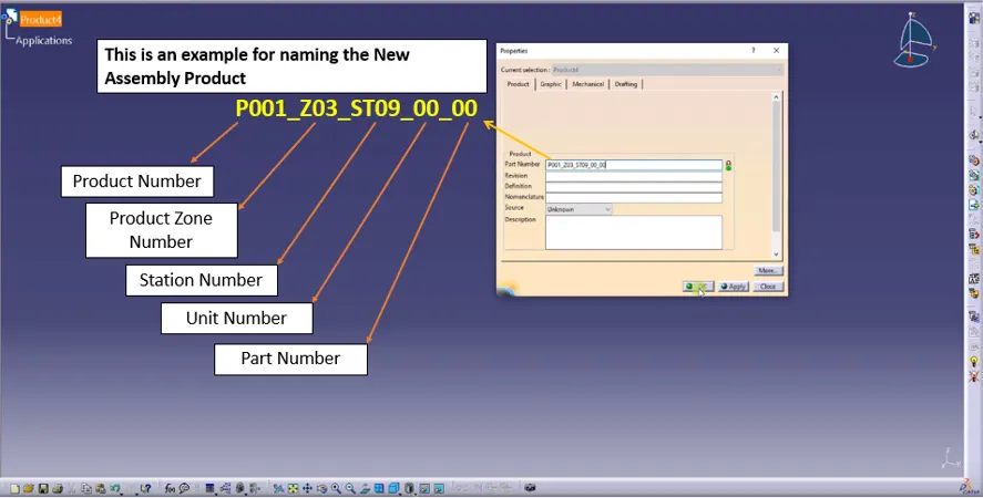
An example is provided for naming the new product.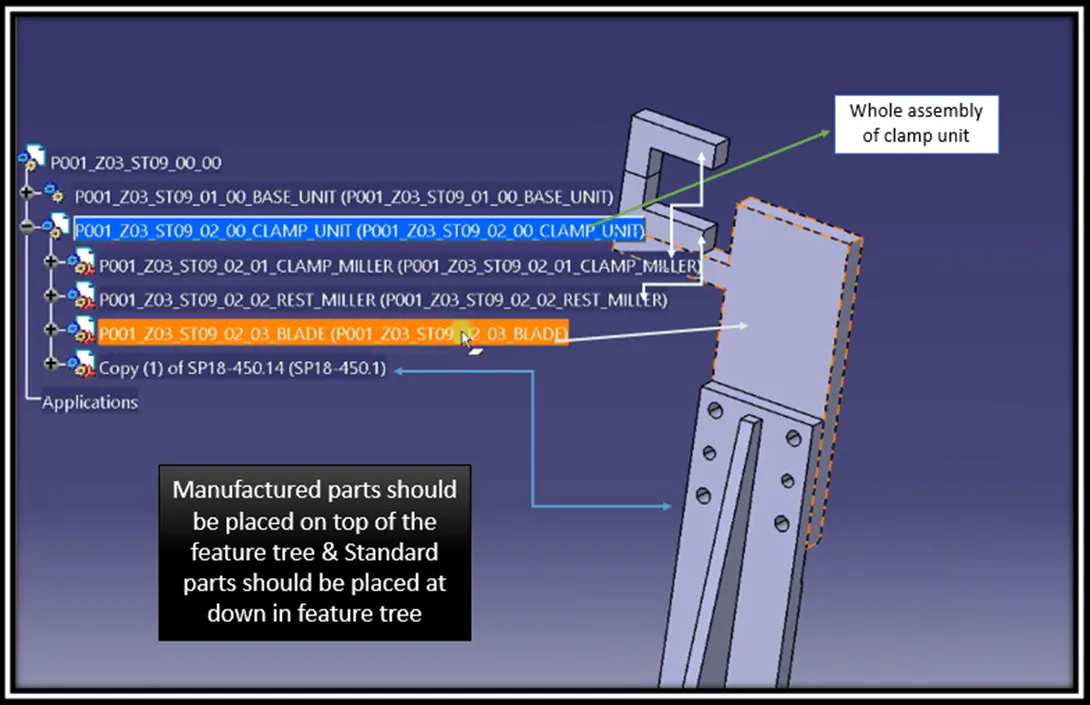
An example is provided for naming the new product with parts.Structuring a design tree refers to the systematic practice of naming assemblies and parts according to specific standards. This process is crucial for ensuring clarity and organization in design documents. Here's how structuring a design tree reduces errors during the design process:
-
Clear Identification: By following naming standards, each part or assembly is uniquely identified, making it easy to determine which project, tool, or unit it belongs to. This clarity helps designers and team members avoid confusion and ensures that everyone is on the same page.
-
Error Prevention: Properly named and structured design trees help prevent errors at various stages of the design process, including design study, manufacturing, assembly, and inspection. When components are clearly labeled and organized, it's less likely that mistakes will occur due to misinterpretation or oversight.
-
Consistency: Standardized naming conventions promote consistency throughout the design, reducing the chances of inconsistencies or discrepancies that could lead to errors.
-
Efficient Communication: Structured design trees facilitate effective communication among team members. When everyone uses the same naming conventions, it becomes easier to discuss and reference specific parts or assemblies, minimizing the risk of misunderstandings or errors.
-
Quantity Control: The structured design tree can also provide valuable information about the quantity of items used in an assembly, helping to ensure that the correct number of components is included and reducing the risk of assembly errors due to missing or excess parts
-
11.What are Units? Mention 5 types of units.
Units:
- A unit is a device that has a specified function, especially one forming part of a complex mechanism.
- A welding fixture is assembly of different types of units.
- As name refers, the different units will be only seen in the unitized tool.
- A units are classified into two, they are,
- Simple unit: In a simple welding fixture, the combination of these different units will be seen.
- Rest unit.
- Fixed pin units.
- Retract pin units.
- Rough locator unit.
- Sensor unit.
- Base unit.
Complex unit: In a complex welding fixture, in addition with some of the simple units these complex units will also seen
- Slide unit.
- Dump unit.
Five Types Of Units:
- Base unit:
Base unit is the unit designed to mount all other units such as clamp unit, pin unit, rest unit etc., of tool, also other parts necessary for a tool like pneumatic valve box, trunk cable path will also be mounted on to be a base unit.
Fixed pin unit:
- Fixed pin unit is a unit designed to locate the car panel using pins.table
- Pin, pin retainer, shims, blocks, blade, riser are the part of fixed pin units.
- Pin retainer is used to hold the pin firmly.
- Typically, the locating pins are used to locate a body part in a position sufficiently accurate to execute a welding process.
- The body part is constrained by a set of appropriately locating pin so total constraint by locating pin should be fully constrained at all times to prevent any movement.
Retractable pin unit:
- Retractable pin unit is unit designed to locate the car panel using pins, but the entire pin package parts will be mounted on the retractable pneumatic cylinder as shown in below fig 3.
- Retractable pin unit is the opposite of fixed pin unit which can be moved up & down also which can be retracted till certain distance.
- It is mainly used for unloading the complex panel after welding.
Clamping unit:
- Clamp unit is a unit designed to clamp or hold the car panel with NC block / Mylars by using a pneumatic clamp cylinder.
- Clamping unit is used to clamp the part which is to be welded after location using pin unit.
- Clamping is achieved with the help of pneumatic cylinders and clamp arms.
- Clamping arm, finger, rest, shims, standard riser, pneumatic cylinder are the parts of clamping unit in general.
Slide unit:
- Slide unit is found mostly in complex fixture, where the sliding mechanism will be involved.
- This type of unit used when there is some space constraints.
- Guide block, guide rail, position lock unit, stopper block, sensors are the parts of slide unit in general.
- Guide block & guide rail helps to the guide the slide unit. The rail should always be covered to protect against weld spatter & dust by a bellow or a sheet metal cover.
- Position lock unit helps the slide to be locked/clamped in the working position.
- Stopper block helps to stop/control the entire moving of a slide unit from certain distance, which is placed at the end of the guide rail.
- Sensors – The two end limits to be sensed externally by a proximity sensor.
PURPOSE OF FIXED PIN UNIT:
- As by 3-2-1 locating principle, the introduction of two pins helps to arrest the 6 degrees of freedom (4 axial & 2 radial movements) whereas other 6 degrees of freedom are arrested by introducing minimum three supports.
- Typically, the locating pins are used to locate a body part in a position sufficiently accurate to execute a welding process a welding process.
- The body part is constrained by a set of appropriately locating pin so total constraint by locating pin should be fully constrained at all times to prevent any movement.
12.Describe Fixed Pin units & their purpose? What are the different parts of a fixed unit?
DIFFERENT PARTS OF THE FIXED PIN UNIT:
The different parts of the fixed pin units are a
- Pin:
- It is used for the location purpose of the panel. Typically, the locating pins are used to locate a body part in a position sufficiently accurate to execute a welding process.
- The body part is constrained by a set of appropriately locating pin so total constraint by locating pin should be fully constrained at all times to prevent any movement.
- There are dozens of styles of locating pins that can be utilized in a design. One of the most common pins is a stepped pin with either small or large head.
- Round Pins:
These can be Screw secured (PNRS) or Grub Screw secured (PNRG) or Thread secured (PNRT) for Prototype build only. One of the most common pins is a stepped pin with either small or large head.
Diamond Pins:
The Diamond Shape is a critical feature that helps with machining inaccuracies and smoother locating operation. When two round head pins are installed onto one plate, the distance between two mounting holes must be extremely precise and even then, the work piece will not be placed on the base as easily as it would with the use of a diamond shape pin. These can be Screw secured (PNDS) or Grub Screw secured (PNDG) or Thread secured (PNRT) for Prototype build only.
- Pin Retainer:
Pin retainer is used to hold the locating pins firmly. Pin retainer is designed to hold the pin in its place and is also used as a rest for the pin. A counter hole drilled on which pin is fit
- Shims:
- In general, a shim is a thin and often tapered or wedged piece of material, used to fill small gaps or spaces between objects.
- Shims are typically used in order to support, adjust for better fit, or provide a level surface.
- Shims may also be used as spacers to fill gaps between parts subject to wear.
- Shims are the small parts which comes with the thickness of 0.1mm, 0.2mm, 0.5mm, 1.0mm etc.
- These will compensate the stack up tolerance which reflects at the mylars.
- We give tolerances to all parts of the fixture. Due to this tolerance the mylars will either lift up moves down from its defined position. To adjust the mylars for getting the defined position we use shims.
- Shims will be added above the mylar for adjusting according to tolerance.
Types of shim:
- Wood shim.
- Stone shim.
- Plastic shim.
- Metal shim.
- Paper shim.
- Riser:
Riser is a manufacturing part used to raise / height the assemblies of fixture.
One end of the raiser will be attached to the blade.
Raiser can be of two types. They are,
‘L’ type risers.
Square tube risers.
L TYPE RISERS: L type risers are of welded type. Where the stiffner will be added at the centre for support, as shown in the below figure the wedge shaped structure is known as stiffner which is used as a support/to withstand load.
13. What are the different parts of a fixed unit?
Fixed Pin unit is a unit designed to locate the car panel using pins.
And below are the different parts of a fixed pin unit in general.- Pin :
- It serves as the panel's location reference. The locating pins are typically used to precisely locate a body part so that welding may be done on it.
- A collection of properly placed locating pins is what constrains the body part, therefore entire constraint by locating pin should be totally limited at all times to prevent any movement.
- There are many locating pin designs that can be used in a design. A stepped pin with a tiny or large head is one of the most popular pins
An image of different pins are shown above
- Pin Retainer:
- The locating pins are held firmly in place by a pin retainer.
- The pin retainer serves as both a rest and a means of holding the pin in place. A pin-fitting counter hole that has been drilled.
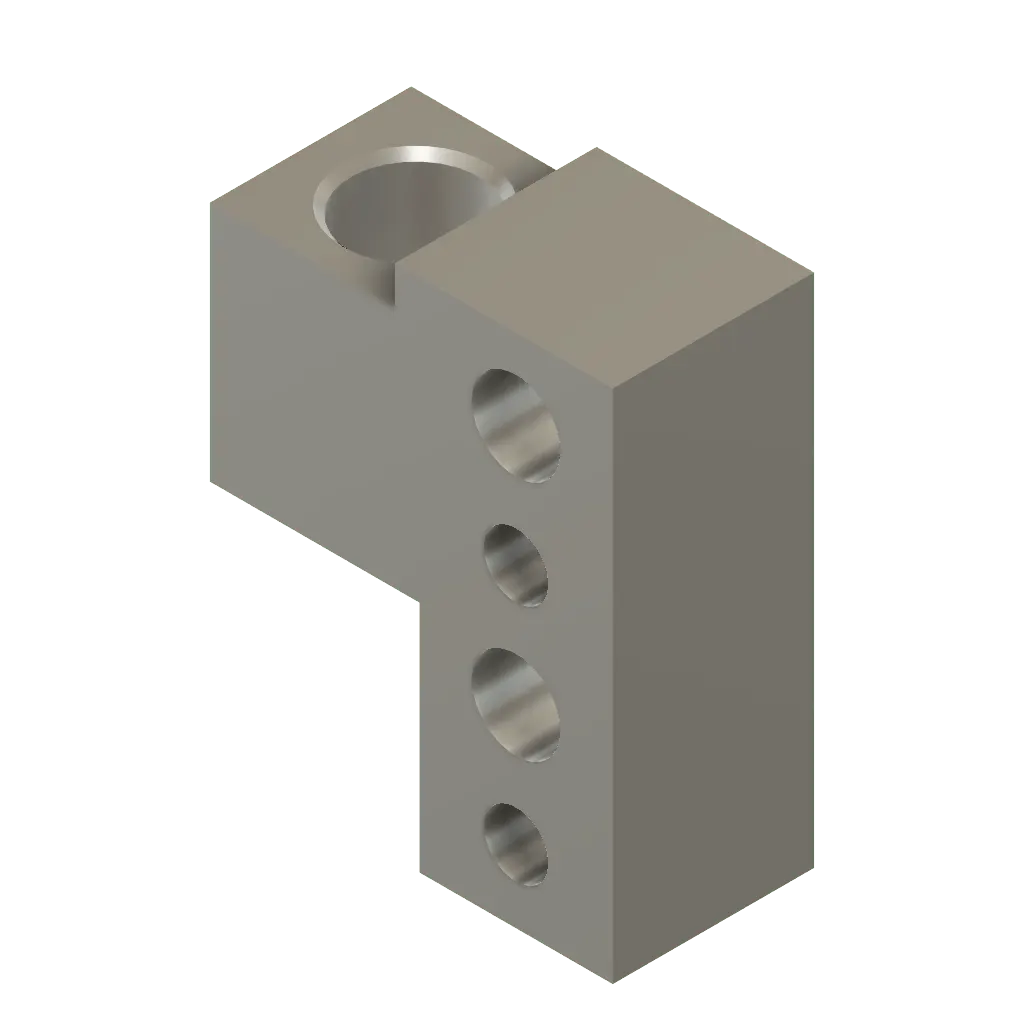
An image of Pin Retainer is shown above
- Shims / Spacers: Shims are small, flat pieces or strips of material that are fitted between components to change their tolerances, spacing, or alignment. Shims are used for a variety of tasks including alignment in a variety of sectors, such as automotive production and BIW (Body-in-White) fixture assembly units. Shims may be constructed from a range of materials, including metal (such as steel or aluminum), plastic, rubber, or composites. They are available in a range of sizes and thicknesses to satisfy various adjustment requirements. Shims are a useful tool in manufacturing and assembly operations because they assist maintain quality and efficiency while achieving precise and dependable outcomes.
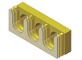
An image of shims is shown above - Block: Blocks are normally solid, frequently cuboid- or rectangular-shaped items made of a variety of materials, including metal, plastic, or composite materials. In industrial and manufacturing environments, blocks are used for a variety of tasks, including the installation of Body-in-White (BIW) fixture modules. Blocks can come in a variety of sizes, shapes, and designs depending on the particular specifications of the production process. When it comes to guaranteeing accuracy, stability, and efficiency in a variety of industrial and assembly applications, blocks are incredibly useful tools.
An image of different Blocks are shown above - Blade or Adaptor Plate:
- Blade are the plates which are attached to raiser.
- Blade is also attached or mounted with cylinders, arms etc.
An image of Blade is provided above
- Riser: Riser is a manufacturing part used to raise / height the assemblies of fixture. One end of the raiser will be attached to the blade.
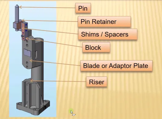
An image of Blade is provided above -
14. What is the purpose of making a Rest unit & describe its parts?
Rest Unit: A rest unit is a unit designed to rest / support the car panel using NC / Mylar / Rest.
And below are the different parts of a rest unit in general.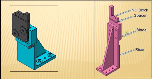
A "rest unit" is a specialized workstation or fixture designed to support and keep car body panels or components securely in place throughout various production processes, particularly in Body-in-White (BIW) fixture assembly. A rest unit's main objective is to make sure that the car panels are properly supported and positioned in order to avoid distortion, damage, or misalignment during welding, assembly, or inspection procedures. For panel support, rest units can use a variety of materials, including NC (Nylon Coated), Mylar, or other appropriate materials. I'll go into more detail about the many elements and parts that are frequently present in a rest unit below:
-
Support Surface: A rest unit features a specialized support surface designed to hold and align car body panels securely during manufacturing processes. This surface is contoured to match the panel's shape and is typically coated with materials like NC (Nylon Coated) or Mylar to prevent surface damage.
-
Rest Pins: Rest pins are integrated into the unit to engage specific features on the car panel, ensuring precise alignment and positioning. They can be adjusted to accommodate different panel sizes and configurations.
-
Height and Adjustment Mechanisms: Rest units are equipped with height and adjustment mechanisms that enable fine-tuning of the support surface and rest pins. These adjustments are crucial for accommodating variations in panel thickness and contour.
-
Clamping and Locking: Some rest units include clamping mechanisms, often pneumatic or hydraulic, to securely hold the car panel in place during manufacturing. Locking mechanisms are also used to prevent unintended movement once adjustments are made.
-
Load Distribution: Rest units are designed to distribute the load evenly across the panel, preventing localized stress and minimizing the risk of deformation or damage. This ensures that panels are properly supported and protected during the manufacturing process, contributing to quality and accuracy.
In conclusion, a rest unit is an essential part in assembling BIW fixtures in the automotive industry. It contributes to the precision, quality, and efficiency of welding, assembly, and inspection activities by providing critical support and accurate positioning for automobile body panels. Rest units are adaptable tools that can accommodate various panel kinds and sizes while guaranteeing the protection and integrity of the panels thanks to the presence of materials like NC or Mylar coatings and the insertion of adjustment and clamping mechanisms.
-
A proximity sensor is a sensor able to detect the presence of nearby objects without any physical contact.
A proximity sensor often emits an electromagnetic field or a beam of electromagnetic radiation (infrared, for instance), and looks for changes in the field or return signal.
The object being sensed is often referred to as the proximity sensor's target. Different proximity sensor targets demand different sensors.
For example, a capacitive proximity sensor or photoelectric sensor might be suitable for a plastic target; an inductive proximity sensor always requires a metal target.
Proximity sensors can have a high reliability and long functional life because of the absence of mechanical parts and lack of physical contact between the sensor and the sensed object.
The definition of a laser sensor is, it is an electrical device used to sense minute objects and precise positions.
This sensor uses a laser to produce light within a straight line. Its visible ray mark of the laser makes arrangement very simple. Laser light includes light waves with similar wavelengths.
Photoelectric Sensor
A photoelectric sensor emits a light beam (visible or infrared) from its light-emitting element.
A reflective-type photoelectric sensor is used to detect the light beam reflected from the target.
A thrubeam type sensor is used to measure the change in light quantity caused by the target crossing the optical axis. Principle and major types
- Rough locators should be placed at the edges of the car panel, which it has to guide.
- Rough locators has to be placed in some angle of the car part edge with a minimum distance of 2-5mm from the edge of the car part.
- Rough locators should guide the psnel in pin arresting direction.
- Rough locators should start guiding the panel before 10 to 15 mm to the start of the engagement .
- It should be designed with two slots to mount for easy adjustment.
- It should be designed with entry angle for car panel entry.
- The slots should be in the direction of car part guiding.
18. What is a Dump Unit and what are its functions?
Mechanical systems known as dump units are used in a variety of sectors to efficiently handle and transfer commodities. This article gives a concise introduction of dump units, describing their many functions and outlining their goal.
Dump units, also known as dump mechanisms, are hydraulically powered mechanical apparatuses. By raising and lowering cargo beds or containers, they primarily serve to permit controlled material discharge and enable accurate loading, unloading, and dumping.
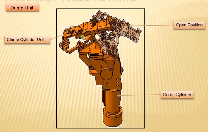
Dump units have important functions in the manufacturing process of BIW:
- Material Handling: Ensure effective assembly by optimizing the transfer of bulk materials throughout the BIW production process. This will reduce manual labor requirements and improve material distribution.
- Waste Management: Improve waste management by making it easier to dispose of materials in designated areas, which will improve the manufacturing facility's cleanliness and waste management effectiveness.
- Component Transfer: Make it possible for the controlled and effective transfer of BIW parts and components, making sure they are placed correctly for welding, assembly, or other processing.
- Improving logistics and material flow inside the BIW manufacturing environment can help to support just-in-time manufacturing procedures and minimize production delays.
19. What are slide units? Mention where slide units are commonly used?
Slide units, also known as linear slides or linear motion systems, are critical mechanical components extensively employed in a wide array of industrial applications. This report provides an overview of slide units, elucidating their characteristics, primary functions, and their significance within the context of Body-in-White (BIW) assembly lines in the automotive industry.
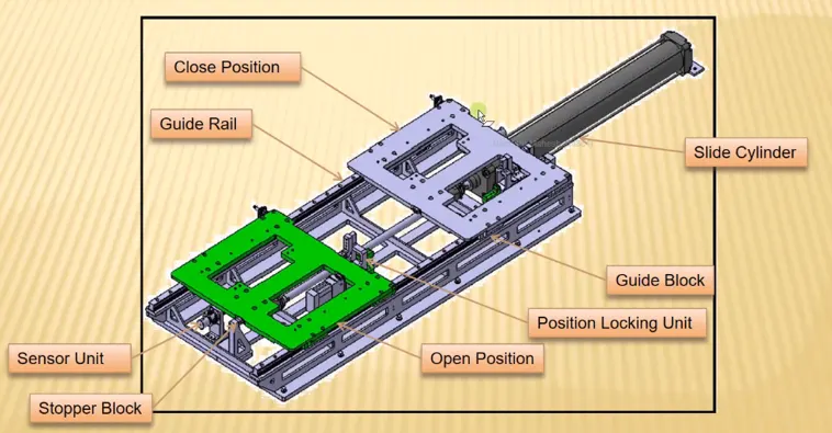
Slide units are mechanical devices designed to facilitate controlled linear motion or translation of objects along a fixed path. They typically incorporate sliding components, such as bearings or guides, to ensure precise and smooth movement.
Common Uses of Slide Units:
- Manufacturing and Automation: In manufacturing and automation operations, slide units are frequently used to enable the precise positioning and movement of machinery parts, conveyor systems, and robotic arms.
- Machine Tools: Slide units are essential to the operation of machines like lathes, milling machines, and CNC equipment in the machine tool industry, maintaining the accuracy of shaping and cutting operations.
- Packaging and Material Handling: Slide units are essential to the packaging industry because they allow for controlled movement on conveyor systems, product assembly lines, and packaging machinery.
- Medical and Laboratory Equipment: Slide units are essential components of laboratory and medical equipment, helping with activities like moving the microscope stage and handling samples for precise medical treatments.
- Aerospace and Automotive: Slide units aid in the precise movement of aircraft parts in aerospace applications, and they support testing and assembly line equipment in the automobile sector.