Week 3:- BiW Fixture Design Methodologies Challenges
BIW FIXTURE DESIGN METHODOLOGIES
Q.1)
DESIGN METHODOLOGY
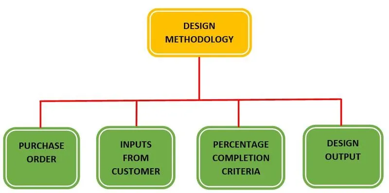
Design Methodology is the process which has the four stages shown above, which follows stage by stage during Designing of a product.
The Four stages are shown below: -
- Purchase Order.
- Inputs from Customer.
- Percentage Completion Criteria.
- Design Output.
PURCHASE ORDER
A purchase order (PO) is an official document, created by the buyer, which authorizes a purchase transaction for goods or services from a supplier.
POs play an important role in controlling business purchases. A professional PO process builds robust supplier relationships and provides an audit trail of all transactions.
It is generally assisted by some level of automation that helps speed up the process, improves communication, and minimizes financial risk.
The following are the stages of placing an Purchase Order: -
- Creating the Purchase Requisition (PR)
- Issuing the PO
- The supplier approves the PO
- Purchaser records and files the PO, awaiting delivery
- Approval and payment
INPUTS FROM CUSTOMER
Designing a new product is no different. To ensure that your output (final product) is appropriate (or epic), you must start by determining all of your inputs (design inputs) because they will guide & drive the design process.
Design inputs are the technical reflections of your customers needs and they represent your customers requirements for the final product relating to safety, performance, functionality, quality, reliability and the intended use of your product.
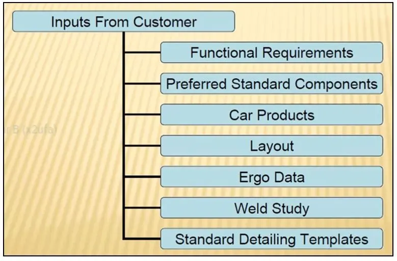
The basic inputs received from the customer for designing a fixture is shown in below diagram: -
PERCENTAGE COMPLETION CRITERIA
Percentage completion criteria is a schedule, showing the different stages of design completion of a fixture. It helps to track or identify how much task completed & how much to go further for completing fixture design.
The distribution of Design completion in percentage wise is shown below: -
1.) Inputs & concept design – 0 to 25%
2.) Concept approval & simulation check – 25 to 40%
3.) Design freezing & detailing – 40 to 85%
4.) Check & final dispatch – 85 to 100%
DESIGN OUTPUT
Design outputs are the documents that show that the design inputs have been implemented. These documents serve as guidance for consistent production and assembly of future products. So, when you generate the finalized version design output records, you should be able to assemble the device with the same design, quality, specification, and functionality on consistent basis. Design outputs will include records such as:
- Drawing
- Design specification
- Manufacturing plan and instructions
- Component specification, and
- Production and assembly instructions.
Q.2)
INPUTS REQUIRED FROM THE CUSTOMER TO START DESIGNING A FIXTURE
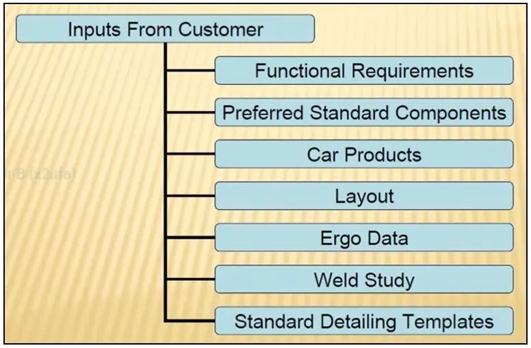
The inputs required from the customer to start designing a fixture is sown in below drawing: -
Functional Requirements
Functional requirement is the basic inputs obtained from the customer to design a fixture. The developed fixture should meet its functional objective by performing the operations on the product like welding, hemming, contour checking and other additional functions which is installed on the final fixture assembly, as per customer’s requirement.
Preferred Standard components
Fixture Design and its manufacturing is custom engineered as per the customer requirement.
A fixture manufacturer being as an OEM, cannot manufacture all the parts of fixture assembly within its factory. Few of the standard components are procured directly from the sub-vendors / sub-suppliers to fulfil the needs.
The Standard parts that are readily available in the market are shown below: -
- Standard suppliers like ABB, NAAMS, DESTACO, ZYTRAN, TUNKERS are used in design & manufacturing of fixtures.
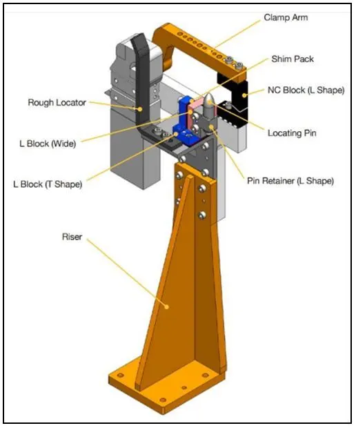
- Standard parts like Risers, L-blocks, retainers, pins, NC blocks, Shims, etc.
- Components like clamps, cylinders, slides, switches, sensors, etc.
- Weld guns, Tip dressers, Tool changers, etc. tip dressers are to sharpen the tip of the tools.
The above semi-finished parts plays an important role for reducing the delay of the fixture manufacturing.
Car Products
The Car Products includes the below parts: -
- GD & T
GD & T provides the information of locating pins, Rest, Dumps & Slide information for each station. The sequence of clamp opening, dumps and slide stroke information is provided through GD & T Geometrical feature sets.
- Parts list
Parts list is the detailed list consisting the sub-assemblies and sub-parts, which are associated with the final fixture assembly. The Parts list also contains the part number and part name of the components. The revisions made for the particular sub-part is also indicated in the part list.
- Clamp plan
Clamp plan provides the information of location of pins, Rest units, clamp unit, dump etc. It is the important input-requirement to be provided by customer.
- Product Assembly process sheet
It gives the information of stage wise assembly process like how the parts move from one assembly process like how the parts move from one assembly station to other after the completion of joining process.
Layout
Layout provides the information of flow of parts, station pitch, robot stations, accessories like tool changers & tip dressers, sub assembly links, plan form height, loading/unloading sequence/height.
Ergo Data
Ergo data provides inputs like platform height, maximum & minimum reach from operator to fixture, maximum & minimum height of the fixture, whether the child parts/assemblies are visible while clamping or loading & unloading
Weld Study
Weld study includes details of weld gun, weld matrix and weld points. The inputs to design the weld gun should be requested from customer to meet their requirement.
Standard Detailing templates
The 2D detailing of the final fixture assembly is prepared and submitted to customer, as per the requirement asked in the pre-design stage.
All the design protocols and standards has to be followed in order to comply with the customer’s specification.
Q.3)
INPUTS FROM "CAR PRODUCTS"
The Inputs arrived from the Car Products are shown below: -
- GD&T.
- Part list.
- CAD files of Car part.
- Clamp plan.
- Product assembly process sheet.
GD&T
GD&T consists of dimensions, tolerances, definitions, symbols, and rules that enable the design engineers to convey the design models appropriately. The manufacturing unit uses the language to understand the design intent.
The crucial concepts, which includes are shown below:
- Machining tolerances: Tolerances mean the allowable amount of deviation from the proposed drawing. Machined parts look flat and straight through the naked eye, but if viewed with callipers, one can find imperfections all over. These imperfections or variations are allowed within the tolerance constraints placed on the parts. Tolerances should be kept as large while preserving the functions of the part.
- The Datum Reference Frame: DRF is the most important aspect of GD&T. It is a three-dimensional cartesian coordinate system. It’s a skeletal reference to which all referenced geometric specifications are related.
- GD&T Symbols: It is essential to be familiar with numerous symbols and types of applied tolerance in GD&T. The language of symbols makes it easier to interpret designs and improve communications from the designer to the shop. By using GD&T standard, the design intent is fully understood by suppliers all over the world.
- Feature Control Frame: The feature control frame describes the requirements or instructions for the feature to which it is attached. A feature control frame contains only one message. If a feature needs two messages, the feature would need the corresponding amount of feature control frames for every message required.
- Basic Dimensions: Basic dimensions are exact numerical values in theory, which defines the size, orientation, form, or location of a part or feature.
- Material Condition Modifiers: It is often necessary to state that a tolerance applies to a feature at a particular feature size. The Maximum Material Condition (MMC) allows an engineer to communicate that intent.
It provides information of locating pins, rest, clamp, damp & slide unit information of each station. Also includes the information of sequence of openings of clamps, dumps & slide stroke information.
PART LIST
As explained earlier, part list is the list of all the parts like sub-assemblies and sub-parts, which forms the part of the main assembly.
Here the main assembly is FIXTURE.
The Fixture assembly will have the complete part list with its part number, part name, revision number and last modified date.
CAD FILES OF CAR PART
To Design a fixture for a certain section of automobile, we have to ask the CAD files from the customer.
The CAD file in 3D / 2D version has to be received, in the respective format suitable to be easily opened through the desired design tool.
Based on the received CAD file, the design and developing of the fixture takes place.
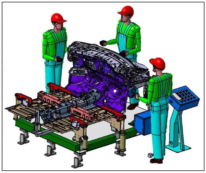
CLAMP PLAN
Clamp plan provides the information of location of pins, rest units, clamp unit, dump, etc.
It is the important input received from customer for understanding the clamp has to be designed. The clamp plan/position should not be changed without the approval from customer.
PRODUCT ASSEMBLY PROCESS SHEET
Product assembly process sheet represents how the sub-parts of a sub-assembly are assembled.
The different steps involved in performing the assembly is shown in the process sheet.
For completing the final assembly of the fixture, the different stages of sub-assemblies and their flow path are shown, in order to avoid the error for assembly failure.

Q.4)
CLAMP PLAN
Clamping Device purpose is to hold work in the correct relative position in the fixture and to ensure that the job is not displaced under cutting forces. It is also necessary for clamping the jig to the work.
The most efficient scheme of clamping means that the clamping should be adequate and at the same time, the clamping device design should be such that the operating time of jig or fixture is least possible. Thus for high rates of production, quick-acting clamps are essential whereas simple clamps may be adequate for small batches of work.
For designing of efficient clamping devices, the following points should be considered
- Clamps should always contact the work at its most rigid point to avoid bending or damage of part by the clamping force. It the clamping force at any point could bend the part, it must be supported suitably at that point
- Clamps should be positioned such that they do not interfere with the operation of machine/tool and enable operator to work easily and safely.
- Tool forces generated by cutting action should help in holding the work piece instead of lifting or tilting it. The tool forces should be directed at solid part of the tool body.
Clamp plan:
Clamping plan is the plan which defines the location of the clamp while performing the operation to ensure the geometry of the assembly.
We have to design fixture as per the input received from the customer , to avoid change in the clamp plan.
It provides information regarding to the location of pins, Rest, Clamps, Dumps etc. The coordinates are also mentioned in the clamp plan so the design team can take the coordinates directly & start the designing of the fixture.
Q.5)
PURPOSE OF A LAYOUT
The purpose of a process layout is to understand the information about where the fixture & robots are been placed, working area covered by the robot, what are the fixtures assigned for the robots to do the process, etc.
Process layout shows the entire assembly plan to understand the process.
Process layout and assembly are accomplished by developing a commercial database for modular fixture components and the search strategy to and the feasible locating and clamping positions in all types of workpiece orientations. The search strategy is specially designed on the basis of fixed rules, part geometric, and dimensional constraints, and a fixture database to select the appropriate modular fixture components and their feasible positions with respect to the selected workpiece.
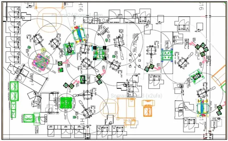
Layout provides information of: -
- Flow of parts – The flow of car panels, which travels from one work station to another work station.
- Station Pitch - The distance between two stations is known as station pitch. It shows the space constraints between the two stations, which shows in layout.
- Robot Stations - It shows the position where the robots & their accessories placed, which is shown in the layout
- Tool changer – The tool changer has the set of tools, where each tool has its own functional requirement.
- Sub assembly link: Sub assembly link is nothing but the link between the assembly fixtures & the main assembly line. It shows that how the sub assembly fixtures are linked with the main assembly line.
- Platform Height – is the height of the fixture assemblies.
Q.6)
ERGO DATA
Reliable assembly tooling must be able to hold components and subassemblies in an accurate and repeatable position, prevent undesired motion of components, and avoid posing interference problems in assembly tasks.
Computer-aided design techniques, heuristic algorithms, and Expert Systems have been developed and implemented to optimize certain aspects of assembly tooling design.
The Ergonomics plays an important role in handling the multiple tools of a fixture assembly.
The right ERGO DATA helps us to identify the required area of movements that has to be made with the help of upper limbs and hand, in order to perform the task at comfortable and efficient manner.
- ERGO DATA provides information of loading height, working safety zone of operator, amount of lighting required to have a fair visibility on performing the assigned task.
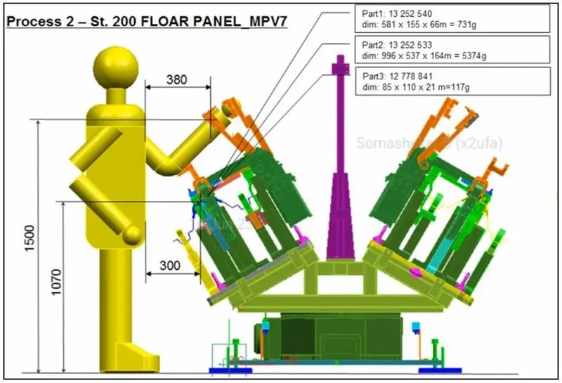
Advantages of Ergonomics in handling fixtures:-
- Increased savings
Fewer injuries, more productive and sustainable employees and fewer workers’ compensation claims.
- Fewer employees experiencing pain
Implementing ergonomic improvements can reduce the risk factors that lead to discomfort.
- Increased morale
Attention to ergonomics can make employees feel valued because they know their employer is making their workplace safer.
- Reduced absenteeism
Ergonomics leads to healthy and pain-free workers who are more likely to be engaged and productive.
Q.7)
WELD STUDY
Weld study gives the study of particular weld-gun that is used for welding the panels of the vehicle.
The Weld study provides the - No. of spots to be welded, sequence of weld, position of weld-spots in the components. In short, weld study includes weld gun details, weld matrix & weld points.
Generally, the weld points will be given in spherical shape.
Red sphere represents the Geo spot weld points whereas Green sphere represents the Re-spot weld points as shown in the below image.
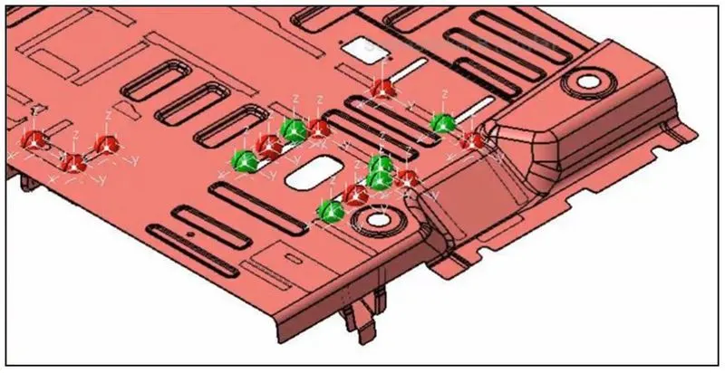
The weld points are classified as,
- Geo weld points:
The Geo weld points are indicated on the Geo fixture.
These welds will determine the position of the panels as per the given data in drawing.
The geo weld points are represented in red sphere in the weld study inputs given by the customers.
- Re-spot weld points:
The Re-spot weld points are planned on the re-spot tool.
These welds will determine the strength/stiffness of the panel/components.
The Re-spot weld points are represented in green spheres in the weld study inputs given by the customers.
Q.8)
CRITERIAS FOR PERCENTAGE COMPLETION IN THE DESIGNING STAGE
The percentage completion report in the design stage is the important report, which explains how the designing stages completes from the starting phase to ending phase.
The Four stages of percentage completion criteria is shown below:-
a.) Input & concept design.
b.) Concept approval & simulation check.
c.) Design freezing & detailing.
d.) Check & final dispatch.
INPUT AND CONCEPT DESIGN
Input and concept design is the first stage, which helps to understand the design requirement of customer, and laying down of the basic concept of the design.
The design concept is usually arrived by referring to the similar type of design execution done in past records.
Based on the old reference concept, the new design is generated by fabricating the old data matching to the customer requirement.
The amount of percentage accommodated by the input stage varies between 0-25%.
CONCEPT APPROVAL & SIMULATION CHECK
Once the designing of concept is completed, the approval of the design concept has to be made by discussing with the customer.
The design concept is submitted to the customer for reviewing and providing approval to proceed for next stage.
During the review stage, the customer may raise query if any deviation is considered from the requirement asked for.
The amount of percentage accommodated by the concept approval is between 25-40% after the concept design stage.
DESIGN FREEZING & DETAILING
Once the customer approves the design concept and simulation of the design, then the next stage is DESIGN FREEZING.
In design freezing, the approved design concept by customer is freezed. The freezing of the design states that, there will be no further revision and changes in the design concept from the seller end, unless and until if customer requests for any new changes or modification.
The Detailing of the design concept is initiated for proceeding to the next stage.
The amount of percentage accommodated for the design freezing & detailing is between 40-85% after the concept approval stage.
CHECK & FINAL DISPATCH
Once the Detailing of the design concept is done in 2D, with all the illustration and operational write-up, then we have to proceed for the final checking and dispatch stage.
In this stage, different levels of checking is done to avoid any errors or mistakes in the 2D detailing.
The amount of percentage accommodated for the checking and dispatch stage is between 85-100% after the design freezing stage.
Q.9)
"OUTPUT" IN DESIGN
Design output is obtained at the final stage, which is the 2D drawings and 3D model of the tools. The 2D drawing has the detailed graphics of the tool represented by part name and part number.
There is also BOM table present in the 2D Drawing template, which shows the list of sub-parts and sub-assemblies are present in a particular tool. Based on the 2D drawings, the 3D model is developed.
The 3D model represents, how the tool looks at actual, when manufactured as per the 2D Drawing.
There are two types of tools: -
- Unitized tools
- Non-unitized tools
UNITIZED TOOLS
The Unitized tools have multiple units on a common base. It is actually a tool with multiple unites like rest unit, clamp unit, sensor unit ,etc. in a common base.
The two types of drawing sheets in unitized tools are,
- key sheet
- Layout sheet
- Key sheet
Key sheets gives or shows the index of unit & their placements on the tool base. It will have an orthogonal view of the fixtures including a numbered balloon drawing mentioning the units.
- Layout sheet
The Layout Sheet illustrates a detailed drawing of individual units to include all of their components. The different sub-components of a unit are shown in detailed view, to avoid the key-sheet and better understanding.
NON-UNITIZED TOOLS
Tools that can stand alone and can be detailed completely on a layout sheet.
Non unitized tools are basically tools like Stands and tool changers for which, you don't need key sheet.
The Design output should compile following points:
- Approved standard components are to be used wherever possible.
- Design must be as simple & economics as possible.
- Design must be comply with all current safety & ergonomic requirements.
- Design must provide for controlled & damage free handling of product.
- Adequate error proofing provision must be incorporated into each design by proving
proximity switches, rough locators, etc.
- The weight of the moving parts must be kept to a minimum while maintaining maximum
strength.
- Frames & structures are to be simple & study.
- Design clearance & accessibility for routine maintenance & service.
- Motion control must be considered on any moving equipment’s.
- Designer is responsible to validate clamps & weld guns.
Q.10)
DESIGN TREE STRUCTURE
Design tree structure is the tree which has all the parts and sub-assemblies structured in an organised manner.
The Part files under the Design tree have been named and numbered in according to the set standard laid down by the organization.
Each numbering and naming of the part files has a specific relation for recognizing its usage and associativity with a particular assembly or sub-assembly.
Naming of a fixture or a unit or a part, gives the information as to which project or zone or assembly do they belong.
It can help us to identify the quantity of items of similar types or of different types that are associated with a particular assembly.
Steps for structuring a design tree:
Step 1: Create new a Product and click OK.
Step 2: Right click “product” in a structure tree and go to properties for renaming the part number (As we created a product we have to mention the total assembly name of the fixture) and click ok.
The naming of the assemblies / parts / units has certain standard procedures, which is clearly explained below:-
The product name is title of the fixture. The renamed titled should be:-
P001_Z03_ST09_00_00_R
P001 – represent the project name.
Z03 – Zone name.
Panel name will also be mentioned in some case.
ST 09 – Station name / J03 – Jig name will be mention sometimes.
00 – unit name.
00 – Part number.
R/L – is representing the right hand side / left hand side of the panel.
The other renamed title explained in video is
H1L_19A_RRFRA_JG3_00_00_R.
H1L_19A – Project name.
RRFRA – Panel name.
JG3 – Jig name/number.
00 – unit name
00 – Part number.
R – Indicates right side
Q.11)
UNITS AND ITS TYPES
A unit is a device that has a specific function to perform, especially one forming part of a complex mechanism.
- Simple unit:
Simple unit is a type of unit, which is seen in a simple welding fixture, where the combination of these different units will be seen.
- Rest unit
- Fixed pin units.
- Rough locator unit.
- Sensor unit.
- Base unit.
- Complex unit:
Complex unit is a type of unit, where the complex welding fixture is formed by the addition of some of the simple units.
- Slide unit
- Dump unit.
Few types of units are explained below,
- Base Unit: -
Base unit is a simple type of unit, which is designed to munt several sub-units of fixture like, clamp unit, rest unit, pin unit and other related accessories, which are fixed to the tool by the support of Base mountings in the fixture assembly.
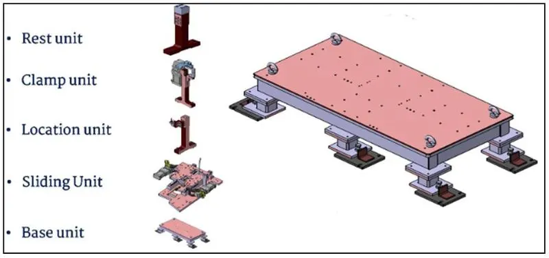
- Fixed pin Units: -
Fixed pins are used to hold the panels firmly in a fixture assembly, to prevent the car panels from dislocation and mis-alignment on the resting members of the fixture.
Fixed pins assures that the panels are fixed while performing operation on it, without any motion in form of horizontal / vertical sliding from its original position.
Q.12)
FIXED PIN UNIT
A pin unit in which pin’s position is fix, is called Fixed Pin Unit.
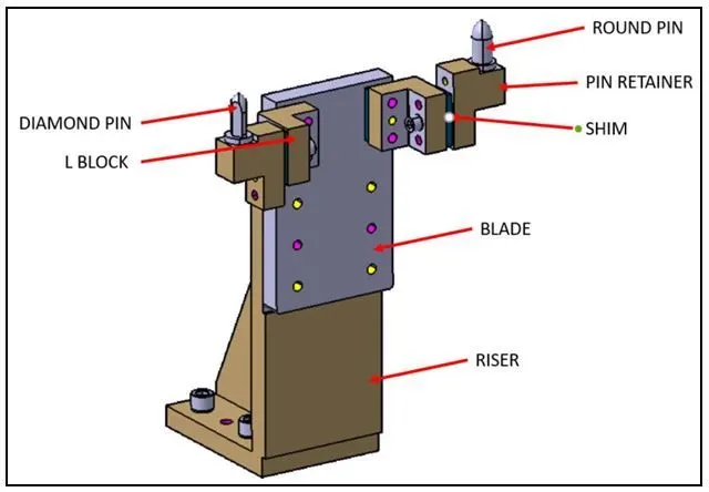
Pin unit is used to lock the rotational position of panel. Round Pin is used to control panel in two directions while Diamond Pin is used to control panel in one direction.
Application of fixed pin unit
The fixed pin unit is the part of the 3-2-1 principle. It restricts 6 degrees of freedom of the car panel.
It is necessary to have 2 pins to locate car panel. one pin must arrest 4 way (4 translational motion) & other must arrest 2 way (2 rotational motion) of a car panel.
Q.13)
DIFFERENT PARTS OF A FIXED UNIT
The Different parts of a Fixed Unit are shown below: -
1.) Pin.
2.) Pin retainer.
3.) Shims.
4.) Blade.
5.) Riser.
PIN
Pin is used to locate the panel in fixture assembly.
Typically, the locating pins are used to locate a body part in a position sufficiently accurate to execute a typical process / operation.
The body part is constrained by a set of appropriately locating pin, which restricts the motion of the panel from its original position.
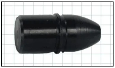
Few different types of pins are shown below,
- Bullet-nose dowels have a long, tapered nose. They are similar to bullet-nose pins, explained below, but have a smaller locating shoulder. They are almost always used with a bushing.
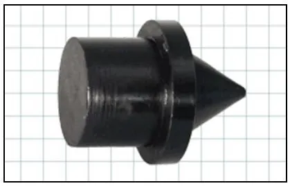
- Cone locator pinscan compensate for a moderate amount of misalignment. They are similar to round or diamond locating pins, but have cone-shaped tips.
- Diamond locating pinshave four flat, diamond-shaped edges on the head. They are often used with a round pin to provide multi-axis alignment.
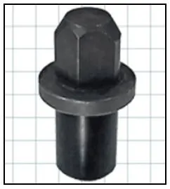
PIN RETAINER
A pin retainer is a part which holds the pin firmly. The pin retainer can either be custom made or of standard make to suit the pin.
Pin retainer prevents pin from shifting to its position, thus making the panel to restrict from motion.
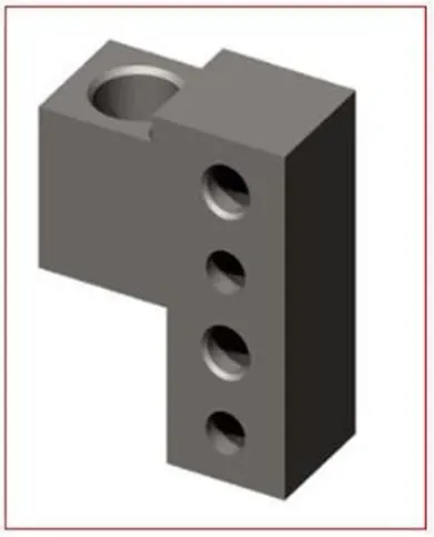
SHIMS
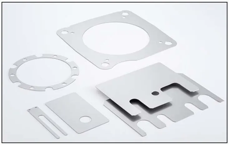
Shims are used in fixture construction for filling gaps and to compensate for manufacturing tolerances.
They are mainly used for adjusting the clamping points on tools or fixtures e.g. in the automotive or aerospace industry. A clamping point is used to fix one or more components.
The usually rectangular shape and one to three slotted holes allow you to replace the shims at the clamping points without having to turn the screws completely out of the fixture. Loosening the screws is sufficient here to remove sheets or to attach others.
BLADE
Blade are the supportive plate attached to the riser of the fixture.
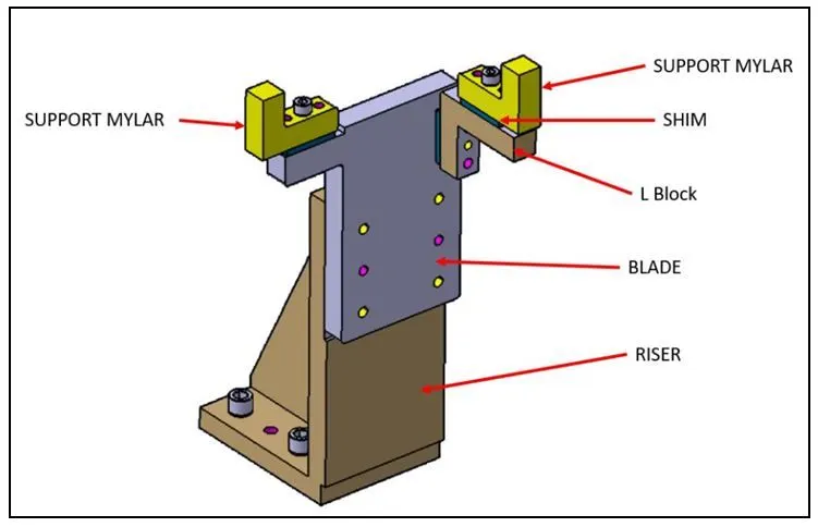
The Blade supports the components like – L-block, Mylars, Mounting for Pneumatic Cylinders and other tooling attachment as per the requirement.
RISER
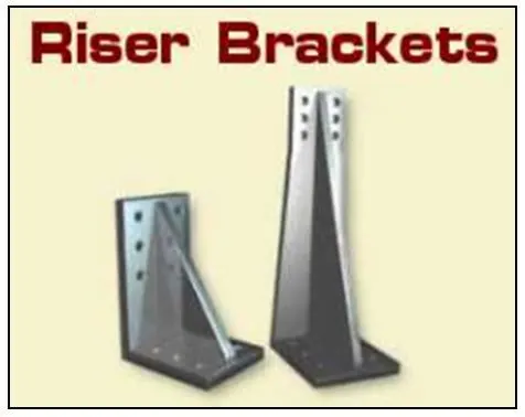
Risers are the vertical members of the fixture assembly, which holds the respective tools to perform the operation on the panels.
Q.14)
PURPOSE OF REST UNIT & ITS PARTS
Rest Unit
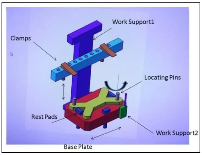
Rest unit is designed to support the car panel using Mylar/ NC block.
The panel just sits on the area of rest blocks / pads, without any application of clamping force.
The parts of rest unit are as follows,
- NC block/mylars.
- Risers.
- Blades.
- shims.
NC BLOCK / MYLARS
MYLAR is one kind of block that touches the panel and holds or clamps the panel.
Mylars are always designed in CAR LINE. Mylar is also called NC (Numerically Controlled) Block. Mylars are mounted on any block or plate with Shimming, so that height of mylar can be adjusted accordingly at the assembly level.
For ‘A’ class surfaces Nylon mylars are used. So that surface can be saved from scratches.
RISER
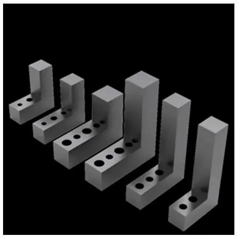
The part which is mounted on the base plate and holds a clamp or pin cylinder on it, is called Riser.
Riser can be Standard Part or manufactured part, it varies from project to project.
A riser can be a Single part or welded part. Standard risers also have various shapes and sizes.
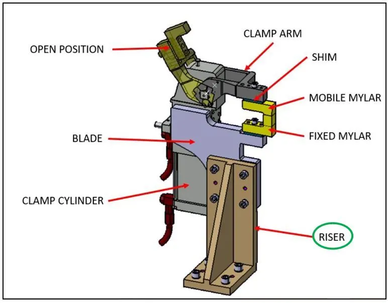
The Riser is shown in the above diagram by oval circle in green color.
BLADES
The plate which connects Riser to the Clamp cylinder is named as Blade.
This plate plays an important role in building the unit. The plate can be of any shape. But we need to keep in mind that the plate should be as compact as possible.
SHIMS
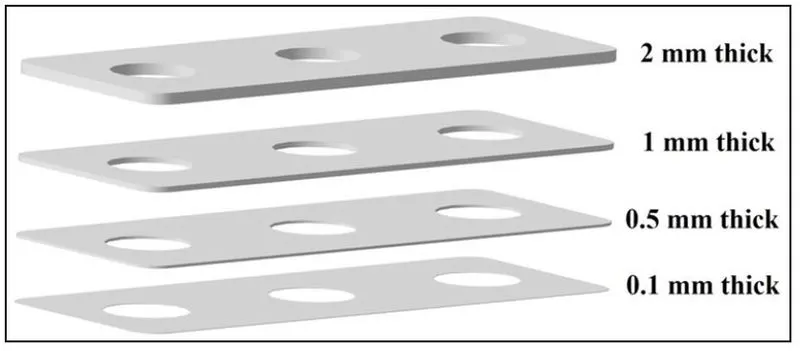
Shim is a set of thin plates (2 mm, 1mm, 0.5 mm, 0.25mm) that are used to adjust the gap or used for a better fit. Shimming can be of thickness 5mm, 8mm, or 10mm. in case no proper fitting between mylar and Panel due to manufacturing errors then this error can be removed using shims. Shims are placed in the carline position so that gap can be adjusted in the required direction like X, Y, or Z.
There are three types of shimming. These are one-way, two-way, and three-way shimming.
Number of shimming depends upon the NC cut angle and PIN angle with the car line.
- If NC cut is less than 15 deg. then mylar will have one-way shimming.
- If NC cut is more than 15 deg. in one direction then mylar will have a 2-way direction shimming
- If NC has more than 15 deg. angle in two directions then mylar will have 3-way directional shimming.
Q.15)
BASIC FUNDAMENTALS TO DESIGN A SENSOR UNIT
A sensor unit is a unit designed to sense the car panel by using electrical sensors.
This signals from the sensors will be fed to the PLC and so the next process will be executed by the signal.
Fundamentals to Design a Sensor Unit:
Every single loose panel which are being welded in a tool should be sensed.
Each panel should be sensed by 1 or 2 sensors depend on the size of the panel, preferred to be in diagonal opposite ends of panel.
Every sensor should be mounted in a 3-direction adjustable way in general.
The major types of Sensors are: -
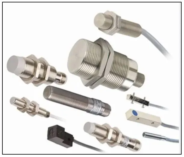
- Proximity Sensor
Proximity sensors are one of the most common ways to incorporate sensing into weld fixtures. These sensors can be used in a variety of applications including part presence, poka-yoke, or even position verification.
Proximity sensors are categorized two ways – normally open or normally closed. Another way to think about this is the sensor verifying something is either present or not present. Both applications are used in weld fixtures. Other proximity sensors including capacitive proximity sensors, photoelectric sensors, and inductive proximity sensors. The materials and applications determine the type of sensor required. Proximity sensors also have a variety of field or beam specifications.
- Photoelectric Sensor
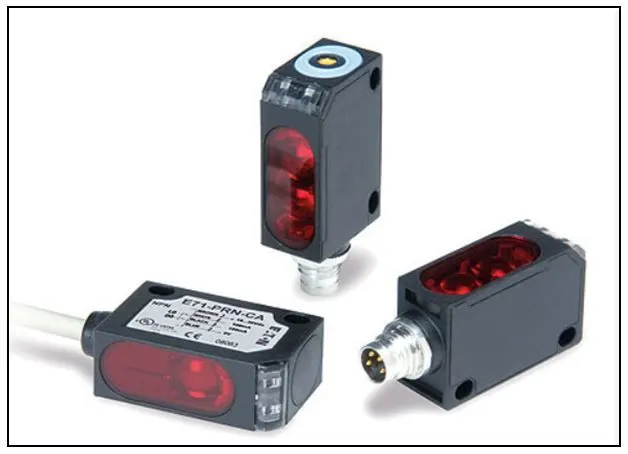
A photoelectric sensor is an optical sensor which consists of a light source, light receiver and a signal processing and control output circuitry. They can detect the presence of objects and sometimes even the surface conditions as well.
When the emitted light is interrupted by an object in close proximity, the light receiver detects this change and turns the output of the sensor on or off. Some proximity sensors are even able to determine the distance to the object as well.
- Laser Sensor
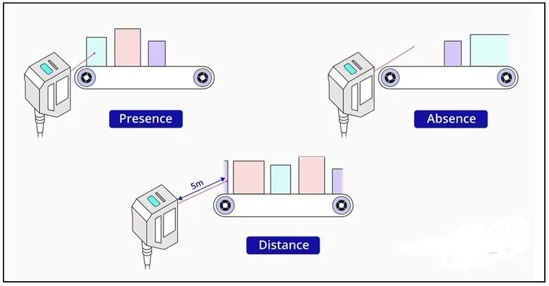
A laser sensor is an electric device that uses a focused light beam to detect the presence, absence, or distance of an object.
The light that a laser sensor emits is a small bright dot, similar to a laser pointer. This dot is bright enough to be easily seen even in direct sunlight. And being able to see this dot easily, makes it easier to set up and troubleshoot the laser sensor.
Q.16)
ROUGH LOCATOR UNIT & ITS BASIC FUNDAMENTALS FOR CONSIDERATION DURING DESIGN
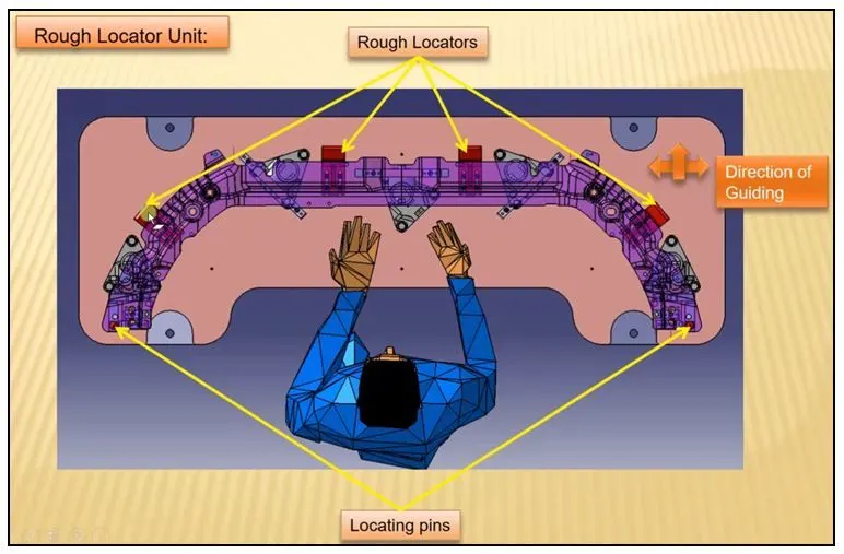
Rough locator unit is a unit designed to guide the operator to locate the car panel on the to the pins accordingly.
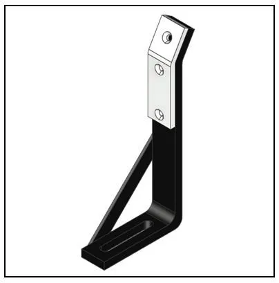
A rough locator can be standard part or make part.
The basic fundamentals to consider while designing a rough locator
- Rough locator should be placed at the edges of the car panel, which has to guide.
- Rough locator should be placed in the same angle of the car part edge with a minimum distance of 2 – 5 mm from the edge of car part.
- Rough locators should guide the panels in a pin assemble direction in general.
- Rough locators should start guiding the panel before 10 to 15mm to the start of the pin engagement.
- Rough locators should be designed with entry angle for car part entry.
- Rough locators should be designed with two slots to mount for easy adjustment in general.
- The slots should be in the direction of car part guiding.
Q.17)
BASE UNIT AND IT'S PARTS
A base unit is the unit designed to mount all the other units (Clamp unit, Pin unit, rest unit etc.) of the tool, also other parts necessary for a tool like pneumatic valve box, trunking cable path will also be mounted on to a base unit.
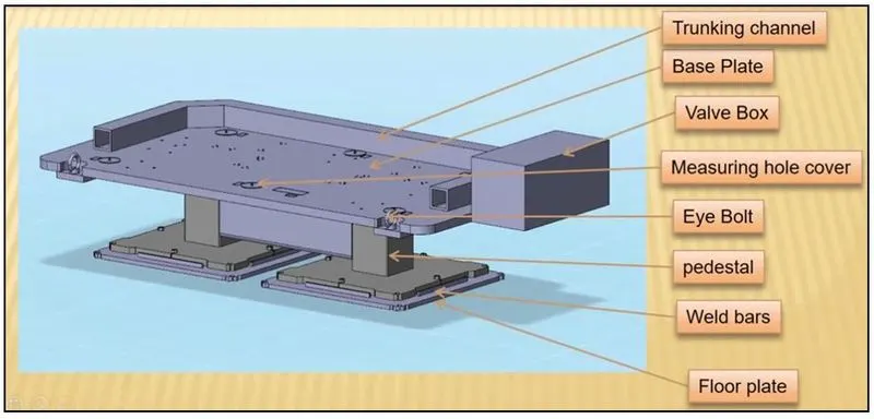
The Base Unit holds the Risers, which supports the clamp unit and the respective tools.
The Parts of the Base unit are: -
- Trunking Channel.
The Trunking Channel holds all the necessary cable harness bundles of the pneumatic actuator and electricity supply to the tools to perform operations.
- Base Plate.
Base plate is the place, where there are mounting holes provided to firmly hold the Risers.
- Valve Box.
Valve box is basically a box which supplies air to all the pneumatic cylinders assembled in the fixture.
- Measuring Hole Cover
The Measuring hole cover are the specific points in the base plate, where the co-ordinates of the UNITS are present.
- Eye Bolt.
Eye Bolt is provided to lift the base unit, for shifting from one location to another location.
Pedestal are the vertical columns, which carries the load of the Base plate.
- Weld Bars.
Weld Bars are the welded sections which is made between the pedestal resting plate and the floor plate.
- Floor plate.
Floor Plate is the one which rests on the ground, carrying the overall load of pedestal, base unit and the other related units.
Q.18)
DUMP UNIT AND ITS FUNCTIONS
Dump unit is found in complex fixture.
Dump unit is used when there is any geometrical constraints while placing a panel.
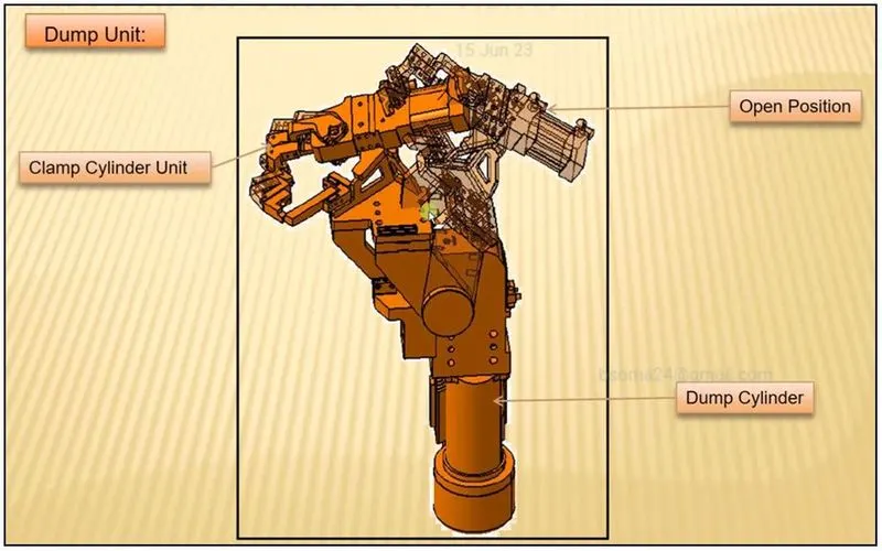
The first cylinder dumps the assembly carrying clamp mylars, pins and performs the required operation.
When the specified task is completed, we should make sure that during the open position of clamp cylinder unit, we should be able to remove the panel.
The above figure shows the open position of the clamp cylinder unit, which is done by the Dump cylinder.
Q.19)
SLIDE UNIT
Slide unit is used to shift a particular section of fixture assembly by the mechanism of guide and rail.
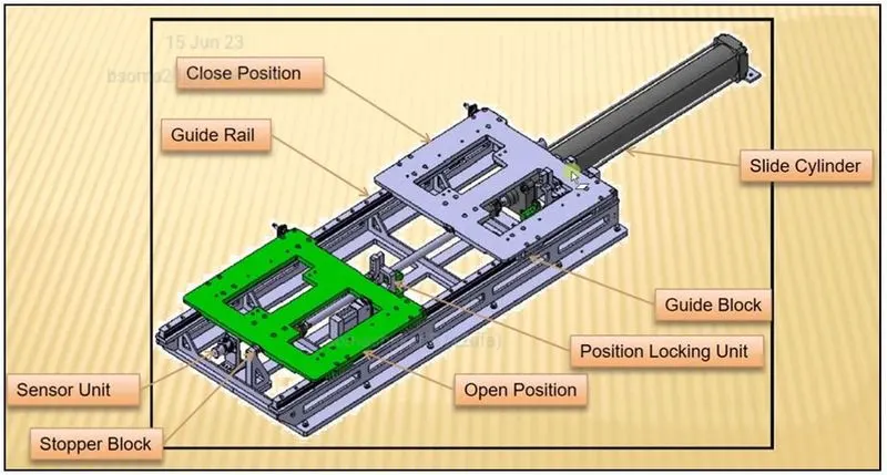
The parts of the slide units are: -
- Guide Rail
Guide rail is to guide the block, which holds the specific unit to perform the operation on the panel. Based on the required distance, the Guide rail is designed to serve its function of sliding the unit assembly.
- Guide Block
Guide Block has bearing arrangement or set of wheels present adjacent to each other on either ends of the Base plate.
- Slide Cylinder
The Guide Block slides on the Guide Rail by the help of pneumatic cylinder. Based on the selected length of the guide rail, the stroke length of the cylinder is calculated.
- Stopper Block
Stopper Block is used to stop the Guide Block from further sliding. The Stopper block is the ending point, beyond which the sliding motion is restricted.
- Sensor unit
Sensor units sends the signal to the control system of the pneumatic cylinder arrangement to stop the further movement of piston from the bore of the cylinder, thus stopping the sliding of guide block on guide rail.