Week 3:- BiW Fixture Design Methodologies Challenges
1. What is Design methodology?
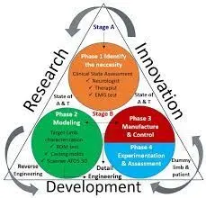
Design methods are procedures, techniques, aids, or tools for designing. They offer a number of different kinds of activities that a designer might use within an overall design process. Conventional procedures of design, such as drawing, can be regarded as design methods, but since the 1950s new procedures have been developed that are more usually grouped together under the name of "design methods". What design methods have in common is that they "are attempts to make public the hitherto private thinking of designers; to externalise the design process". Design methodology is the broader study of method in design: the study of the principles, practices and procedures of designing.
2. What are the inputs required from the customer to start designing a Fixture?
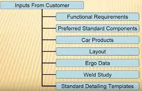
First understand scope of the work. Means what is expected by customer. Every customer has its specific requirements and it may have own raw material, electric, pneumatic,cad, design standards.Every customer also gives different inputs and expects output e.g 2d drawing, process sheet in xls, pdf, CAD format of design, layout format, OLP.
- Bill of material (BOM) of the components to be welded- spot welding
- CAD panel data or at least 2D drawing of assembly and individual panel data
- Sheet metal panel thickness.Plays major role to decide 2 metal or 3 metal weld.
- Spot Detail information like total no of spots and spacing between the spots.
- Weld information clarity from drawing like 2 metal or 3 metal welding
- PLP (Principle location scheme) of the individual panel and total assembly.
- Cycle time - if calculated or can be found out as per manual or robotic welding process.
- Process sheet if Process engineering is done - where loading sequence, no of clamp data and gun data is mentioned.
- All clamping cylinder and fixtures standards.
- CAD -Software guidelines
- Raw material standards
- Design guidelines
- Bought out item(Purchased parts) standards like pneumatic items, toggle clamp, bearing, screw, dowel etc company information
3. What is the input we get from "Car Products"?
Geometric dimensioning and tolerance (GD&T) - GD&T will be given of the part for which we need to design the fixture . it will provide information about locating pin , sequence of opening of clamps , rest , dump and slide stroke information .
- Parts list - Part list will give us detailed information about the parts involved in the fixture . it will give us information like part name , part number , thickness of part , quantity of parts etc .
- Cad files - Cad files of the part gives us information of 3d model , design analysis result . this information is very uselful as it will give us an idea on starting to design a fixture .
- Clamp plan - Clamp plan is very important information as it will give us idea of places where we have our clamps , pins , dumps , rest etc . we should never change the clamp position unless we ask the customer and they agree to it .
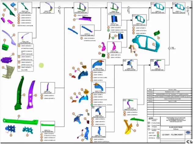
- Product assembly process sheets - In product asssembly process sheet , we will find what kind of products we are going to assemble for the particular unit or the component . The sequence of the assembly will also be given in this sheet .
4. What is the Clamp plan?
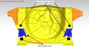
Clamps are versatile tools that serve to temporarily hold work securely in place. They are used for many applications including carpentry, woodworking, furniture making, welding, construction and metal working. A clamp is a fastening device used to hold or secure objects tightly together to prevent movement or separation through the application of inward pressure.
5. What is the purpose of a Layout?
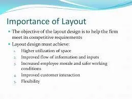
Layout is the design and arrangement of the text, images, and other content on a web page. It can be thought of as the foundation of a website, and it is essential for a website to look professional and inviting. A well-designed layout will help to create a positive first impression, and it can encourage visitors to stay on your website longer. Layout is also important for SEO purposes. The layout of a website can influence how search engines rank your site. For example, a layout that is well organized and easy to navigate will rank higher than a site that is cluttered or difficult to use. In addition, good layout can also help to improve the overall readability of your content.There are many different layout design tools available online, and it is important to choose the one that is best suited for your needs. Some of the most popular include Adobe Photoshop, Inkscape, and Sketch.
6. What is Ergo data?
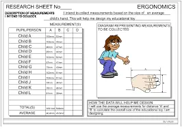
ERGO integrates proprietary data within the biological knowledge network allowing access to this larger biological context to assess significance, support graph diffusion analytics and enrichment analyses, and better interpret results.
7. What do you understand by Weld study?
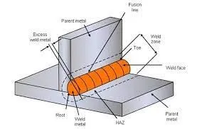
Welding is a fabrication process whereby two or more parts are fused together by means of heat, pressure or both forming a join as the parts cool. Welding is usually used on metals and thermoplastics but can also be used on wood. The completed welded joint may be referred to as a weldment. Welders provide necessary services to various industries, including manufacturing, transportation and infrastructure. Working in a high-demand field can be beneficial, as it guarantees stable employment and higher wages because the skills of the trade are highly valuable to employers. In addition to melting the base metal, a filler material is typically added to the joint to form a pool of molten material (the weld pool) that cools to form a joint that, based on weld configuration (butt, full penetration, fillet, etc.), can be stronger than the base material. Pressure may also be used in conjunction with heat or by itself to produce a weld. Welding also requires a form of shield to protect the filler metals or melted metals from being contaminated or oxidized. Many different energy sources can be used for welding, including a gas flame (chemical), an electric arc (electrical), a laser, an electron beam, friction, and ultrasound. While often an industrial process, welding may be performed in many different environments, including in open air, under water, and in outer space. Welding is a hazardous undertaking and precautions are required to avoid burns, electric shock, vision damage, inhalation of poisonous gases and fumes, and exposure to intense ultraviolet radiation. Until the end of the 19th century, the only welding process was forge welding, which blacksmiths had used for millennia to join iron and steel by heating and hammering. Arc welding and oxy-fuel welding were among the first processes to develop late in the century, and electric resistance welding followed soon after. Welding technology advanced quickly during the early 20th century as world wars drove the demand for reliable and inexpensive joining methods. Following the wars, several modern welding techniques were developed, including manual methods like shielded metal arc welding, now one of the most popular welding methods, as well as semi-automatic and automatic processes such as gas metal arc welding, submerged arc welding, flux-cored arc welding and electroslag welding. Developments continued with the invention of laser beam welding, electron beam welding, magnetic pulse welding, and friction stir welding in the latter half of the century. Today, as the science continues to advance, robot welding is commonplace in industrial settings, and researchers continue to develop new welding methods and gain greater understanding of weld quality.
8. What are the criteria for percentage completion in the designing stage? Explain it in detail

The percentage of completion method is an accounting method in which the revenues and expenses of long-term contracts are recognized as a percentage of the work completed during the period. This is in contrast to the completed contract method, which defers the reporting of income and expenses until a project is completed. The percentage-of-completion method of accounting is common for the construction industry, but companies in other sectors also use the method.
- The percentage of completion method reports revenues and expenses in terms of the work completed to date.
- This method can only be used if payment is assured and estimating completion is relatively straightforward.
- The percentage of completion method has been misused by some companies to boost short-term results.
Understanding the Percentage of Completion Method
The percentage of completion method of accounting requires the reporting of revenues and expenses on a period-by-period basis, as determined by the percentage of the contract that has been fulfilled. The current income and expenses are compared with the total estimated costs to determine the tax liability for the year. For example, a project that is 20% complete in year one and 35% complete in year two would only have the incremental 15% of the revenue recognized in the second year. The recognition of income and expenses on this work-in-progress basis applies to the income statement, but the balance sheet is handled the same way as the completed contract method.
Examples of the Percentage of Completion Method
The percentage of completion accounting method is commonly used by construction firms that are contractors for buildings, energy facilities, public sector infrastructure, and other long-term physical projects. It has also been used by defense contractors (think nuclear submarines or aircraft carriers) and software developers whose projects represent a multi-year commitment of resources. For software developers, the product must be a significant custom-designed project for a client.

A design output is a drawing or specification or manufacturing instruction. Design outputs describe all the components, parts, and pieces that go into your medical device. Design outputs describe all assemblies and subassemblies of your product.
Think of it like this. If you were tasked with assembling a medical device from scratch, what documentation would you need to do so? All this documentation that you would need--design outputs.
Design outputs established during product development become the basis of the device master record (DMR) when in production.
DEVICE MASTER RECORD AND DESIGN OUTPUTS
Your DMR is essentially the “recipe” for your device. It contains all the ingredients that you or a third-party would need to manufacture and test the device. Sometimes, there is confusion between outputs and the DMR, but this is easily cleared up. Not all design outputs will be included in your DMR.
As per FDA 21 CFR Part 820.181:
Each manufacturer shall maintain device master records (DMR's). Each manufacturer shall ensure that each DMR is prepared and approved in accordance with 820.40.
As such, the DMR is an example of a required Design output. The two are, of course, very closely connected. The information in your DMR will be used to evaluate your device during the design verification stage.
"Adequate Evaluation" of Design Outputs?
Design outputs must contain and/or make reference to "acceptance criteria". Think of acceptance criteria as a tolerance of sorts. In order to adequately evaluate design outputs, design verification is necessary. And this evaluation is comparing design outputs against design inputs.
Tests are NOT design outputs.
Establishing solid, objective design inputs is the key. Good design inputs make it easier to create design outputs.
And by always keeping design verification (how you prove it) in mind during design inputs and design outputs, these important medical device product development tasks become a lot smoother.
FINAL THOUGHTS
Hopefully this guide has shown you the importance of design inputs and design outputs. Taking the time to craft solid design inputs will feed into the performance and success of your entire project. Your design outputs, on the other hand, are crucial for a successful design transfer, and for testing and verifying your device.
Greenlight Guru’s medical device QMS solution was specifically designed to allow for clear, traceable documentation of design inputs and design outputs. Our MDQMS is also aligned to the best practices in risk management and change management for the medical device industry. You can click here to take a quick tour of our medical device QMS software.
10. What do you understand by structuring a design tree? How does it reduce errors during the design process?
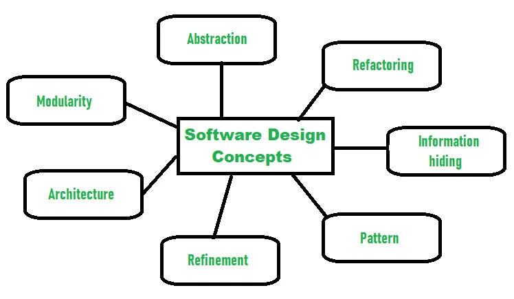
- Abstraction- hide Irrelevant data
Abstraction simply means to hide the details to reduce complexity and increases efficiency or quality. Different levels of Abstraction are necessary and must be applied at each stage of the design process so that any error that is present can be removed to increase the efficiency of the software solution and to refine the software solution. The solution should be described in broad ways that cover a wide range of different things at a higher level of abstraction and a more detailed description of a solution of software should be given at the lower level of abstraction. - Modularity- subdivide the system
Modularity simply means dividing the system or project into smaller parts to reduce the complexity of the system or project. In the same way, modularity in design means subdividing a system into smaller parts so that these parts can be created independently and then use these parts in different systems to perform different functions. It is necessary to divide the software into components known as modules because nowadays there are different software available like Monolithic software that is hard to grasp for software engineers. So, modularity in design has now become a trend and is also important. If the system contains fewer components then it would mean the system is complex which requires a lot of effort (cost) but if we are able to divide the system into components then the cost would be small. - Architecture- design a structure of something
Architecture simply means a technique to design a structure of something. Architecture in designing software is a concept that focuses on various elements and the data of the structure. These components interact with each other and use the data of the structure in architecture. - Refinement- removes impurities
Refinement simply means to refine something to remove any impurities if present and increase the quality. The refinement concept of software design is actually a process of developing or presenting the software or system in a detailed manner that means to elaborate a system or software. Refinement is very necessary to find out any error if present and then to reduce it. - Pattern- a repeated form
The pattern simply means a repeated form or design in which the same shape is repeated several times to form a pattern. The pattern in the design process means the repetition of a solution to a common recurring problem within a certain context. - Information Hiding- hide the information
Information hiding simply means to hide the information so that it cannot be accessed by an unwanted party. In software design, information hiding is achieved by designing the modules in a manner that the information gathered or contained in one module is hidden and can’t be accessed by any other modules. - Refactoring- reconstruct something
Refactoring simply means reconstructing something in such a way that it does not affect the behavior of any other features. Refactoring in software design means reconstructing the design to reduce complexity and simplify it without affecting the behavior or its functions. Fowler has defined refactoring as “the process of changing a software system in a way that it won’t affect the behavior of the design and improves the internal structure”.
Different levels of Software Design:
There are three different levels of software design. They are:
- Architectural Design:
The architecture of a system can be viewed as the overall structure of the system & the way in which structure provides conceptual integrity of the system. The architectural design identifies the software as a system with many components interacting with each other. At this level, the designers get the idea of the proposed solution domain.
- Preliminary or high-level design:
Here the problem is decomposed into a set of modules, the control relationship among various modules identified, and also the interfaces among various modules are identified. The outcome of this stage is called the program architecture. Design representation techniques used in this stage are structure chart and UML.
- Detailed design:
Once the high-level design is complete, a detailed design is undertaken. In detailed design, each module is examined carefully to design the data structure and algorithms. The stage outcome is documented in the form of a module specification document.
11. What are Units? Mention 5 types of units
A base unit is a unit adopted for measurement of a base quantity. A base quantity is one of a conventionally chosen subset of physical quantities, where no quantity in the subset can be expressed in terms of the others.
Pins are sized by their length; each digit equals 1/16 inch, so a size 20 pin is 20/16 inch or 1 1/4 inches long.
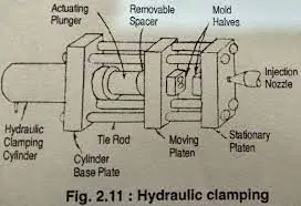
The clamping units are used to keep the mold shut against the forces developed when injection pressure pushes plastic into the closed mold. Therefore, the amount of clamp force must be at least equal to the amount of injection force. The machine sizes are determined by the clamping tonnage forces.
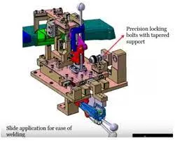
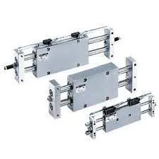
Slide units are used at places where there are space constraints and places where there is less accessibility. Sometimes, there are too many small panels near each other and there is not enough space as each panel requires resting, location using 2 pins, clamping and sensing.
12. Describe Fixed Pin units & their purpose?
Fix Pin Unit
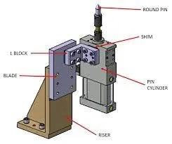
An assembly of standard and manufacturing parts consisting location pin is called Pin unit. A pin unit in which pin’s position is fix, is called Fixed Pin Unit. Pin unit is used to lock the rotational position of panel. Round Pin is used to control panel in two directions while Diamond Pin is used to control panel in one direction.
Inline Retractable Pin Unit
Inline Retractable Pin unit consist one Pin cylinder which operates the pin in one direction. In this unit Pin is directly mounted on the cylinder and it is must to have pin and cylinder inline with the hole or slot of the panel. Pin cylinder is controlled in two directions with the help of shimming. Below picture is an example of inline retractable pin cylinder.
Pin cylinders have various stroke sizes like 30mm,40mm,60mm. Cylinder. Uses of cylinder depends upon the area and available while building the fixture.
Offset Retractable Pin Unit
Offset Retractable Pin unit consist one Pin cylinder which operates the pin in one direction. In this unit Pin is mounted on the Pin retainer and then pin is controlled in two directions with the help of shimming . In this unit cylinder can be mounted away from the pin.
These Pin cylinders have various stroke sizes like 30mm,40mm,60mm. Cylinder. Uses of cylinder depends upon the area and available while building the fixture.
Whether we should go for inline cylinder or offset cylinder, depends upon the requirement and space available in the tool. Below Given Pic is the example of Offset Retractable Pin Unit.
Fixed pin is a unit designed to locate the car using pin. As the name suggest it uses a fixed pin which cannot be moved by any distance. The top most part is the fixed pin which will be used to locate the part. The part will have entry hole in which the pin will enter to arrest the motion of the part.
13. What are the different parts of a fixed unit?
Fix Pin Unit
An assembly of standard and manufacturing parts consisting location pin is called Pin unit. A pin unit in which pin’s position is fix, is called Fixed Pin Unit. Pin unit is used to lock the rotational position of panel. Round Pin is used to control panel in two directions while Diamond Pin is used to control panel in one direction.
Inline Retractable Pin Unit
Inline Retractable Pin unit consist one Pin cylinder which operates the pin in one direction. In this unit Pin is directly mounted on the cylinder and it is must to have pin and cylinder inline with the hole or slot of the panel. Pin cylinder is controlled in two directions with the help of shimming. Below picture is an example of inline retractable pin cylinder.
Pin cylinders have various stroke sizes like 30mm,40mm,60mm. Cylinder. Uses of cylinder depends upon the area and available while building the fixture.
Offset Retractable Pin Unit
Offset Retractable Pin unit consist one Pin cylinder which operates the pin in one direction. In this unit Pin is mounted on the Pin retainer and then pin is controlled in two directions with the help of shimming . In this unit cylinder can be mounted away from the pin.
These Pin cylinders have various stroke sizes like 30mm,40mm,60mm. Cylinder. Uses of cylinder depends upon the area and available while building the fixture.
Whether we should go for inline cylinder or offset cylinder, depends upon the requirement and space available in the tool. Below Given Pic is the example of Offset Retractable Pin Unit.
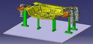
Rest unit is unit designed to support car panel using Mylar/ NC block/ rest component is rested only, no upper clamp or force applied there. It is the simplest unit to design because it has fewer parts to design & the purpose is only resting of the car panel. Because of the simplicity the rest unit is combined with other unit to reduce the cost of the overall project.It can be combined with clamp unit to clamp as well as to rest the car panel. It can be combined with locating unit to locate as well as to rest the car panel. Also locating, clamping & Test unit can be combined together in one unit to reduce cost.There is no cylinder attached to it. It has rest Mylar, blade and riser & below is different parts of rest unit. Rest unit is also divided into simple support unit, multiple support units & retractable support unit.These units are used to rest the panel. Take an overview of the working height if you’re having manual welding. For robotic welding also it’s important to see the working height in consideration of the robotic gun, turn table height if manual loading is done. Put the proper gun at the spot location for all the spots near the rest unit. If process engineer has gun shape stick to X, C or Y type of gun. Do the proper gun study and place the gun as per the GEO or re-spot decision and operator approach. Once basic gun is placed considering the throat depth and throat gap start building the clamp and rest block at the PLP.
15. What are the basic fundamentals to design a Sensor unit?
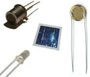
A sensor is a device that produces an output signal for the purpose of sensing a physical phenomenon. In the broadest definition, a sensor is a device, module, machine, or subsystem that detects events or changes in its environment and sends the information to other electronics, frequently a computer processor. Sensors are always used with other electronics.Sensors are used in everyday objects such as touch-sensitive elevator buttons (tactile sensor) and lamps which dim or brighten by touching the base, and in innumerable applications of which most people are never aware. With advances in micromachinery and easy-to-use microcontroller platforms, the uses of sensors have expanded beyond the traditional fields of temperature, pressure and flow measurement, for example into MARG sensors. Analog sensors such as potentiometers and force-sensing resistors are still widely used. Their applications include manufacturing and machinery, airplanes and aerospace, cars, medicine, robotics and many other aspects of our day-to-day life. There is a wide range of other sensors that measure chemical and physical properties of materials, including optical sensors for refractive index measurement, vibrational sensors for fluid viscosity measurement, and electro-chemical sensors for monitoring pH of fluids. A sensor's sensitivity indicates how much its output changes when the input quantity it measures changes. For instance, if the mercury in a thermometer moves 1 cm when the temperature changes by 1 °C, its sensitivity is 1 cm/°C (it is basically the slope dy/dx assuming a linear characteristic). Some sensors can also affect what they measure; for instance, a room temperature thermometer inserted into a hot cup of liquid cools the liquid while the liquid heats the thermometer. Sensors are usually designed to have a small effect on what is measured; making the sensor smaller often improves this and may introduce other advantages. Technological progress allows more and more sensors to be manufactured on a microscopic scale as microsensors using MEMS technology. In most cases, a microsensor reaches a significantly faster measurement time and higher sensitivity compared with macroscopic approaches. Due to the increasing demand for rapid, affordable and reliable information in today's world, disposable sensors—low-cost and easy‐to‐use devices for short‐term monitoring or single‐shot measurements—have recently gained growing importance. Using this class of sensors, critical analytical information can be obtained by anyone, anywhere and at any time, without the need for recalibration and worrying about contamination.
16. What is a Rough locator unit & what are the basic fundamentals to consider while designing it?
Rough locators are used to help locate workpieces in the automation process. Locating refers to the desired location where you want the workpiece to be when it is getting worked on either by a person, team, or robot.It is a device to establish and maintain position of a part in a jig or fixture.
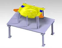
Rough locators are used to help locate workpieces in the automation process. Locating refers to the desired location where you want the workpiece to be when it is getting worked on either by a person, team, or robot. The accuracy of the locating components directly affects the consistency and how the final product will come out. This is why we make all of our rough locators in-house because we understand that these components are essential to your setup. We are ISO 9001:2015 certified so from start to finish you can expect that our rough locators will do their job right. We offer all NAAMS catalog codes, both current and discontinued.
ARL-Series
NAAMS rough locators in the ARL series include both L-shaped and I-shaped locators offering hardening UHMW guide options. They feature a 35mm bend at 60° with a height from bend ranging from 65mm to 320mm. The width of these locators are 19mm, 32mm or 50.8mm for UHMW guides and all come with single slot design. All hardened rough locators end with an H suffix, which is hardened to 58-62 HRC, 1.0-1.5mm deep.
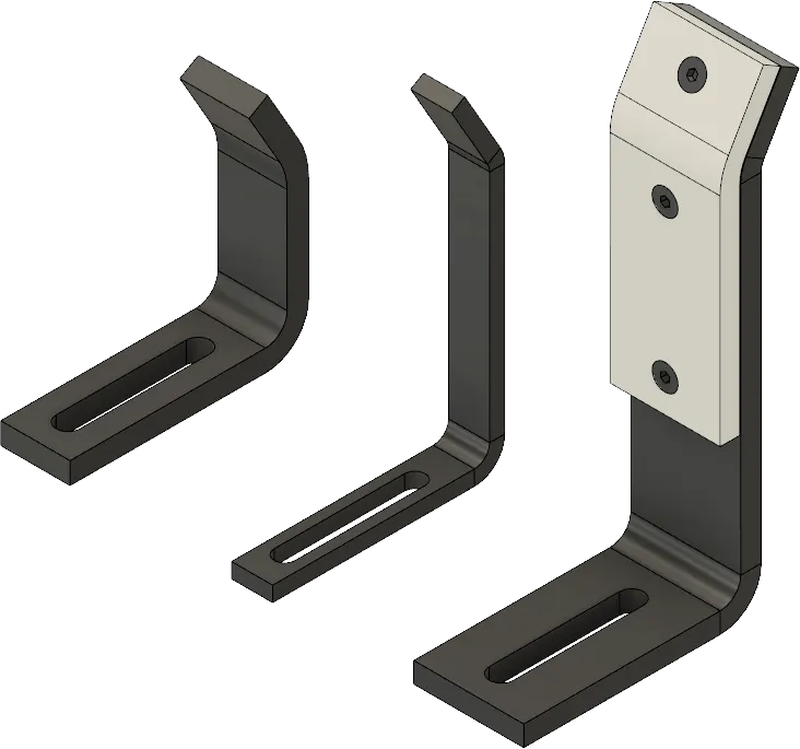
L-Shaped Rough Locators
NAAMS rough locators L-shape have either an inside bend or outside bend. The base is 100mm before the vertical bend and height are dependent on the specific NAAMS code. All bends are 35mm long with a 30° bend. Look below for the desired height before the bend below with the appropriate code.
| L-Shaped Rough Locators | |||||
|---|---|---|---|---|---|
| NAAMS Code | Height before bend | Weight (kg) | NAAMS Code | Height before bend | Weight (kg) |
| (A) mm | (A) mm | ||||
| ARL075L | 75 | 0.45 | ARL075R | 65 | 0.42 |
| ARL075LH | 0.45 | ARL075RH | 0.42 | ||
| ARL075LP | 0.78 | ARL075RP | 0.74 | ||
| ARL076L | 0.17 | ARL076R | 0.16 | ||
| ARL076LH | 0.17 | ARL076RH | 0.16 | ||
| ARL100L | 100 | 0.51 | ARL100R | 90 | 0.48 |
| ARL100LH | 0.51 | ARL100RH | 0.48 | ||
| ARL100LP | 0.87 | ARL100RP | 0.83 | ||
| ARL101L | 0.19 | ARL101R | 0.18 | ||
| ARL101LH | 0.19 | ARL101RH | 0.18 | ||
| ARL125L | 125 | 0.57 | ARL125R | 115 | 0.54 |
| ARL125LH | 0.57 | ARL125RH | 0.54 | ||
| ARL125LP | 0.97 | ARL125RP | 0.93 | ||
| ARL126L | 0.21 | ARL126R | 0.2 | ||
| ARL126LH | 0.21 | ARL126RH | 0.2 | ||
| ARL150L | 150 | 0.62 | ARL150R | 140 | 0.6 |
| ARL150LH | 0.62 | ARL150RH | 0.6 | ||
| ARL150LP | 1.1 | ARL150RP | 1 | ||
| ARL151L | 0.23 | ARL151R | 0.22 | ||
| ARL151LH | 0.23 | ARL151RH | 0.22 | ||
| ARL175L | 175 | 0.68 | ARL175R | 165 | 0.66 |
| ARL175LH | 0.68 | ARL175RH | 0.66 | ||
| ARL175LP | 1.2 | ARL175RP | 1.1 | ||
| ARL176L | 0.26 | ARL176R | 0.24 | ||
| ARL176LH | 0.26 | ARL176RH | 0.24 | ||
| ARL200L | 200 | 0.74 | ARL200R | 190 | 0.72 |
| ARL200LH | 0.74 | ARL200RH | 0.72 | ||
| ARL200LP | 1.3 | ARL200RP | 1.2 | ||
| ARL201L | 0.28 | ARL201R | 0.27 | ||
| ARL201LH | 0.28 | ARL201RH | 0.27 | ||
| ARL225L | 225 | 0.8 | ARL225R | 215 | 0.78 |
| ARL225LH | 0.8 | ARL225RH | 0.78 | ||
| ARL225LP | 1.4 | ARL225RP | 1.3 | ||
| ARL226L | 0.3 | ARL226R | 0.29 | ||
| ARL226LH | 0.3 | ARL226RH | 0.29 | ||
| ARL250L | 250 | 0.86 | ARL250R | 245 | 0.84 |
| ARL250LH | 0.86 | ARL250RH | 0.84 | ||
| ARL250LP | 1.5 | ARL250RP | 1.4 | ||
| ARL251L | 0.32 | ARL251RH | 0.31 | ||
| ARL251LH | 0.32 | ARL251R | 0.31 | ||
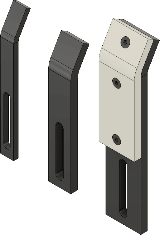
I-Shaped Rough Locators
NAAMS rough locators I-shape is straight locators without the base bend. They come with widths of 9mm, 32mm, or 50.8mm with a UHMW urethane guide. The bend is also 35mm long with a 30° bend. Follow the chart below to find your desired NAAMS code for the appropriate height for your automation setup.
| I-Shaped Rough Locators | |||||
|---|---|---|---|---|---|
| NAAMS Code | Height before bend | Weight (kg) | NAAMS Code | Height before bend | Weight (kg) |
| (A) mm | (A) mm | ||||
| ARL145 | 145 | 0.38 | ARL245 | 245 | 0.61 |
| ARL145H | 0.38 | ARL245H | 0.61 | ||
| ARL145P | 0.67 | ARL245P | 1.1 | ||
| ARL146 | 0.14 | ARL246 | 0.23 | ||
| ARL146H | 0.14 | ARL246H | 0.23 | ||
| ARL170H | 170 | 0.44 | ARL270 | 270 | 0.67 |
| ARL170 | 0.44 | ARL270H | 0.67 | ||
| ARL170P | 0.76 | ARL270P | 1.2 | ||
| ARL171 | 0.16 | ARL271 | 0.25 | ||
| ARL171H | 0.16 | ARL271H | 0.25 | ||
| ARL195 | 195 | 0.49 | ARL295P | 295 | 1.3 |
| ARL195H | 0.49 | ARL298 | 0.73 | ||
| ARL195P | 0.88 | ARL298H | 0.73 | ||
| ARL196 | 0.18 | ARL299 | 0.27 | ||
| ARL196H | 0.18 | ARL299H | 0.27 | ||
| ARL220 | 220 | 0.55 | ARL320 | 320 | 0.79 |
| ARL220H | 0.55 | ARL320H | 0.79 | ||
| ARL220P | 0.97 | ARL320P | 1.3 | ||
| ARL221 | 0.2 | ARL321 | 0.29 | ||
| ARL221H | 0.2 | ARL321H | 0.29 | ||
U-Series
Rough locators in the U-series have similar offerings as well with some additional features. A guide rail is added to the U-AGL, U-AGLA, U-AGW, and U-AGWA series for added locating purposes. Also, in the U-series, the U-AGLA, U-AGWA, U-ARLA, and U-ARLC series comes with double slots instead of the usual single slot. This series also has options for added UHMW guides as well.
17. What is a Base unit and describe it's parts?
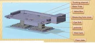
A base unit is the unit designed to mount all the other units(Clamp unit, Pin unit, rest unit etc.) of the tool, also other parts necessary for a tool like pneumatic valve box, trunking cable path will also be mounted on to a base unit.
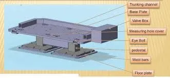
A clamp unit is a unit designed to clamp/hold the car panel with NC blocks/Mylars/rest by using a pneumatic cylinder. Clamp arm, finger, Rest/backup, L-block, shims, riser, pneumatic cylinders are the typical parts of clamp unit. Clamping force should be considered while designing clamp unit. Usually clamp open position is 90o.Fingers are attached to clamp Mylar. In Clamp unit shim to one side is more enough because it will restrict translation motion in upward direction and downward direction only. There is another type of clamp unit known as swivel type. There is pivot pin around which clamp arm rotate.
These units are used to rest the panel. Take an overview of the working height if you're having manual welding. For robotic welding also it's important to see the working height in consideration of the robotic gun, turn table height if manual loading is done. Put the proper gun at the spot location for all the spots near the rest unit. If process engineer has gun shape stick to X, C, Y type of gun. Do the proper gun study and place the gun as per the Geo or re-spot decision and operator approach. Once basic gun is placed considering the throat depth and throat gap start building the clamp and rest block at the PLP.
Fixed pin unit is a unit designed to locate the car panel using pins. Pin, pin retainer, shims, blocks, blade, riser are the part of fixed pin units in general . pin retainer is used to hold the pin firmly.
18. What is a Dump Unit and what are its functions?
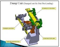
Dump unit is the complex unit to design due to space constains there is less space avilable & have to adjust all the parts in available space. It consist of dump cylinder to perform the operation of clamping & unclamping car panel. Dump units are used when we can not use normal units like clamp unit, pin unit etc. Due to some space constraints. The designed parts should be small in size but can do their functions effectively.
19. What is a Slide unit? Mention where Slide units are commonly used.
Slide units are used at places where there are space constraints and places where there is less accessibility. Sometimes, there are too many small panels near each other and there is not enough space as each panel requires resting, location using 2 pins, clamping and sensing. They are positioning units which are used to position the fixtures, weld gun, units, robots into position for further operations. they are as follows: 1)hardened guide ways. 2)LM guide way. Slide units can be calssified into three types on the base of the prime mover used.