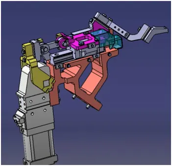
Week 3:- BiW Fixture Design Methodologies Challenges
What Is Design Methodology?
Design Methodology is nothing but the steps followed during the concept designing of fixture design. Below are the steps followed during the design methodology.
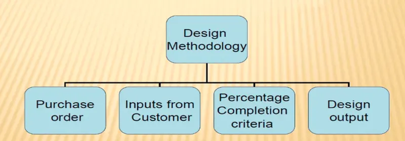
Purchase Order: A purchase order (also referred to as a PO) is a contractual agreement between a purchaser and a supplier that becomes legal once the details of the purchase order have been accepted by the supplier. It is a document that details the goods or services that the buyer has agreed to buy and the terms of the purchase. The purchase order helps a business to keep track with what has been bought as not only does it detail the items purchased but also provides a purchase order number that will correspond with invoices and delivery notes.
Input from customer: Input from customer are the major inputs that we get from customer, how do we study those input what kind of information and get out of those input, these are the criteria that we mentioned in this particular input from the customer.
Percentage completion criteria:
It consists planning of completion of total project. how many days the project will take to complete. It is followed in designing stage and dispatch stage of the welding fixture. It ensures that how much task that we have decided to complete within the stipulated time is complete or not and how much of its rest to complete and whether it’s going to be complete or not in given time.
Design Output: In BIW fixture design or any industry. We don’t only just design a particular component and just give the CAD file to the customer, you have to give a lot of documents like 3D,2D document, which is the detailing part and as well as other factors well like BOM, BOM bill material and other document as well about this particular component and their standard all has to be submitted to the customer.
Q) What are the inputs required from the customer to start designing a fixture?
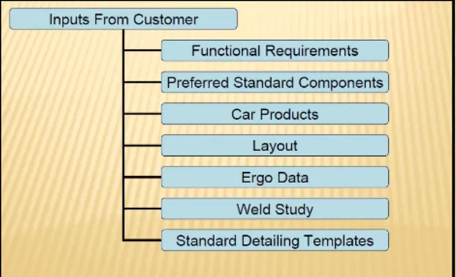
Functional Requirement: In functional design requirement this is basically what kind of functional that particular design going to have for example welding, Gluing, riveting fasting this kind of information will be given us.
Preferred Standard Components: We have to consider as much as possible standard component in our design because it will save our money as well as time also. Some time some of the component customer already have so we no need to buy one more time. For different company using different standard for their component. If we are using standard component then we can easily buy standard component from outside of the market as per our requirement.
- Standard like ABB, NAAMS, FAUNC, FESTO, TUNKERS
- Standard parts like riser L-block, retainer, pins many other companies actually manufacture this
- Some component like clamp, cylinder, slider, switches, sensors.
- Weld guns, Tip Dressers, Tool changers
Car product: Car product like 3D files, read files as well as to learn and to study what kind of geometrical tolerance and what kind of PLP points (Principle locating points) where we can fix those pinion edge and or the clamping edge and then putting position.
Layout: Layout provided information about flow of parts station pitch, robot station and accessors like tool changers, Tip dressers, Platform height, sub assembly link and loading /unloading sequences.
Ergo Data: Ergo data is basically involved well manual operator are involved and every company has different types of standards for aggregate data, so we will be getting that particular input from the customer so these are the standard that we follow so this kind of Ergo data we get from customer. It provided data regarding loading height, working safety zone of the operator etc as per standard that company follow.
Weld study: Weld study means a study of the particular gun that we are going to use for welding and where are going to weld .so if we are doing spot welding what kind of spot welding, we are going to do a number of welding to the particular component.
Standard Detailing Template: Standard detailing template means every company has different type of standard, so they will give us detailing template about how to detail the particular component and dimension.
WHAT ARE THE INPUTS WE GET FROM CAR PRODUCTS ?
Input get from "Car Products"
Car products like 3d files, read files, as well as to learn and to study what kind of geometrical tolerances and what kind of PLP points (Principle Locating Points) where we can fix those pinion edge and or the clamping edge and then putting a position.
Car Products includes
- GD&T
- Part list
- The revision part thickness
- Cad Files Of Car
- Parts Clamp Plan
- Product Assembly
- Process Sheet
1. GD&T
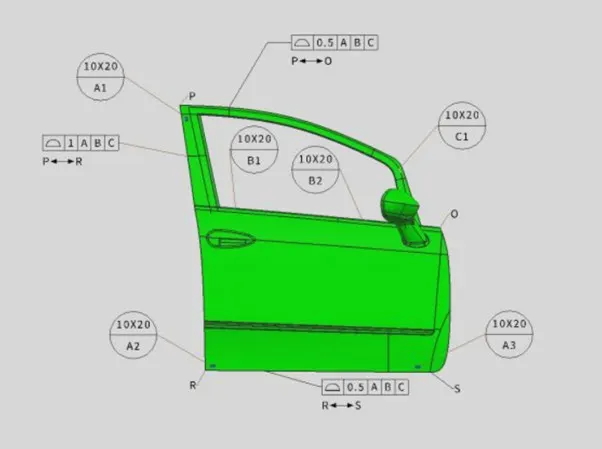
The First Car products include GD and T the geometrical dimensioning and tolerances of the particular parts.
- GD&T provides information on Locating pins, rest, Clamps, Dumps & Slide information of each station.
- The sequence of opening of clamps, dumps, and Slide stroke information.
- In GD & T we will be learning about locating pins so where we can actually locate our pin units and best clamp. How the entire component is gonna rest, or it's going to get clamped and dumb and slide information in each station sequencing and opening of the clamp and slide Strock information.
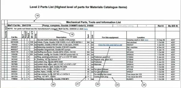
2. Part list
Part list Means what kind of assembly, those parts are going to be.
- For example, the first assembly is going to be between put in a panel and that which is going to get attached. And then the next one will be the hinge. So every assembly will have a different section in it. So, we have to design different assembly parts.
- In the part list, they are part numbers, part names are mentioned. Every part having a different name.
3. The revision part thickness
- In the revision, the first component has 21 divisions. So the cost and patent are revised 21 times. Division of the tooling means the tool as device 30 times, and the pre-production fixture is revised 30 times.
4. Part thickness
- Part thickness is very important in a particular assembly to let's say if you're assembling a part of thickness 1mm,2mm,.75mm, so this will give you what kind of value that you can do, or what kind of gun that you have to use. So it's also a very important parameter to consider.
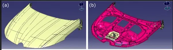
5. Cad Files Of Car Parts
- CAD files of cad products mean the 3d component that we required from all the Cad parts.
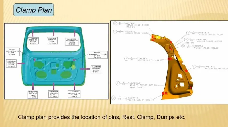
6. Clamp Plan
- Clamp Plam is a very important input that we get in the car products is where exactly we can place those clamping units are the particular pin Units.
- we should never change the position of the particular clamp or the pin, which is given in these data.
- we can change our design a little bit here or there, but we should not change the input design data about the clamp position or the pin position.
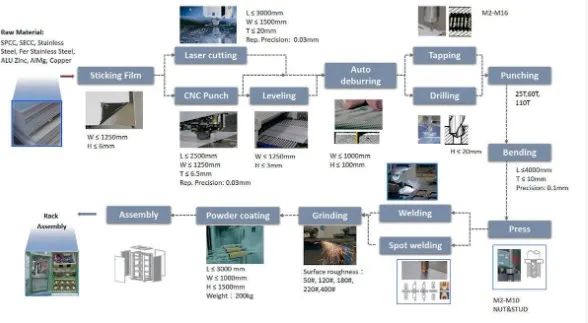
7. Product Assembly Process Sheet
- In the Product Assembly Process Sheet what kind of products we are going to assemble in that particular component or the particular Unit.
What is the Clamp plan?
It is a imp input that isused where the product to be placed the clapming units orthe pin units.
The position of the clamp should not be changed.it should be kept stable at that first position only (pin unit)
as per the given input.
we can change the desgn created by us but never has the permission to change the positon of the clamp input given by the customer it may faces the lot of errors.like it may damages the tool or the clamp while changing.
What is the purpose of a Layout?
5.PURPOSE OF LAYOUT-
The purpose of layouts is to distribute the amount of space given to the view on which they are installed among the children of that view. Each subclass of Layout has a specific pattern of space distribution (a line, a 2D grid, etc.). See their documentation for details.
The layout sheet is the plan of arrangement of the robots, fixtures, assembly parts, jigs work space etc. on a specified area. so that the robots should have some rotational free space to move freely the robot will move about some distance from it position to do the operation like welding fixing, assembly etc. the robot reachable area is called as swept area of that robot.each robot has its own swept area.
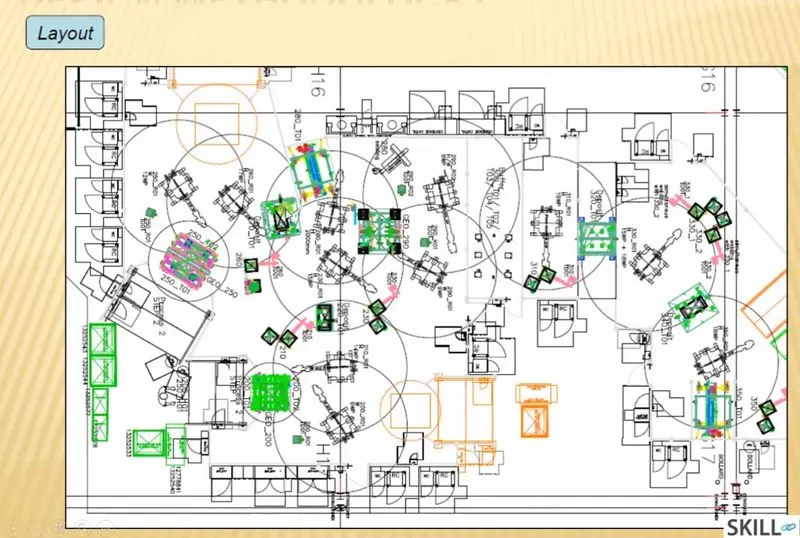
Layout provides information of
- Flow of parts
- Station pitch
- Robot stations
- Acessories like tool changer & tip dresser
- Sub assembly links
- Plat form height
- Loading unloading sequence /heights
FLOW OF PARTS: It is used to move the part from one station to the other station for doing the required operation
STATION PITCH:The distance b/w the two stations
ROBOT STATIONS:The position of the robot which is fixed at that particular position.
ACCESSORIES LIKE TOOL CHANGER & TIP DRESSER:
The required tool is changed accordingly as per the need by the movement of the robot The tip dresser is used to shapen the weld gun required.
SUB ASSEMBLY LINKS
PLAT FORM HEIGHT
LOADING UNLOADING SEQUENCE /HEIGHTS.
What is ERGO data?
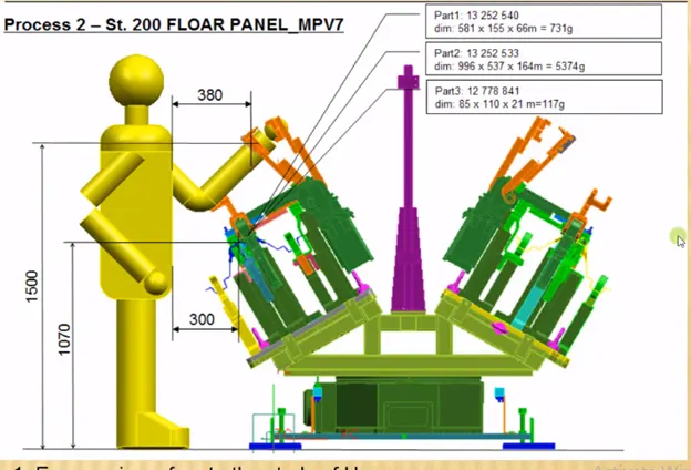
- Ergonomics is the application of psychological and physiological principles to the engineering and design of products, processes and systems. The goal of human factor is to reduce human errors, increase productivity and enhance safety and comfort with specific focus on interaction between human and rhing of interest.
- In any operation, the workers or operators at attain various postures, exerts force and work continuously in a cycle time to perform a particular task. This may cause high level of strain to the operators. To avoid the principle of ergonomics is applied in every operation wherever interaction of human with machine is involved.
- So, the ergo data is the input which gives human factors engineering data between operator and its working environment.
- It has various benefits like improved working conditions, reduce physical workload, improved work postures, reduce efforts of certain movements etc.
What do you understand by Weld study?
- weld study means A study of the particular gun that we are going to use for welding and where we are going to weld. So if we doing spot welding what kind of spot welding we are going to do a number of welding to the particular component.
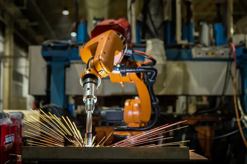
Weld Study includes
- Weld Gun Details
- Weld matrix and weld points
- Geo weld points and Respot Weld Points
1. Weld Gun Details
- This involves the study of the gun. So this is one of the examples of a welding gun, which is used in assembly. So weld study includes weld Gun detail weld matrix and weld points.
2. Weld matrix and weld points
- Weld points are basically where the welding is going to happen at which point at which coordinates are going to happen.
3. Geo weld points and Respot Weld Points
- The data of weld Metrix and weld points will be given to you in the form of spears i.e Green and red Spears.
- At that point, welding is going to happen.
- Geo spots are Red in Color and Re spots are Green in color. All the red spheres are going to happen in geostationary.
What are the criteria for percentage completion in the designing stage? Explain it in detail
- ercentage completion criteria are basically schedule. What time we can complete the entire process again this is more detailed. So when we are going to complete the entire design, then we're going to move on to simulation on all these subcategories would be considered in percentage completion cafeteria like a probability to when we can complete the entire fixture design.
Percentage Completion Criteria is followed in the designing stages and dispatch stages of welding fixtures.
- 0-25% Input and concept design
- 25-40% Concept approval and simulation
- 40-85% Design freezing and detailing
- 85-100% Check and Final dispatch
- Percentage completion criteria are followed in the design stages and dispatch stages of the welding fixtures.
- For example, where the how much of the task and how much of the project that you have already finished and is it actually lining up with the schedule that you have planned before. And these are the information that we get from particularly a percentage completion criteria.
1. Input and concept designing - 0-25%
- In this, they were given four days to design the fixtures that mean we have to complete 25% of the task within four days.
2. Concept approval and simulation - 25-40%
- The concept of design is approved here, and the simulation check is done here, which is 25 to 40% of your design is complete in Comcept approval and simulation.
3. Design freezing and detailing - 40-85%
- In this process, the design is getting Freeze. That means the design is getting finalized. And the detailing is going to start again. Once the detailing is finished, and the design is also feezed that means you have completed at least 40 to 85% of the task.
4. Check and Final dispatch - 85-100%
- This stage is the final stage, Here checking the quality check usage and the final dispatch, which is the output that we are going to give to the customer, which is from 85 to 100%.
Brief about "Output" in design?
It is a 3D model and the 2D drawings of the tools. The tools are divided in two parts-
- Unitized tools- In this multiple units are crated on the common base. It required two types of drawing sheets.
Key sheet-consists of an index of units and their placements.
Layout sheet-A detailed drawing of individual units to includes all of their components
2. Not-utilized tools-It is tools that work alone and can be detailed completely on a layout sheet.
The design output should compile the following information
- Approved standard components are to be used wherever possible in the design.
- Design must be very simple and economical as much possible.
- Design must comply with all current safety and ergonomic (less effort) requirements.
- Desing must be fully controlled and easy work flow with free handling of product.
- The weight of the moving must be kept to minimum and same time strength must be sufficient.
- Design clearance and accessibility must be provided for the routine maintenance and service.
- For moving equipment, motion control must be considered.
- Designer is responsible to validate clamps and all weld guns.
What do you understand by structuring a design tree? How does it reduce errors during the design process?
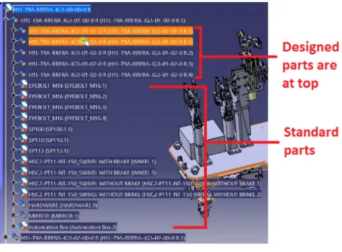
The design structure tree must be defined properly to avoid any mistakes in the design. It is a process where all the assemblies/parts are named in a specific standard. Different customer has their own different set of standards to provide the design tree. It is an important process in designing to identify a specific part/assembly to a certain project.
A proper design tree avoids the mistake/error during the process, manufacturing, assembly and inspection process by providing the specific name to each part based on the project/stage etc. Naming of fixture/unit/part, provides the proper information about to its project, zone, or assemblies.
What are Units? Mention 5 types of units.
- Fixed pin unit
- Retractable pin unit
- Rest unit
- Clamp unit
- Sensor unit
Describe Fixed Pin units & their purpose?
fixed pin unit is designed to locate the car panel using pins. It consists of different part such as pin, pin retainer, shims/spacers, block, blade or adaptor plate and riser as peesented in the below figure.
The purpose of fix pin to resist translation motion and rotatinal motion of the perticular component.
What are the different parts of a fixed unit?
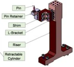
What is the purpose of making a Rest unit & describe its parts?
It is used to rest the components/part on it during the operation. The shim and spacer are used to adjust rest block as per requirement. The riser is used to get the part at the required heights and generally it is used as standard part.
What are the basic fundamentals to design a Sensor unit?
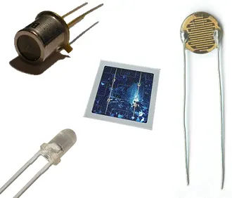
This unit is designed to sense the position/weight of part/components. Once, one process is completed and signal will be sent then only second operation will start. This will avoid any accident during the operation. Different types of sensors such as proximity sensors, laser sensors, photo electric sensor etc. used in automobile industries. Every single loose panel are joining together should be sensed. For big panel, the sensors must be mounted diagonally for better response and it should be 3 directions adjustable.
A sensor is a device that produces an output signal for the purpose of sensing a physical phenomenon.
What is a rough locator unit & what are the basic fundamentals to consider while designing it?
It is part designed to guide the operator to locate the car panel on to the pins as per the requirement. A rough locator can be of standard part or make part.
Point must be considered
* It is placed at the edge of the car panel, which it has to guide.
* It must be placed in the same angle with the car part edge with a minimum distance of 2-5 mm from the edge of the car part.
* It should start guiding the panel before 10-15 mm to the start of the pin engagement.
* It is designed with entry angle for car part entry.
* The slots should be in the direction of car part guiding.
What is a Base unit and describe its parts?
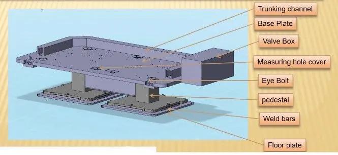
Base unit is used to mount all the units on it for any operation. Under it eyes bolt is used to lift or carry base, and stool used to provide the required height. Base plate is used to mount unis/parts. Its height must be designed as per the operation whether manual or robotic. For the manual working condition height should be in range of 850 mm to 1100 mm. It designs should deflection less and vibration free.
A base unit is the unit designed to mount all the other units(Clamp unit, Pin unit, rest unit etc.) of the tool, also other parts necessary for a tool like pneumatic valve box, trunking cable path will also be mounted on to a base unit
What is a Dump Unit and what are its functions?
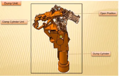
It is used for complex region where simple unit cannot be fixed. The weight of the dump unit must be less as much as possible, it helps to reduces the forced required. It can have more than one cylinder to perform the complex operation. In this unit make sure that in open condition of the panel, one should be able to remove the panel.
What is a Slide unit? Mention where Slide units are commonly used.
Slide units are positioning units, which are used to position the car part or panel, units, weld gun, robots for further operations.
Slide units may be classified into two types based on the type of guide ways. They are,
- Hardened guide way.
- LM guide way
Slide units may further classified into three types based on the prime mover. They are,
- Manual slides
- Hydraulic/pneumatic slides.
- CNC slides
It may be further classified depending on the application as
- horizontal slide unit
- Vertical slide unit
- Angular slide unit