BiW Fixture Design Methodologies Challenges
BIW FIXTURE DESIGN METHODOLGY
Design Methodology is the series of steps followed during the concept design stage of Fixture design. The Principal objective of any design process is to provide a suitable framework and methodology for the definition of the sequence of activities by identifying the requirements along with associated constraints
The basic terminologies followed in Design Methodology are
- Purchase Order
- Input From the Customer
- Percentage Completion Criteria
- Design Output
CUSTOMER INPUTS
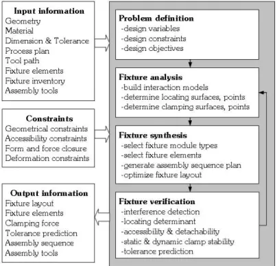
Every customer has specific requirements based on their own raw materials, Standards and gives input to the Fixture designer. The inputs are classified as
- Functional Requirements The design of machining fixtures is a highly complex process that relies on designer experience and his/her implicit knowledge to achieve a good design. Hence, the functional requirements and their associated constraints should be the first input to any design process.
- Preferred Standard Component has details about all clamping cylinder and fixtures standards. Bought out item (Purchased parts) standards like pneumatic items, toggle clamp, bearing, screw, dowel etc. company information
- Car Product details about PLP (Principle location scheme) of the individual panel and total assembly. CAD panel data or 2D drawing of assembly and individual panel data
- Layout Information has Process sheet if Process engineering is done - where loading sequence, no of clamp data and gun data is mentioned.
- Ergo Data Information about the Factory working procedure, Operation Ergonomics and Expected Cycle Time are provided
- Weld Study Inputs like Sheet metal panel thickness and Spot Detail information, total no of spots and spacing between the spots and Weld information clarity from drawing like 2 metal or 3 metal welding are provided
- Standard Detailing about CAD -Software guidelines, Raw material standards, Design guidelines Bill of material (BOM) of the components
CAR PRODUCTS
Car Products basically has all the inputs regarding the technical details for the Car parts that the fixture is being prepared. It Includes
- GD&T
- Part List
- Cad Files or Car Part
- Clamp plan
- Product Assembly Process Sheet
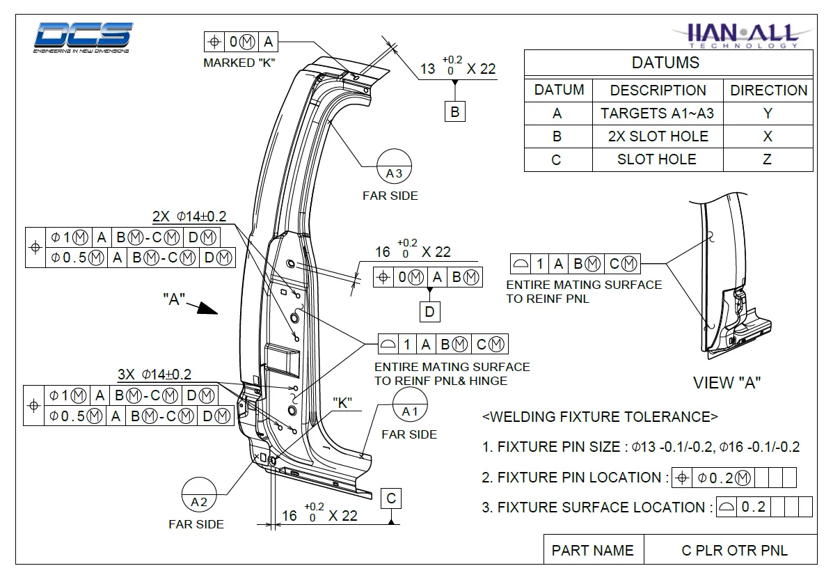
GD&T
GD&T Provides information of Locating pins, Rest, Clamp, Dumps and Slide Information of each station
It also provides details about Sequence of opening clamps, dumps and slide stroke information.
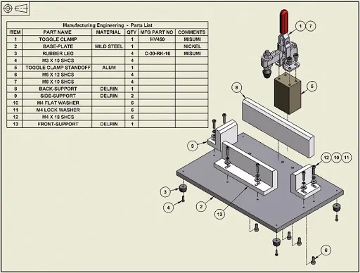
PART LIST
This details about the various features for specified parts in a list and has all necessary information about individual parts in the assembly like spot welds required and location points desired, part thicness details, Part number etc,.
CAD FILES
Additionally to GDT drawings classified 2D CAD Draft sheets are provided for fundemantal understanding of fixture design with locating holes, Datum Targets etc,.
CLAMP POINTS
Clamp points provide the location of the pins, Rest, Clamp and Dumps.
Clamp points and Weld Positions suggested by the customer should never be modified by the designer without any prior approval.
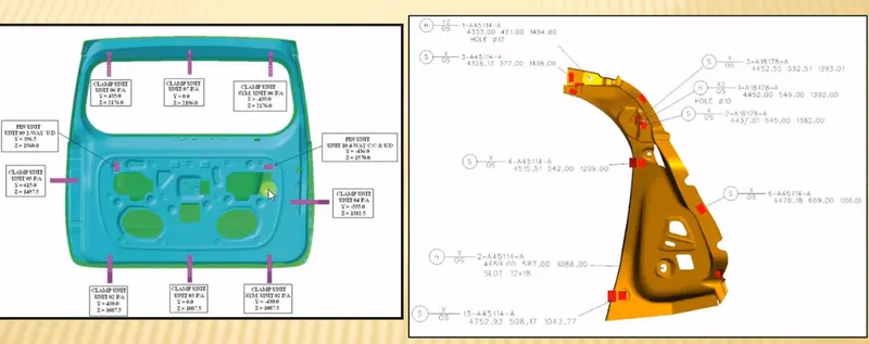
Clamping specifications provided by the OEM
PRODUCT ASSEMBLY PROCESS SHEET
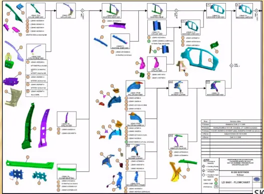
This gives the details about how the components are going to be assembled together and an instruction sheet or product sheet will be specified for the designer to follow the instructions
LAYOUT
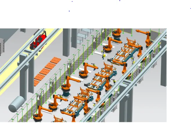
The Fixture Design layout depicts the plan of layout with details of flow of parts from one staion to another station with necessary space constrains and tool specfications.
Purpose of the Layout is to identify the flow of parts and to get data about the space of the Base Units with sufficient information about the Flexible Operation of Material Handling Grippers and Lifters.
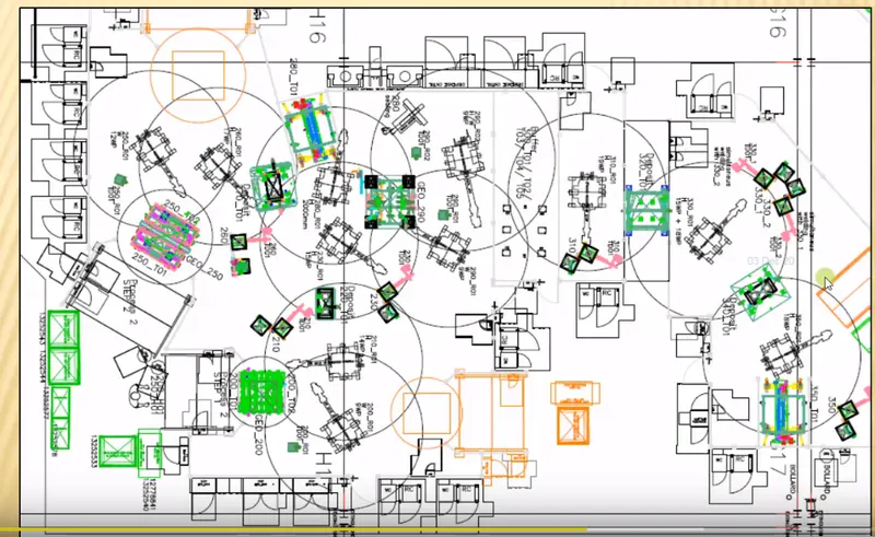 LAYOUT of the Shop Floor
ERGO DATA
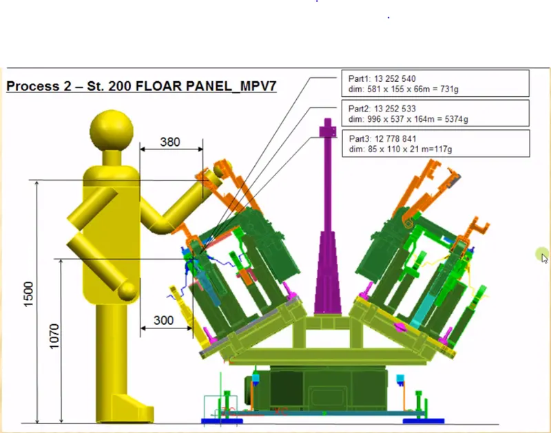
The ergo data refers to the study of the human behaviours and movements in the factory which provides information about
- Loading Height
- Working Safety Zone of the Operator
- Stand height
WELD STUDY
Weld Study is done to identify weld gun details, weld matrix & Weld points and to classify the Geo Weld points and Respot Weld Points.
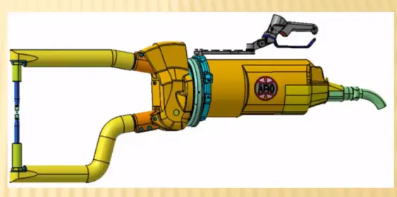
They are marked visually in different colour to differentiate between the weld tack stations.
Spot Detail information, total no of spots and spacing between the spots and Weld information clarity from drawing like 2 metal or 3 metal welding are provided.
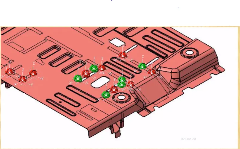
Red Points represent Geo Spot Weld, Green Points represent Respot Welds.
PERCENTAGE COMPLETION STAGES
The percentage completion stage is used to identify the achievements of critical milestones along the project. Thus based on the duration and completion of different stages a Chart is prepared which helps in keeping the Fixture Design Activities on course with the Takt Time defined by the customer.
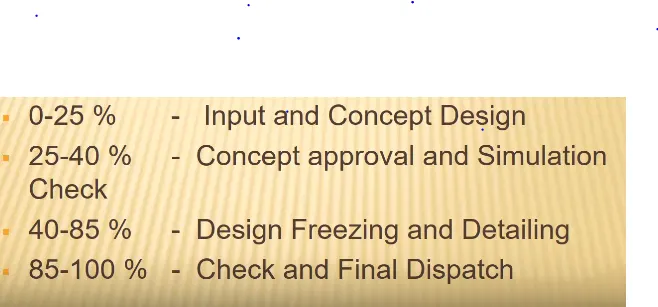
Takt time is the heart beat which defines the rythm of the proccess and is usually set by the customer. The Fixture design stage has to devise a calculation of time required for completion of the above four stages and should match that lead time with the takt time for on time delivery of the Product
DESIGN OUTPUT
Design output consists of 3D modes and 2D Detail Drawings.
It consists of Unitized tools and Non Unitized Tools.
Unitized Tools has two types of drawing sheets they are
Key Sheet: An Index of units and their placements on the tool base. It represents the location of tool and its specification
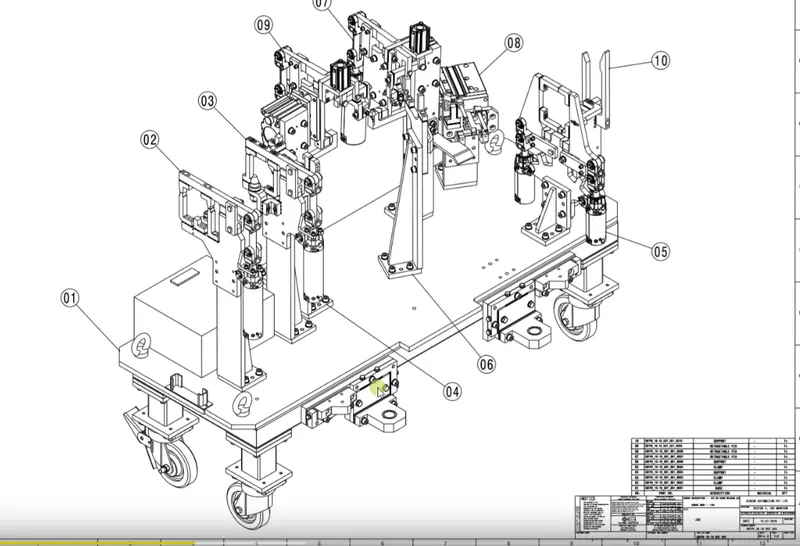
Layout Sheet: A detailed drawing of individual units to include all of their components
Non Utilized Tools are standalone output defined completely on a layout sheet. They are stands, and other support tool.
The Following details should be mentioned in the output sheet
- Approved standard components are to be used wherever possible
- Design must be simple and easy to understand
- It must comply with all standard and ergonomic safety requirements.
- Adequate Error Proofing provision should be provided in each design
- The Weight of the moving part should be kept to a minimum while maintaining maximum strength
- Frames and Structures are to be firm and sturdy
- Design Clearance, Tolerances and Stack ups should be ensured
- Designers should validate clamps and all weld guns
The Main responsibity of the Designer and Quality is to resist the vibration and represent adequate details in the output for the OEM to understand during final handover
Structuring Design tree
- Structuring and specification of design tree is vital process in every product design. The classification of different features in separate Geometric Sets with accurate naming as per the flow of the part specification tree saves time of the designer to navigate to appropriate sets during modifications.
- Fixture Design involves design of lot of individual parts assembled together and has similar parts at different position.
- It is essential to name them appropriately in a chronological order as per Organization standard helps to reduce the manual error and having a clean specification tree allows anyone from the organization to access the part design without any ambiguity.
- Usually unique parts (mylar, clamp) involved in the subassembly are positioned above and the standard parts (shims, risers etc,) are kept at the bottom of the part tree structure.
- Nomenclature of Specification tree is standardized for the entire organisation and it might differs from other OEM. The part is named after part number, Zone , Station number, Quantity.
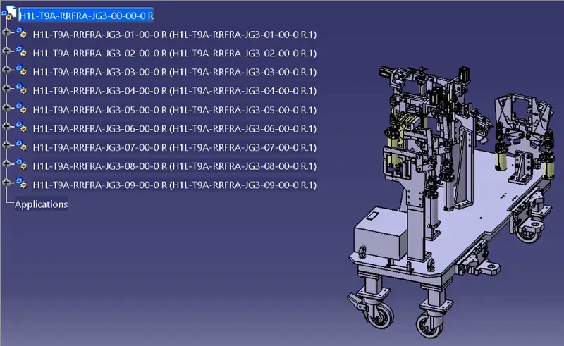
Therefore the purpose of Structuring design tree is as follows;
- Reduces the error while working in the design study, manufacturing, assembly and inspection,
- Saves operation time while navigating through different sets for any modifications,
- Improves clarity of drawings without any redundant design operations.
UNITS IN FIXTURE DESIGN
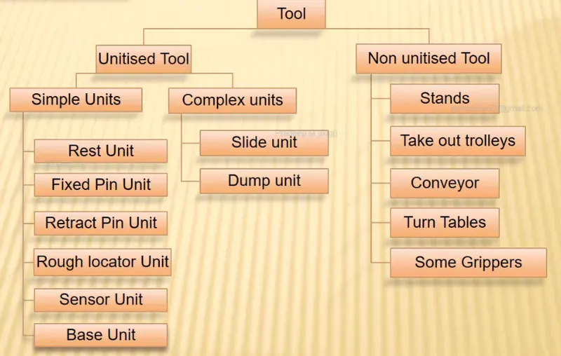
The fixture design involves huge number of parts and with respect to their function they are classified into different units. The units are classified
Non-unitized tool have no process functionality and will used to support the process fixtures Eg: Stands, Conveyors, turn Tables
Unitized Tools are the process units that forms simple and complex parts of the fixture design
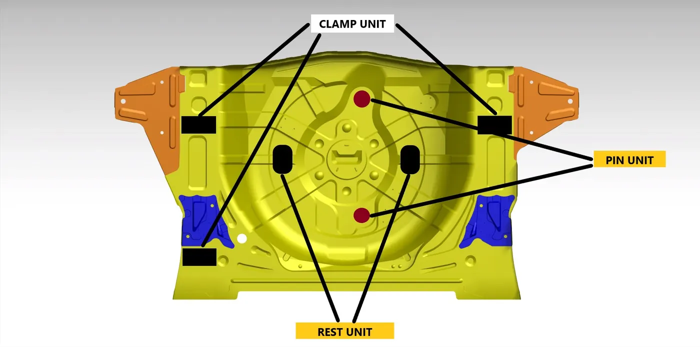
The types of Units are
- Base Unit
- Resting Unit
- Clamping Unit
- Pin Unit
- Sensor Unit
FIXED PIN UNIT
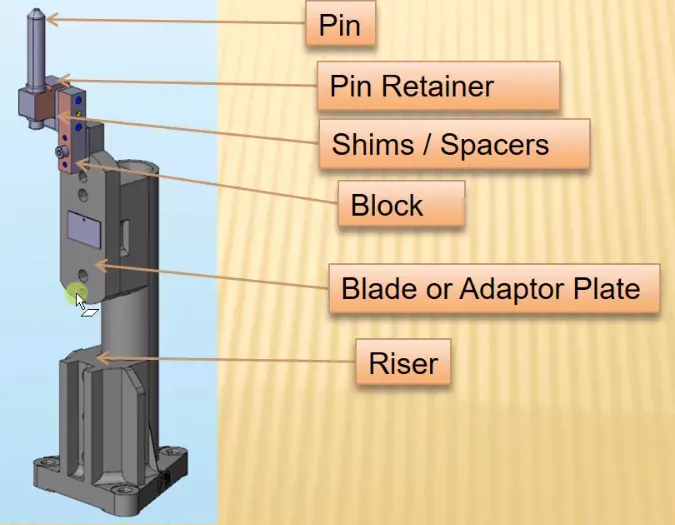
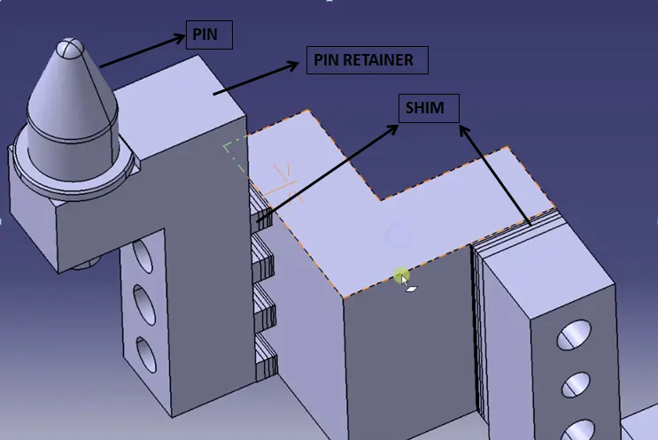
Fixed pin unit is a unit designed to locate the car panel using pins. The different parts in fixed pin unit are
- Pin: Pin is the holding device that touches the panel. The shape of the pin depends upon the mounting hole of the BIW Panel and is designed to have very close tolerance
- Retainer: Support the pins
- Shims: These are parts that are mounted on two way locators to adjust the coordinates of the pin
- Block: Blocks are mounting space for rest of the pin unit
- Adaptor Plate
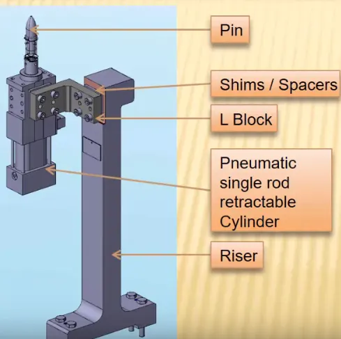
- Riser: Riser are used to lower and rise the pin unit
PURPOSE
Pin units are essential part of the fixture that are used to restrict the rotational degree of the panel and lies in the exact coordinate.
Shims are given in two coordinate directions to negate the stacked up tolerances
The entire fixed unit is placed in a block unit that is supported by the riser.
Retractable Pin unit are used for similar purpose as fixed unit but the difference is Pin will be supported by a retractable cylinder. The main objective of the Fixed pin unit is to maintain the specified coordinate distance specified and has to pass the quality test done by the CMM Machine
REST UNIT
Rest Unit are used to support the car panel using NC Blocks/Mylar/Rest
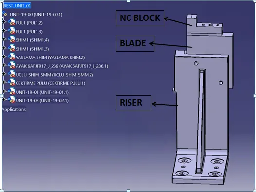
- The rest unit supports the pin, retainer and helps the fixture to hold the panel rigid during the vibration. The resting unit.
- The Risers are used to adjust the height of the fixture based on required coordinates
- The Mylars/NC Blocks helps in holding the fixture parts rigid
- Blades are used for mounting other parts like cylinder,arms etc,.
CLAMP UNIT
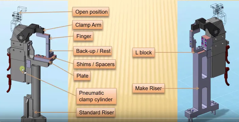
Clamp unit is used to clamp the car panel with Mylar by using a cylinder. The clamp has two positions; opening condition and closed condition. The clamp unit are allowed to open to a specify angle and operarted by pneumatic cylinder
SENSOR UNIT
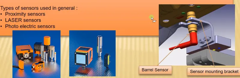
- Sensor unit are used to sense the car panel by using electrical sensors and the signal will be fed to the PLC
- The main purpose of using a sensor panel;
- To detect the loose panel which are to be welded
- They are used to sense the orientation and size and also used to activate the pneumatic cyclinder based on different sequence
- The types of sensor used are Proximity sensor, LASER Sensor, Photo Electric Sensor.
ROUGH LOCATORS
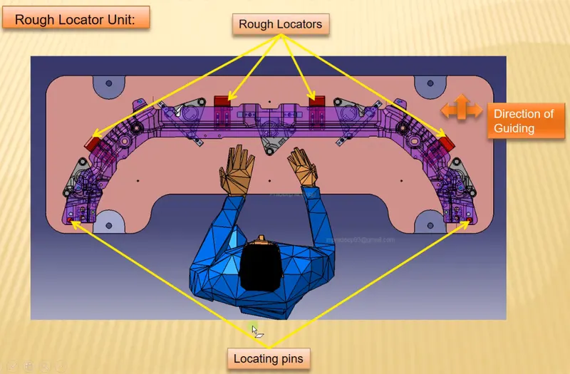
Rough Locators are used to guide the operator to laocate the car panel on to the pins accordingly and it can be a standard part are made part.
Fundementals of Rough Locators Design
- Rough locator should be placed at the edge of the car panel
- It has to be placed at the same angle of the car part edge with a minimum distance of 2-5mm from the edge of the car part and should have adequate gap which prevents from damaging during loading and unloading
- Rough Locator should guide the car panel in the pin arresting direction
- It should be designed with entry angle for cart part entry and should be designed with two slots to mount panel and for easy adjustments.
- Rough locators should start guiding the panel before 10-15mm to the start of the pin engagement
BASE UNIT
Base units are used to mount all other units of the tool along with necessary tool units such as pneumatic valve box, trunk cable path will also be mounted on to the base unit
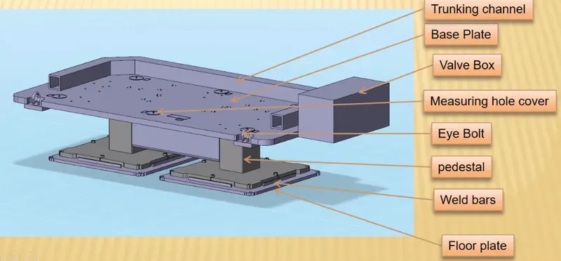
- Valve box are the parts in base unit that supplies air to the cylinder and has solenoid valves to regulate the flow
- The base unit is mounted on the Floor plate using pedestal stand that are welded with the plate.
- Eye bolts are used to lift the base unit

DUMP UNIT
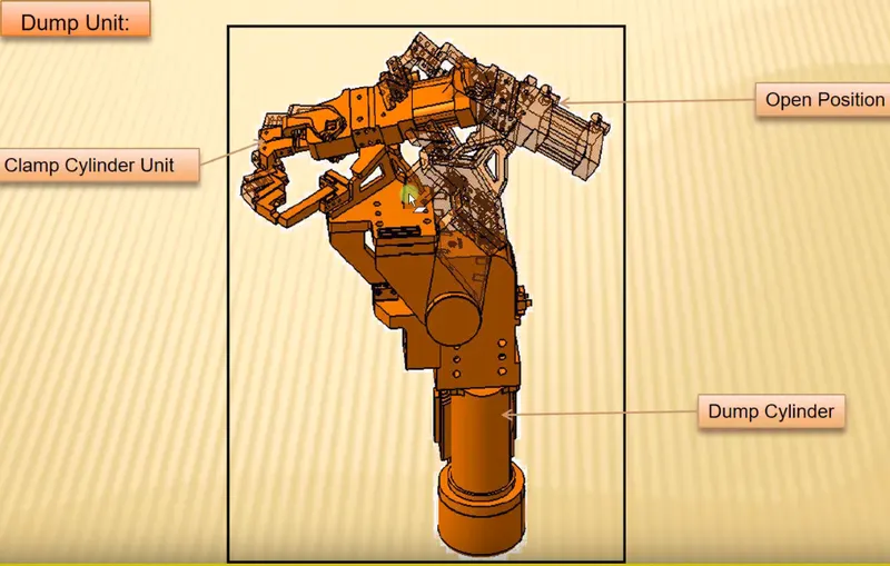
Dump unit is a complex design assembly and is used during some constraints where normal mounting of pins, clamp, rest are not desirable.
Dump Unit
SLIDER UNIT
Slider unit is another complex fixture design which is used during space constrains and help to position the fixture
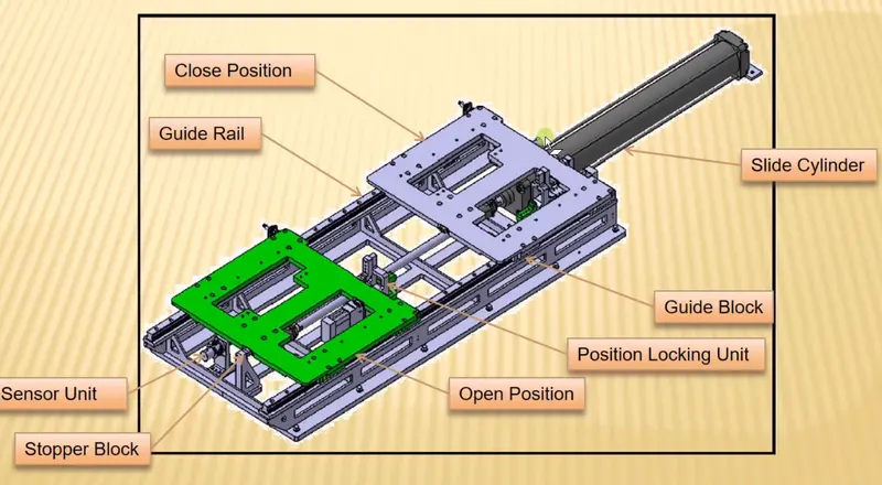
Slider Unit
Based on the type of the guide ways , type of the prime movers used the Slider units are classified as
Hardened Guide Way
LM Guide Way
Manual Slides
Hydraulic Slides
CNC Slides
The frictionless guide ways are usually used to position the car part and has cylinders, stoppers, sensors, locking unit
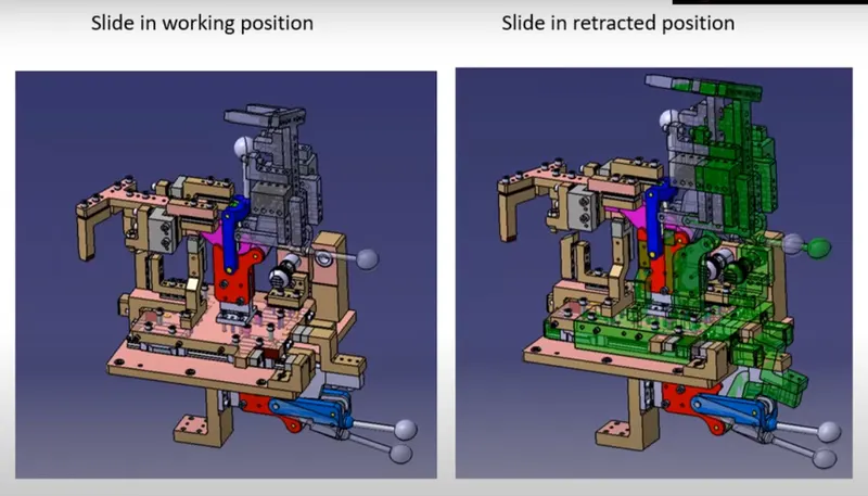
Slider for movements
For Instance,Slide units are used for moving the weld guns from one point to the other when robotic weld guns are not used
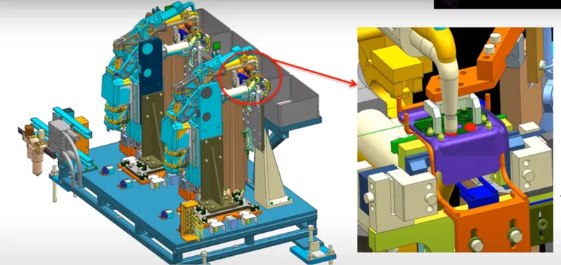
Enlarged view of Weld spot
CONCLUSION
The Fixture design methodologies and various basic terminolgies used in fixture design are detailed in the report.