Hood - Shell Meshing and Mid Surfacing using ANSA
Week 3 : Sheet metal Hood Shell Meshing and Mid Surfacing using ANSA
AIM
Perform geometry cleanup , extract midsurface and shell mesh the given hood assembly according to the given parameters.
Given Quality Parameters.
| Target/Average length | 5 |
| Minimum Length | 2 |
| Maximum Length | 7 |
| Aspect Ratio | 3 |
| Warpage | 15 |
| Skewness | 45 |
| Jacobian | 0.7 |
| Min Quad Angle | 45 |
| Max Quad Angle | 135 |
| Min Tria Angle | 30 |
| Max Tria Angle | 120 |
| Tria Percent | 15% |
Brief explanation of why these quality parameters needs to followed during mesh generation.
Aspect Ratio
- The ratio between largest and smallest dimension of an element is known as the Aspect Ratio.
- Ideal value is 1. In this case 3 is followed as achieving ideal value is tough due complex geometry.
- Along with solution accuracy the poor element shapes will often cause convergence problems in nonlinear analyses.
Warpage
- Angle of plane deviation in an element , in this case the acceptable value is 15 degress.
Jacobian
- It is a factor arising when elements needs to be converted from local coordinate system to global coordinate system. Ideal value is 1 , acceptable value is 0.7.
Skewness
- It is a measure of distortion of the elements based on angle. Lesser the difference between angles of vectors drawn towards the center of the element better the mesh quality.
Procedure
- Given component is a sheel metal, since sheets have uniform thickness - Measure tool was used to find out the thickness of all parts in hood assembly.
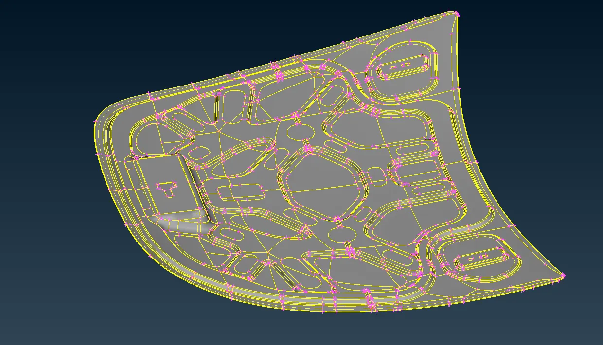
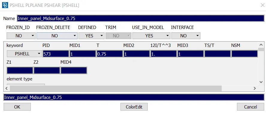
- The parts and their thickness are Inner Panel (0.75mm) ; Outer Panel (0.75mm); Hinge Reinforcement ( 1.2mm) ; and Latch (1.2mm)
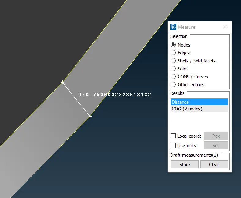
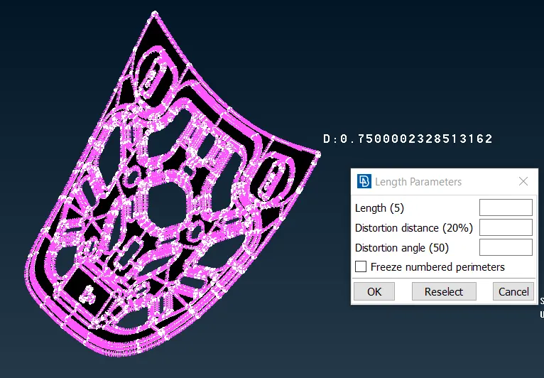
- Once the the Parent model has been imported to the ANSA UI , Increase the resolution of the model using the length option in the Mesh module.
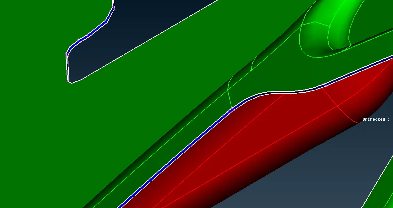
- Topo Clean up - Perform a Gerometry check to make sure face connectivity is present by avoiding single cons (red ) , cracks, Overlap faces, Needle faces, Triple cons in the parent CAD.
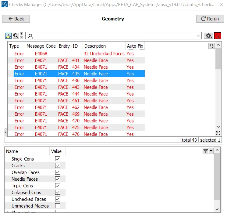
- Fix the above mentioned issues with geometry and fix them up.
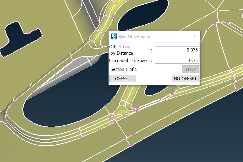
- Next step is to extract the Midsurface for 2d shell meshing.
- Midsurface can be manually extracted using the offset option or by using Mid.Surface Skin by aid of ANSA.
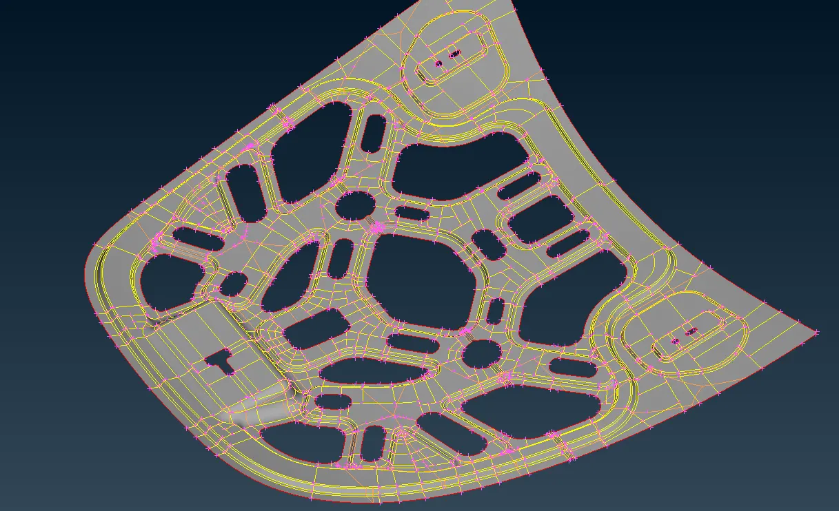
- Orient the faces for the preparation of the meshes.
- Perform a Topo and again make sure to avoid single surfaces , duplicate faces. Single cons is acceptable at the perimeters since it not a closed volume.
- Mesh Parameters needs to be defined in this case the target length is 5 , set the min and max length. Element type as mixed.
- Quality parameters also needs to be saved along with presentation parameters as listed in table above.
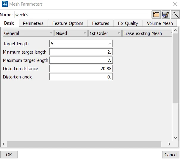
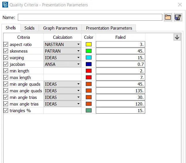
- Mesh Generation - Using Perimeters panel set the mesh length across the perimeter and the macros of the mid surface.
- Perform defeaturing to regions where the mesh length can fail.
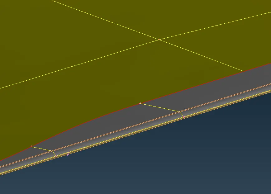
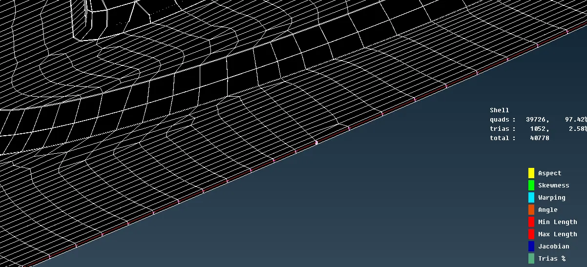
- The above pic is from the outer panel of the hood , the fillet had to split in order to accomodate the mesh target size.
- Using Cut and Join in option in macros tab, divide the surfaces into smaller regions to generate decent mesh flow as well as avoid trias.
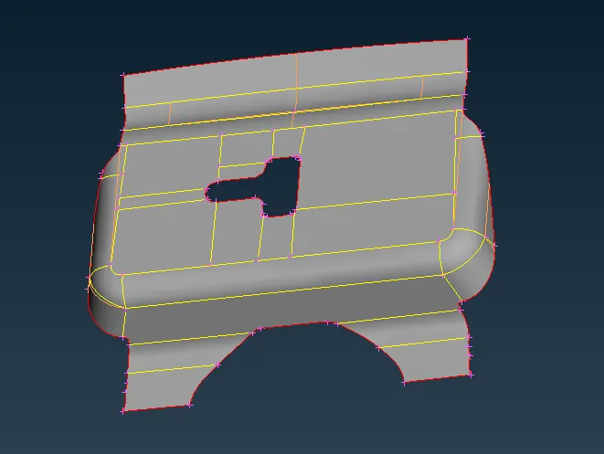
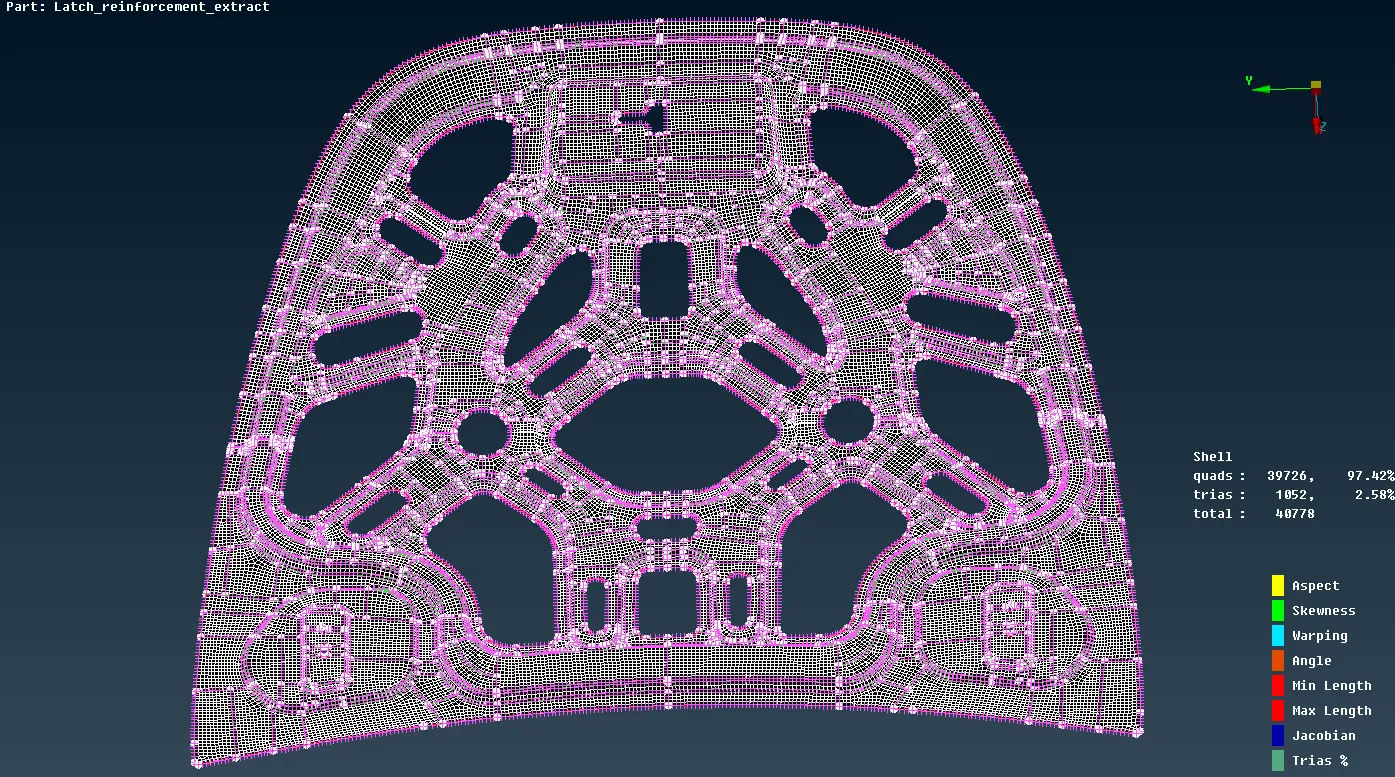
- Perform Best mesh of the sufaces. ( use coarse mesh for complex faces and finer mesh for simpler parts)
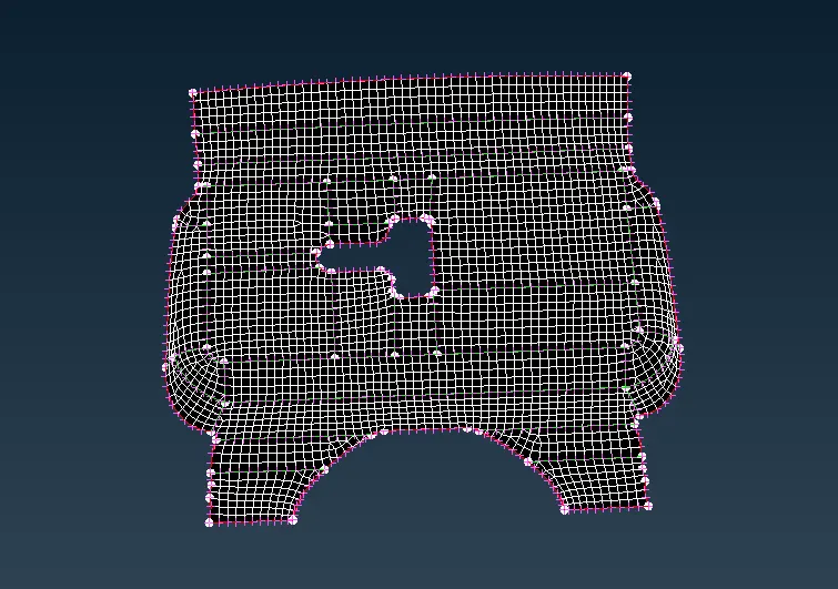
- Use Reconstruct and improve option for improve the mesh flow and remove any quality fails.
- Use Smooth for to remove zig zag mesh flows.
- To deal with trias which facing opposite and towards each other, split, join, swap as well as paste option in grids can be used to reduce the trias percentage in the FE model.
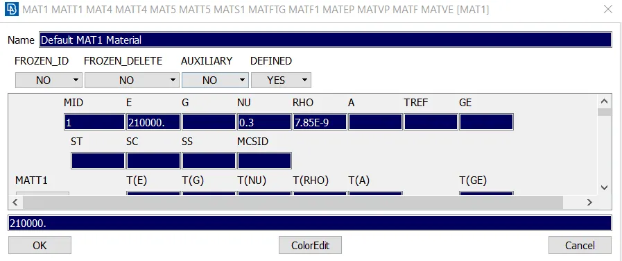
- Assign material and thickness to the mid surface generated.
Conclusion
- Midsurface was extracted and the given quality parameters were met.
- Tria percentage level and rotating quads were avoided to acceptable level.