Week 3
Objectives:
- To clean up the given topology of Hood geometry using ANSA.
- To mesh the given model using proper meshing tools.
Procedure:
Generating mesh for any geometry is a two step proccess
- Cleaning of the given topology
- Mid surface Extraction.
- Mesh generation
- Quality clean up
- Thickness assignment
The following tools were used in the meshing process:
Topological tools:
The different tools that were used and there functions are given below:
(1) Cut: This function cuts (splits) an existing Face or joins if inverse operation is applied (right mouse button). In order to achieve this, two Hot Points must exist on the boundary at the positions where the Face has to be split. A Face may also be cut by selecting Welding Spots instead of Hot Points.
- Heal Cut: it is an option that allows the user to close openings along the perimeter of a face.
(2) Delete: This function deletes selected Faces. As the Face is deleted the neighboring topological conditions change. If the picked Face to be deleted serves as a parent Face to other linked Faces, then extra confirmation is required for the deletion, and an option to convert all linked Faces to geometry is given.
(3) Topo> Faces> New: This function defines a new surface by selecting its boundary curves and creates a corresponding face that covers the new surface. The calculated surface appears as a net. The majorily used options under these settings are:
-
COONS: This function defines a new multi-patch Face and Surface, using the COONS interpolation principal. This is an easy way to define a new surface by its boundary curves. After the mathematical definition is finished, the calculated surface appears as a net. A relative window gives the ability to accept or to reject the calculated surface. When only three boundary sides are selected, there is the ability to choose between two alternative definitions for the fourth generated side, one is to be straight and the other is to have a shape similar to its opposite side.
- FITTED: The FITTED option is used for the definition of a non-planar Face. The created Face fits to the selected boundaries.
(4) TOPO>Hot Points>Parametrical: This function defines a new Node or Hot Point parametrically on a 3D-curve segment or a CONS segment. The input parameter value may vary from 0 to 1, describing the percent of the length of the 3D-curve or CONS. Alternatively, it can be an exact value of distance with a prefix (~).
(5) TOPO>Faces>Topo: This function automatically creates topological conditions between selected adjacent CONS.
(6) TOPO>CONS>Project: This function projects, as CONS or 3D Curves, a number of selected 3D-curves, CONS, element edges, line elements or Hexa Box edges on a number of selected Faces, in a user controlled direction. The selection of the CONS or 3D-curves can be assisted by the 'Corner Angle', 'PID Neighbs' for line elements or 'Path'.
(7) TOPO>CONS>Release: This function releases CONS which have been automatically joined (pasted) or were joined by the CONS>Paste function.
(8) TOPO>CONS>Paste: This function pastes (joins together) two or more CONS segments that lie close to each other, and which usually are boundaries of different Faces. A new topological condition is created and these Faces become neighboring.
(9) TOPO>Faces>Offset: This function offsets selected Faces by a given distance in order to create new Faces.
(10) TOPO>Faces>Mid.Surface: This function turns the solid description of a thin part into a thin shell description by isolating the outer or inner skin of the solid description.
(11) TOPO>CONS>Paste: This function pastes (joins together) two or more CONS segments that lie close to each other, and which usually are boundaries of different Faces. A new topological condition is created and these Faces become neighboring.
(12) TOPO>CONS>Project: This function projects, as CONS or 3D Curves, a number of selected 3D-curves, CONS, element edges, line elements or Hexa Box edges on a number of selected Faces, in a user controlled direction. The selection of the CONS or 3D-curves can be assisted by the 'Corner Angle', 'PID Neighbs' for line elements or 'Path'.
Meshing tools:
Different tools that were used to setup mesh were given below:
(1) MESH>Perimeters>Length: This function defines the element length on selected perimeter segments. The element length may be explicitly declared or may be declared as a factor to be multiplied by the existing element length.
(2) MESH>Shell Mesh>SMOOTH : This function automatically applies Smoothing attributes so as to 'relax' the mesh on already meshed Macro Areas or on FE-model shell mesh. The function may be applied to selected meshed Macro areas (Geometry) and/or FE-model shell mesh according to the chosen sub-option.
(3) Cut: This function cuts an existing Macro Area. Two Hot Points or nodes on the Macro Area perimeter are needed at the positions where it is to be cut.
(4) MESH>Hot Points>Insert: This function defines a new Hot Point, on a Macro Area's perimeter, using the mouse.
(5)Mesh>Grids> MV Free: This function moves a single or a group of nodes freely on the plane of the screen, based on the global, a local or an element'scoordinate system.
(6) MESH>Shell Mesh>Reconstruct: The Re-construction function is a powerful tool for the creation of a high quality surface mesh. It examines a given mesh and performs re-meshing to correct problematic areas and optimize the overall quality of the mesh according to the mesh parameters. For Geometry Mesh (Macro Areas) all modifications are made on the underlying CAD surface.
For FE-model mesh, all modifications are made on the surface defined by the shell elements. The function may be applied to selected or to all visible meshed Macro Areas and FEM mesh according to the chosen option.
With the option "Advanced" the Advanced Selection window opens where the user selects where to apply the Reconstruction. Note that the option "Violating" is associated with the mesh quality creteria in the F11 card whereas, all the rest obey to the Mesh Parameters. The Expand Level controls the number of zones around the affected elements.
Applied on Geometry mesh the perimeters will be visible as feature lines, which cannot change, but the user can add or remove more edges as perimeters. Applied on FE mesh, the user is able to modify all feature lines during preview stage.
(7) MESH>Elements>Split: This function splits quadrilateral and triangular shell elements into smaller ones. Element splitting is performed between selected nodes and/or inserted nodes along selected element edges. The function can be applied on individual or groups of shell elements in order to improve the mesh orientation, reduce the number of triangles, or refine locally or globally the mesh of a part. Refer to ANSA User's Guide for a detailed description of the use of the function.
(8) Mesh>Elements>Swap: The Mesh>Elements>Swap function rotates the shell edge picked by the user, inside the two shells which have that edge as common.
(9) MESH>Macros>Join: This function eliminates a Macro Area boundary segment between two adjacent Macro Areas. This way, two Macro Areas are joined to be treated as one, larger Macro Area.
Initial Geometry:
Mid surface extraction method:
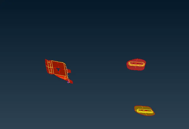
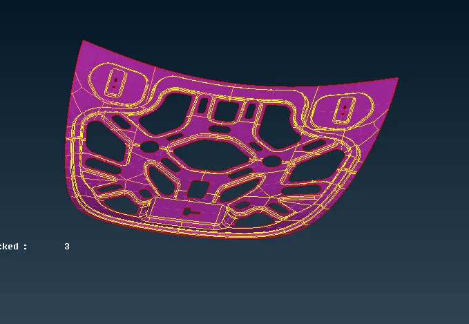
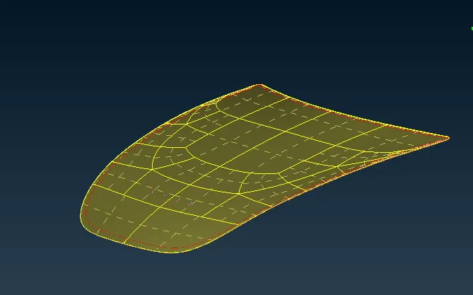
Both offset and Skin option were used for extracting the midsurface. Offset was used in small components and skin option was used in bigger components. since, in sheet metals the thickness of the component is uniform so the skin mid surfacing option will work accurately. Also in the skin option the thickness will be automatically assigned to mid surfaced component.
Middle Surface of hood Panel:
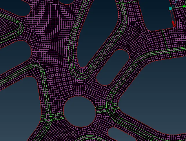
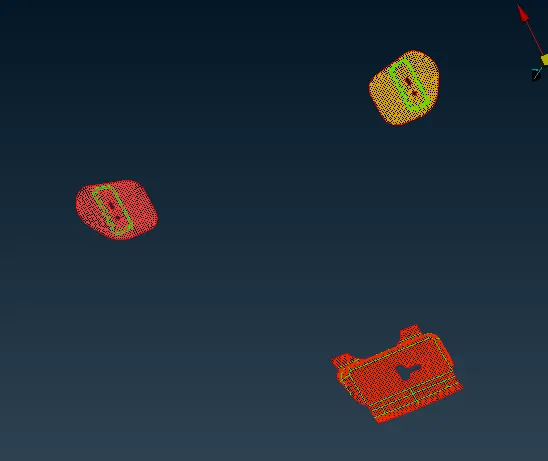
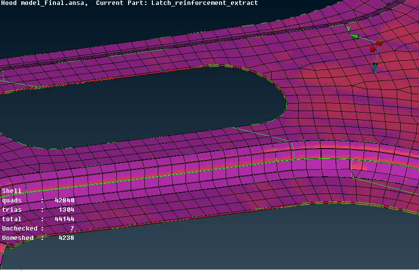
After Meshing:
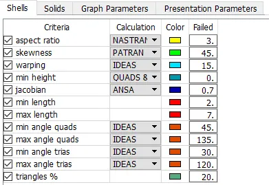
Quality creteria:
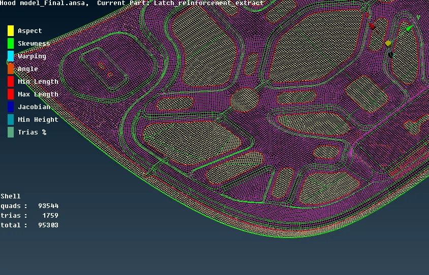
After Element quality clean up:
Assigning Thickness:
Conclusion:
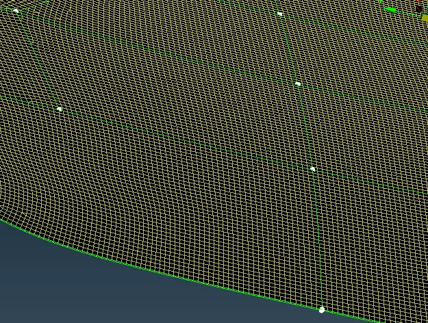
The meshing of the hood was done and the thickness was assigned. Mesh was also released form the geometry.