2D MESHING, MID-SURFACING AND QUALITY CRITERIA (OF HOOD MODEL)
2D MESHING, MIDSURFACING AND QUALITY CRITERIA
(OF HOOD MODEL)
Aim -
- Find out errors and perform Geometry cleanup of the model.
- Convert part to 2dimensional as geometry have same thickness.
- Geometry de-featuring to improve the mesh flow.
- Generate the mesh/net on model under given Quality criteria.
Objectives:-
- Import the given .stp file of the hood model in ANSA.
- Provide proper orientation to the geometry.
- Perform Geometry chech for geometry cleanup.
- Generate mid-surface of the hood model.
- Correct the model cons or defeature model to fit mesh criteria.
- Generate mesh on the 2 dimensional face.
- Reconstruct and generate a smooth flow.
- Remove joints without affecting the mesh structure.
- Release the mesh structure.
Geometry observation:-
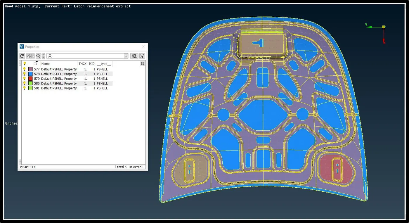
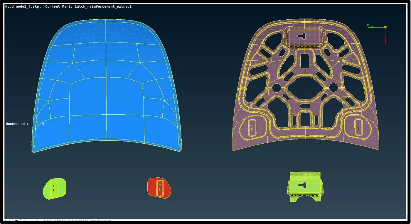
We will start our work by importing the .stp file of the hood model. Which is look as per shown in following figure.
Orientation of the surface:-
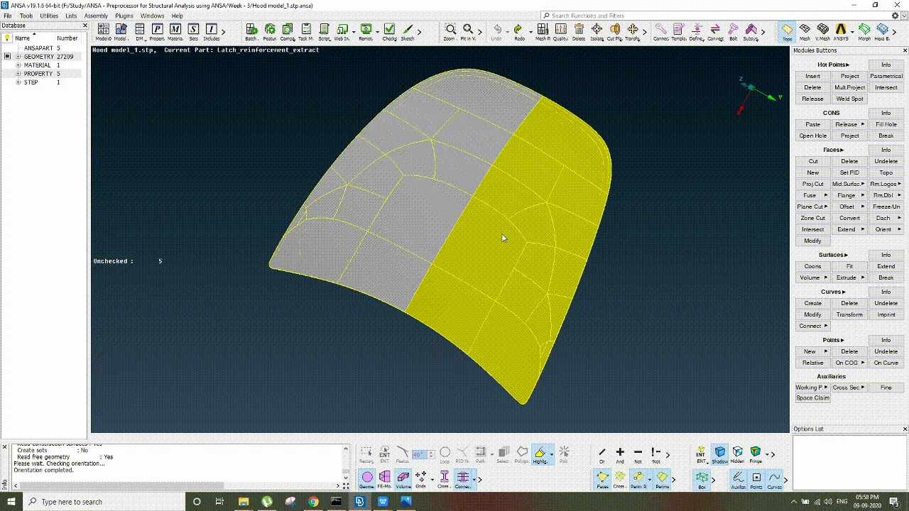
This part is at PID mode but when we set it in entity mode its not perfectly oriented as its show yellow and gray colour surfaces at the same side of the surfaces. In order to orient it in same side (positive or negative) we have to use orient command as shown in following gif file.
PID of individual parts to select required geometry:-
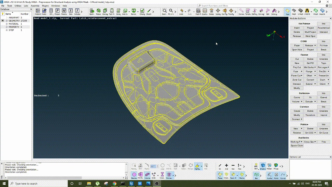
Now, we know there are 5 geometry in this .stp file we can see that by using their property ID's. So turn on the PID mode to see geometries different colour and we can on or off them using PID option.
Geometry cleanup:-
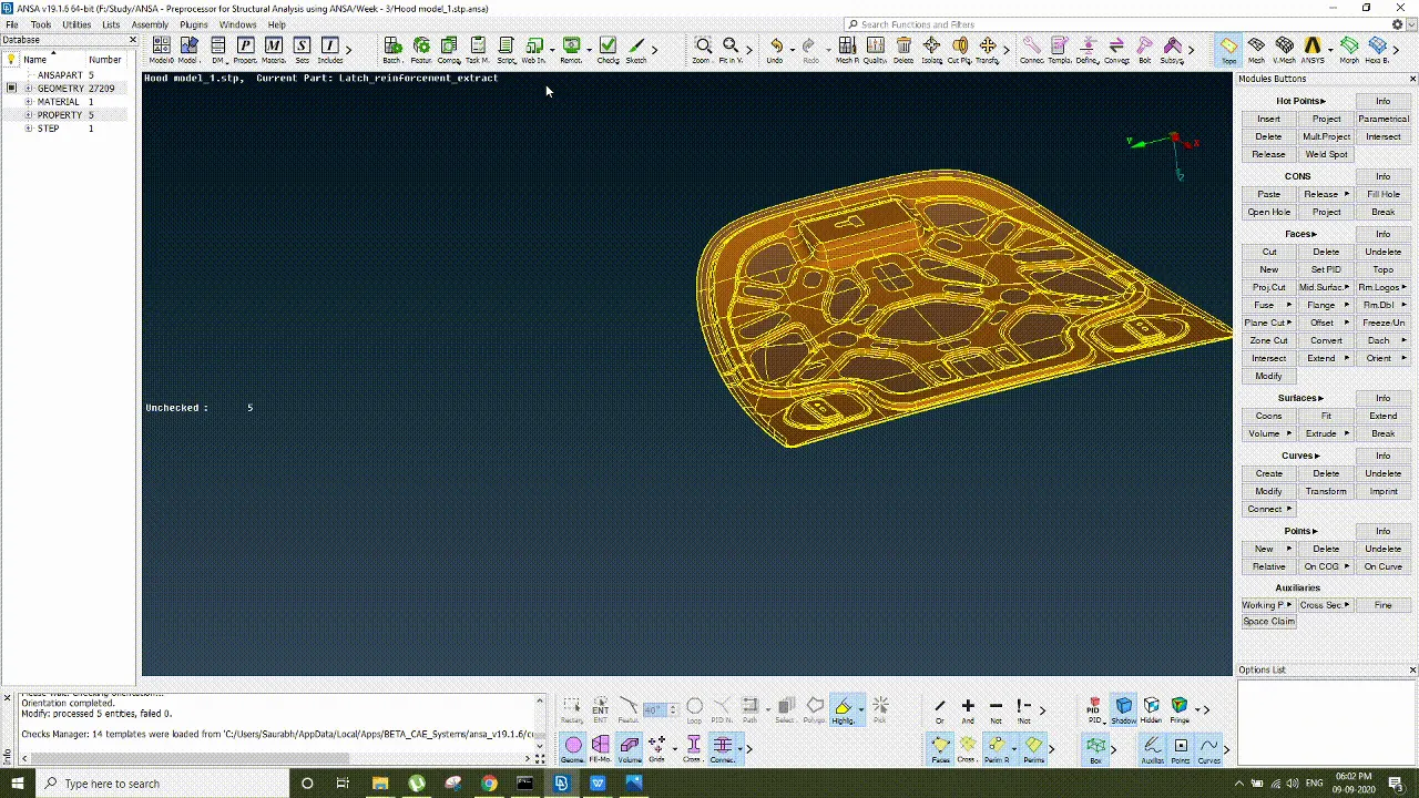
After the cad design of the product the design may look normal but their will sometime lots of extra surfaces, lines, points hidden in cad file which is very hard for anyone to find out which latter could affect the mesh and our final analysis so geometry cleanup is very vital step for the CAE engineer in a bid to get good results. We can do it in ANSA by following way.
2-D part and mid-surface:-
As the geometry is sheet-metal part which have same thickness so it can be considered as 2 dimensional part in order to simplify the geometry in can be converted into 2-D part by generating mid surface.
2-D elements are used when two of the dimensions are very large in comparison to the third dimension.
- Element shape : Quad, tria
- Additional data from user : Remaining dimension i.e. thickness
- Element type : Thin shell, plate, membrane, plane stress, plane strain, axi-symmetric solid etc.
- Practical applications : Sheet metal parts, plastic components like instrument panel etc.
Quite often the geometry of thin walled 3D structures, as shown in the image below, is simplified to a geometric model with lower dimensionality. This is typically called a mid-surface model. The midsurface model is then meshed with 2-D elements. Thus, there is no need for a detailed volume mesh as the thickness of the geometry is virtually assigned to the 2-D elements. Mathematically, the element thickness (specified by the user) is assigned with half in the + Z direction (element top) and the other half in the – Z direction (element bottom).
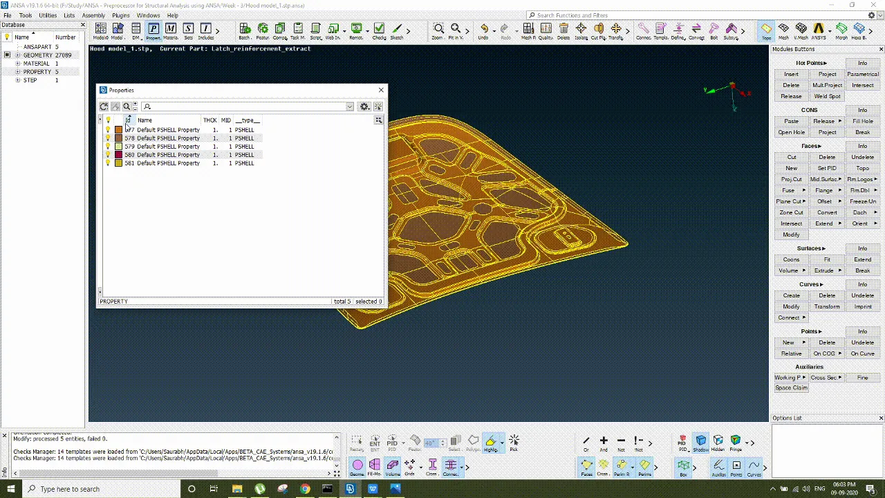
Once geometry cleanup is completed (e.g. surfaces areas stitched together — no unwanted free surface edges inside the geometry), meshing is next.
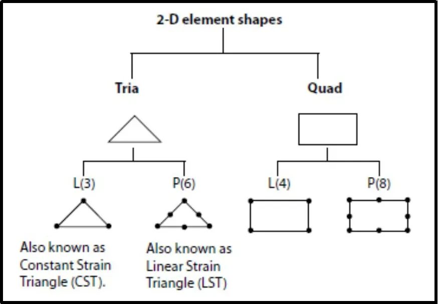
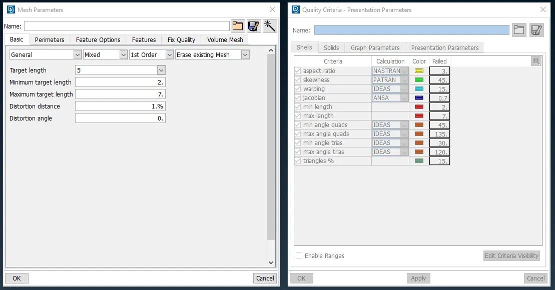
Before meshing, we have to set mesh quality criteria in in ANSA in order to achieve mesh as per requirement such as average required length and limits for the lengths like maximum permissible length and minimum permissible length. There are also some factor that we have to consider in mesh quality criteria, to generate proper mesh flow.
[1] Skewness
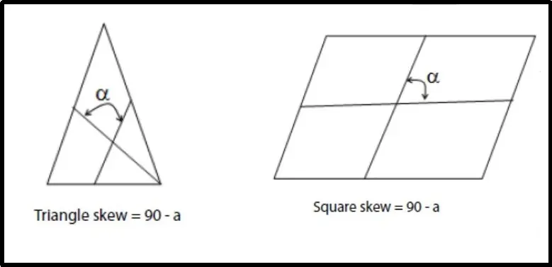
Skew in trias is calculated by finding the minimum angle between the vector from each node to the opposing mid-side and the vector between the two adjacent mid-sides at each node of the element. Ninety degrees minus the minimum angle found is reported. Skewin quads is calculated by finding the minimum angle between two lines joining opposite mid-sides of the element. Ninety degrees minus the minimum angle found is reported. The skew check is performed in the same fashion on all faces of three-dimensional elements.
Skew :
Ideal value = 0 (Acceptable < 450)
- Skew for quadrilateral element = 900 minus the minimum angle between the two
- lines joining the opposite mid-sides of the element (α).
- Skew for triangular element = 900 minus the minimum angle between the lines from each node to the opposing mid-side and between the two adjacent mid-sides at each node of the element.
[2] Aspect Ratio
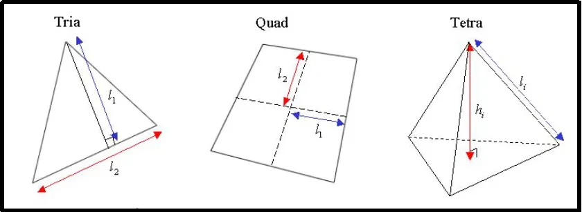
Aspect ratio in two-dimensional elements is calculated by dividing the maximum length side of An element by the minimum length side of the element. The aspect ratio check is performed in the same fashion on all faces of three-dimensional elements.
Aspect = maximum element edge length / minimum element edge length
Ideal value = 1 (Acceptable < 5).
[3] Warpage
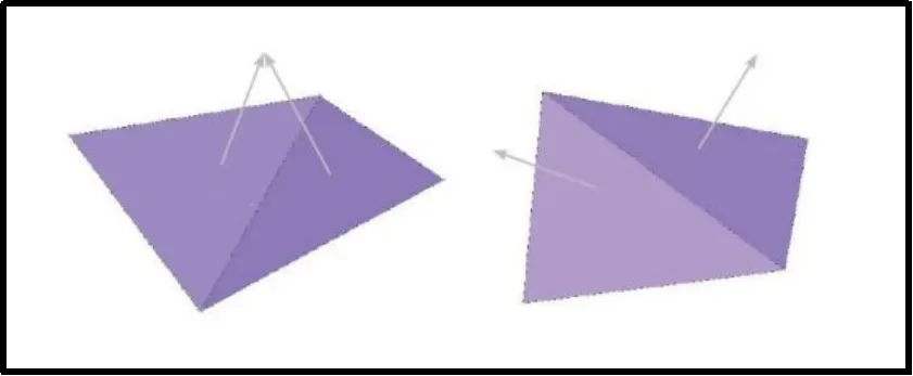
Warpage in two-dimensional elements is calculated by splitting a quad into two trias and finding the angle between the two planes which the trias form. The quad is then split again, this time using the opposite corners and forming the second set of trias. The angle between the two planes which the trias form is then found. The maximum angle found between the planes is the warpage of the element. Warpage in three-dimensional elements is performed in the same fashion on all faces of the element.
Warp angle: warp angle is the out of plane angle
Ideal value = 00 (Acceptable < 100 ).
Warp angle is not applicable for triangular elements.
It is defined as the angle between the normals to two planes formed by splitting the quad element along the diagonals. The maximum angle of the two possible angles is reported as the warp angle.
[4] Jacobian:
Ideal value = 1.0 (Acceptable > 0.6 )
In simple terms, the jacobian is a scale factor arising because of the transformation of the coordinate system. Elements are transformed from the global coordinates to local coordinates (defined at the centroid of every element), for faster analysis times.
[5] Minimum element length :
This is a very important check for crash analysis (time step calculations). It is also applied in general to check for the minimum feature length captured and the presence of any zero length element.
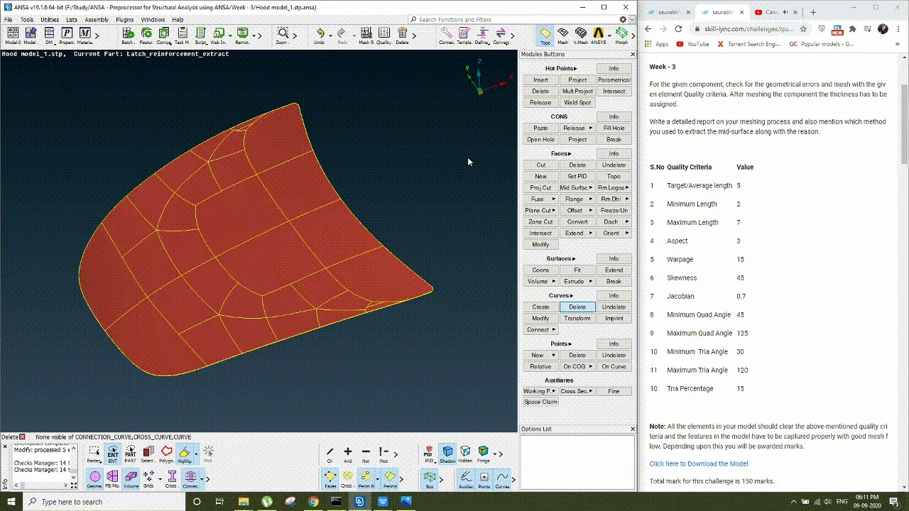
Setting mesh quality Criteria :-
After understanding about mesh quality criteria we set it in the ANSA in following way.
Auto symmetry :-
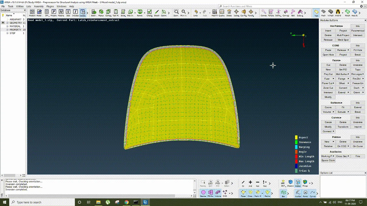
Now, to simplify the meshing and to save time we will find symmetrical part, if their we will break it in 2 part so we have to mesh only half side exactly as depicted in below gif file. And then we will remove unnecessary lines which dividing the surface also follow this step to simplify the other geometries also.
Manual symmetry :-
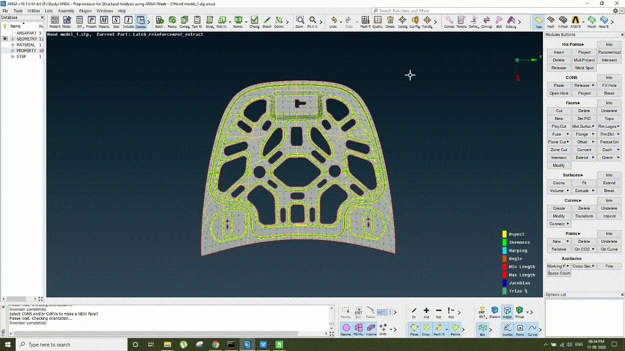
In other case, the geometry is not fully symmetrical so we will remove the other similar surfaces and mirror them latter.
Defeaturing :-
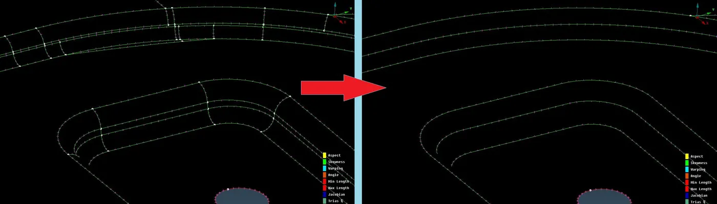
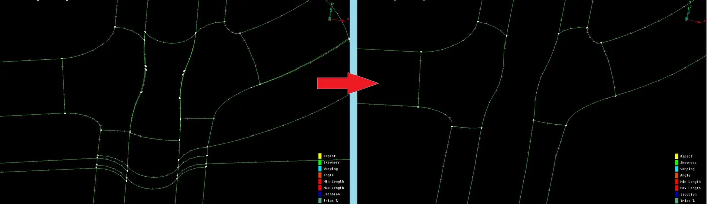
In defeaturing we will remove the surface which can disrupt the mesh flow, cons which have minimum distace less than 2mm and unecessary lines After defeaturing geometry will look like this.
Washer :-
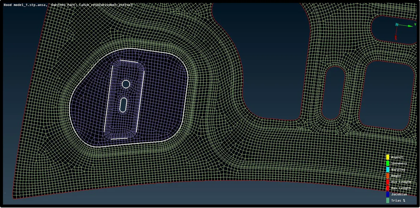
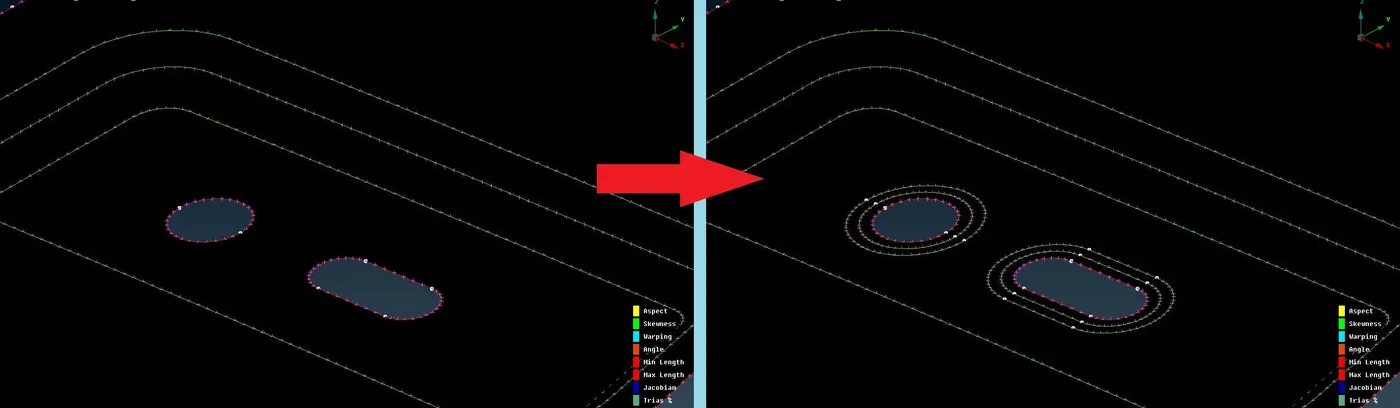
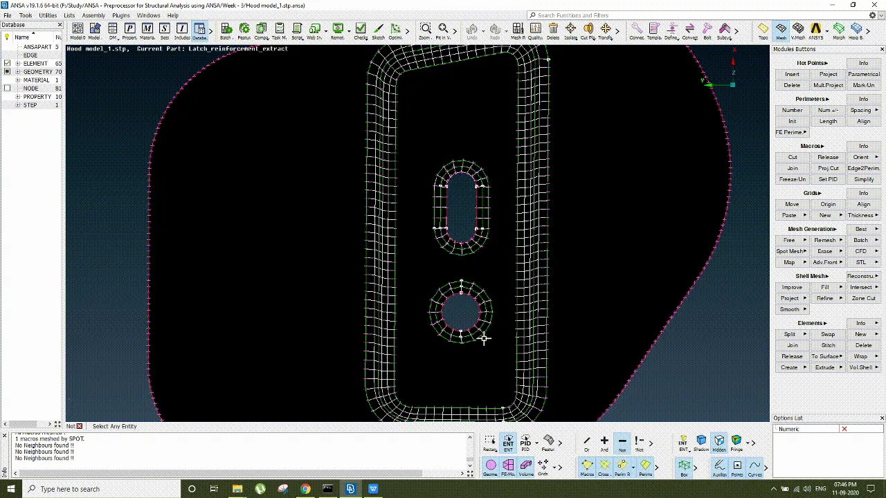
Now, one last task we are going to perform before meshing is that creating washer around the hole or circular section to avoide tria elements on the boundry using zone cut.
Meshing :-
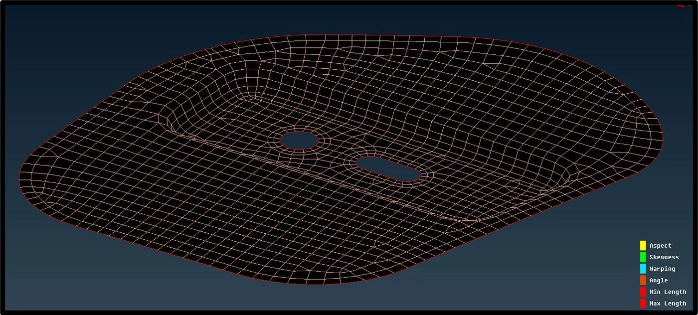
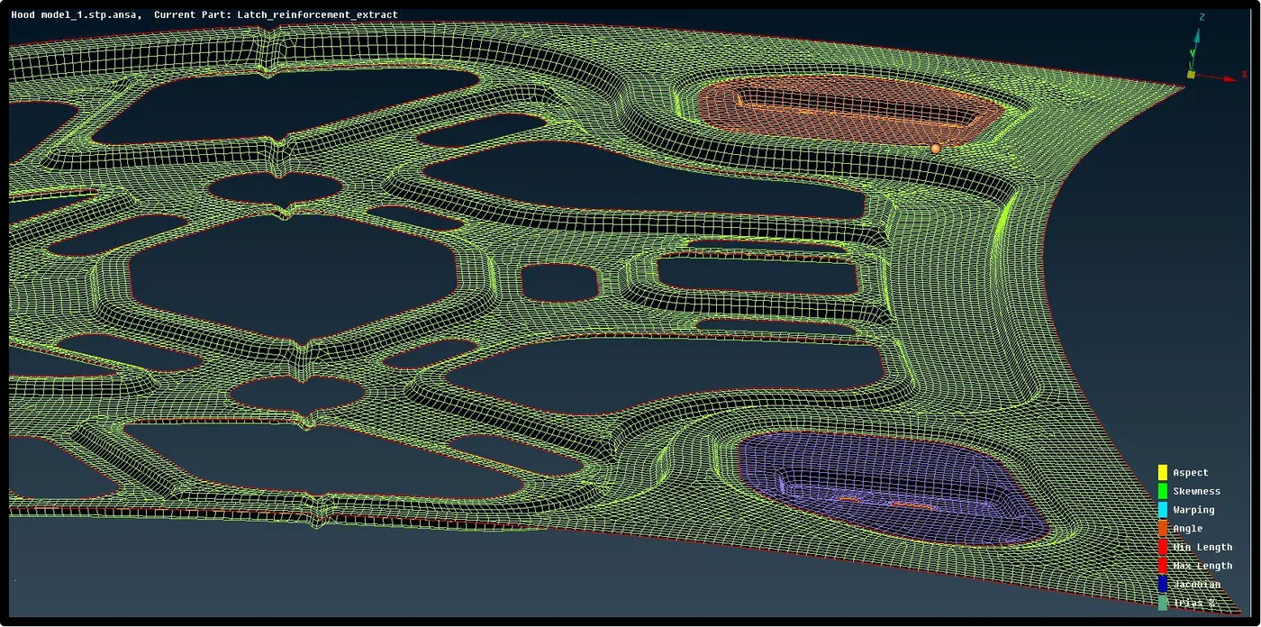
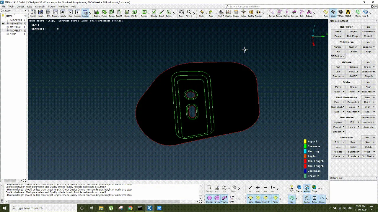
At last, we are now ready to generate mesh in ANSA.first go to mesh section → mesh generation → best.
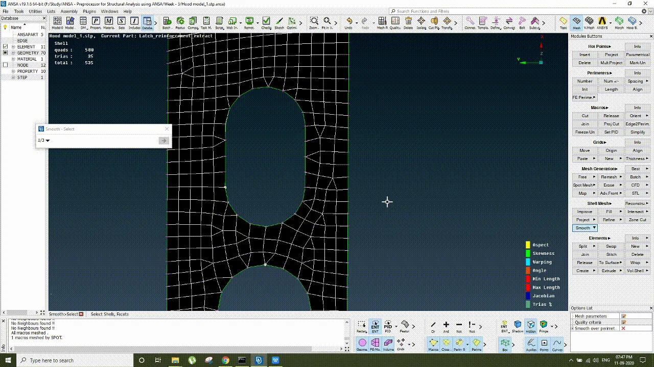
And then Reconstruct it from shell mesh section to reduce tria element and smooth it from same section.
first we mesh washer around holes and then we mesh other surfaces.
Manual mesh reconstruction:-
We the triangles facing each other or opposing each other in mesh flow by splitting the elements.
Defeaturing at boundry:-
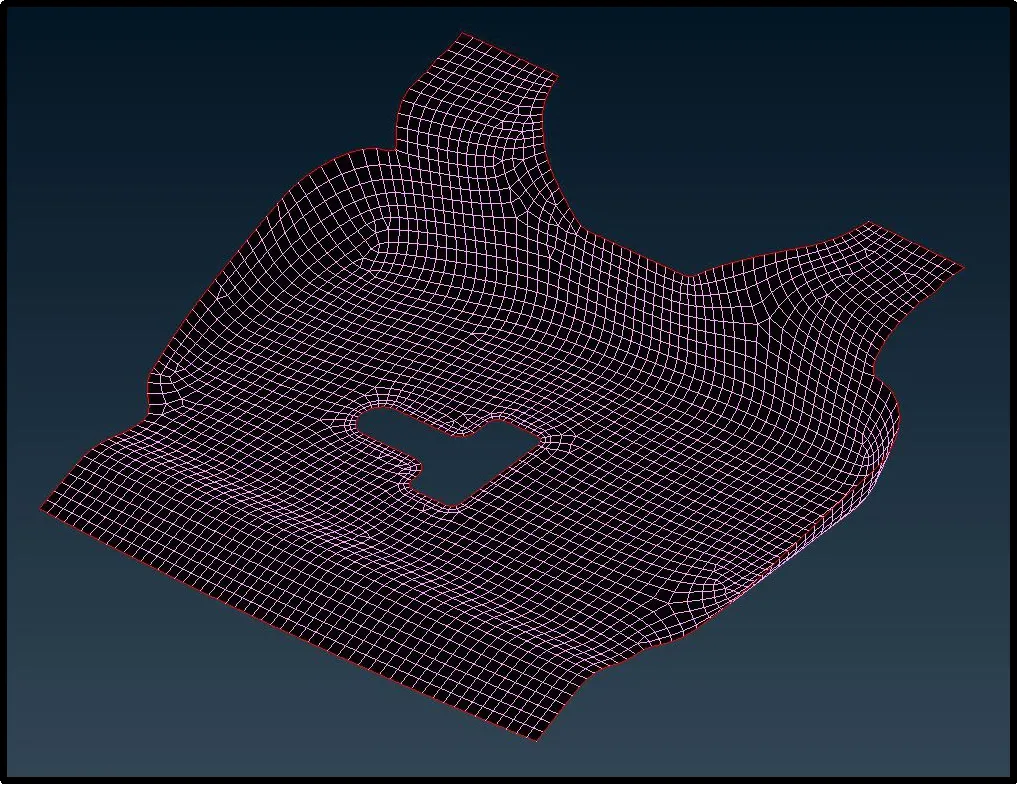
Same way we will mesh all other parts.
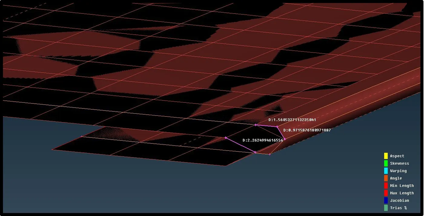
Before we see meshing of symmetric part, there is surface is bent at the border which can generate mesh element less than 2 mm. That break our mesh quality criteria. We can avoid that problem following way:-
Result:- 0.9 mm elements are converted into 2.26 mm element to fit the mesh quality criteria.
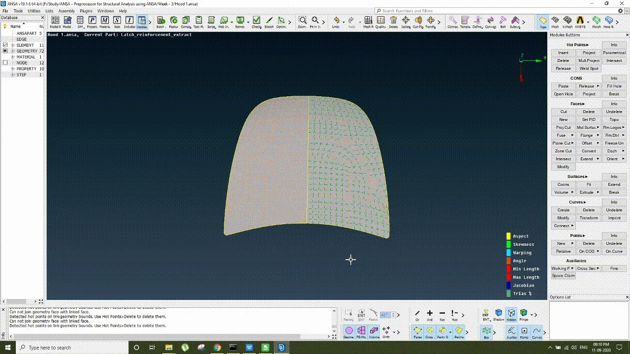
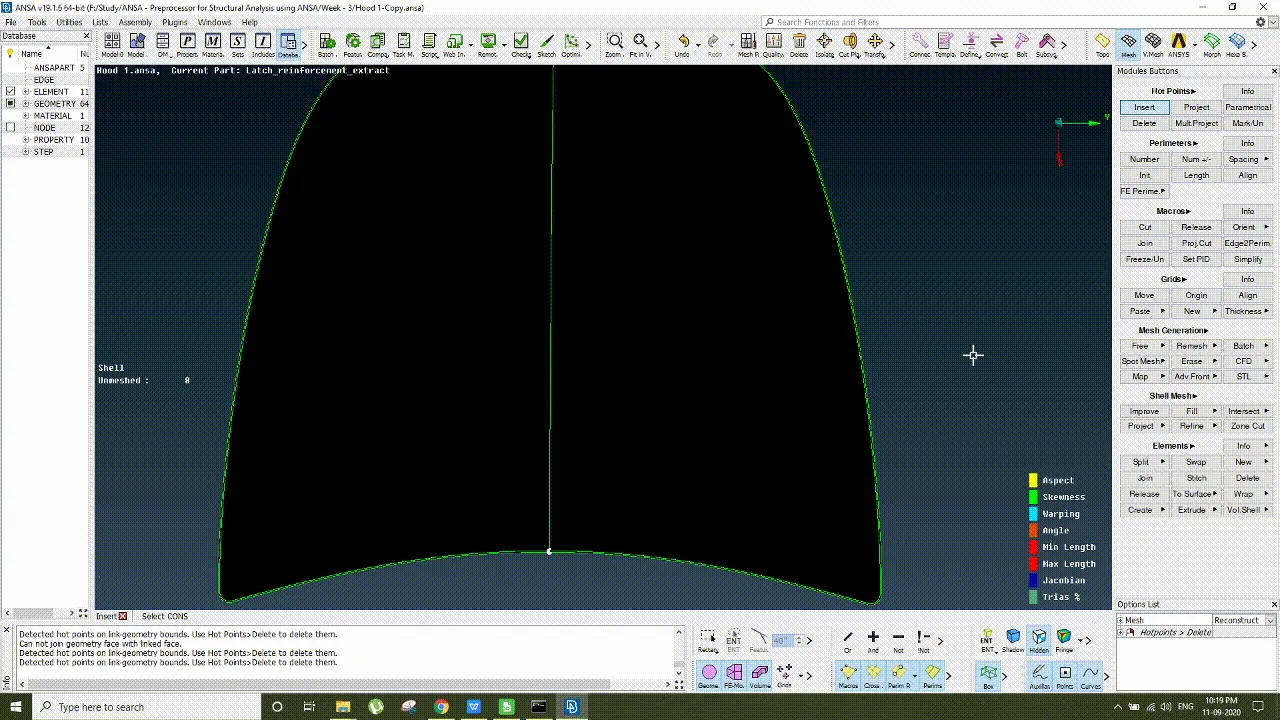
Auto symmetry Meshing:-
Next, meshing to symmetrical object can be done following way:-
Manual symmetry Meshing:-
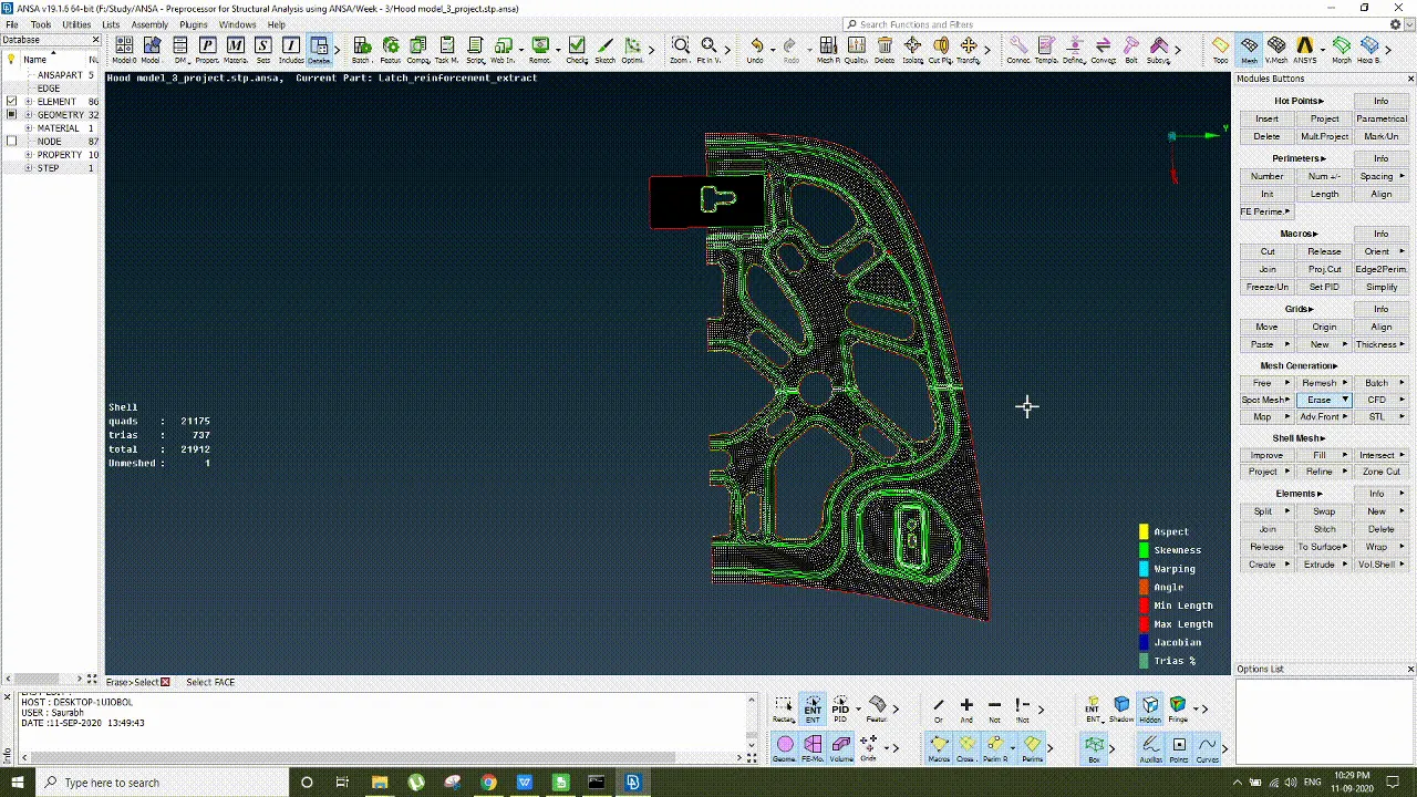
Second, way to adopt symmetry mesh technique is to mirror the mesh using transformation feature.
Delete Joins:-
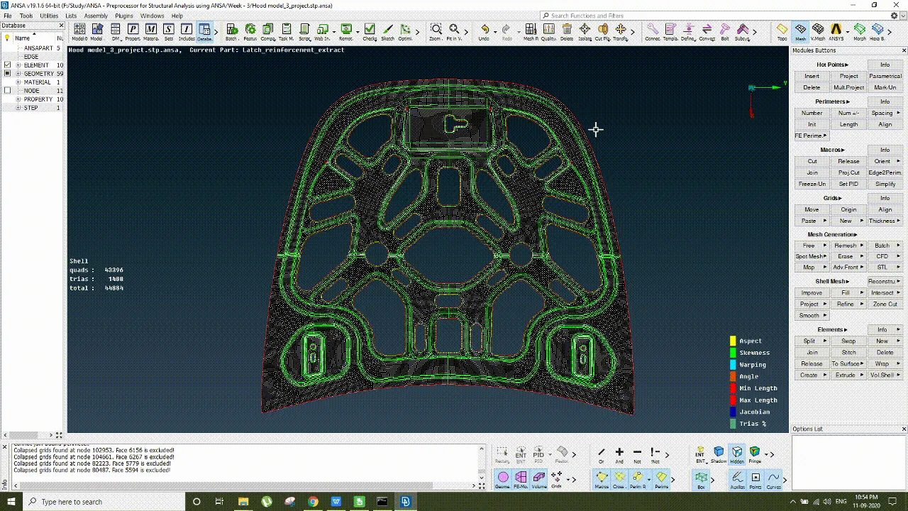
After generation of mesh, even small changes in joins can change the mesh flow through geometry, which can mess up our generated mesh structure, in a bid to avoid that in join option list change mesh instruction from reconstruct to keep.
Release Mesh :-
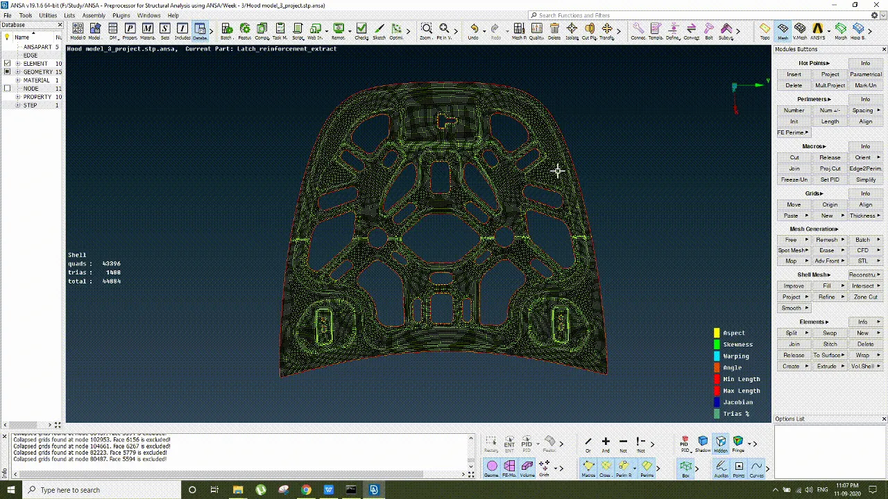
Even after removing all the joins the mesh keep attache to the geometry so if we manipulate the faces it will change accordingly. Also to export it we have to send mesh file separately. To achieve that, extract elements using release option in elements. But after this operation one cannot make any changes to the mesh.
Conclusion:-
- Understood the panels and controls in ANSA meshing software.
- Studied the concept of 2 d meshing on the uniform thickness part also generation of mid-surface.
- Importance of the geometry cleanup and defeaturing before the generation of mesh is noted.
- Quality criteria, its parameters as well as assumptions is been cleared through theory and practice in ANSA.
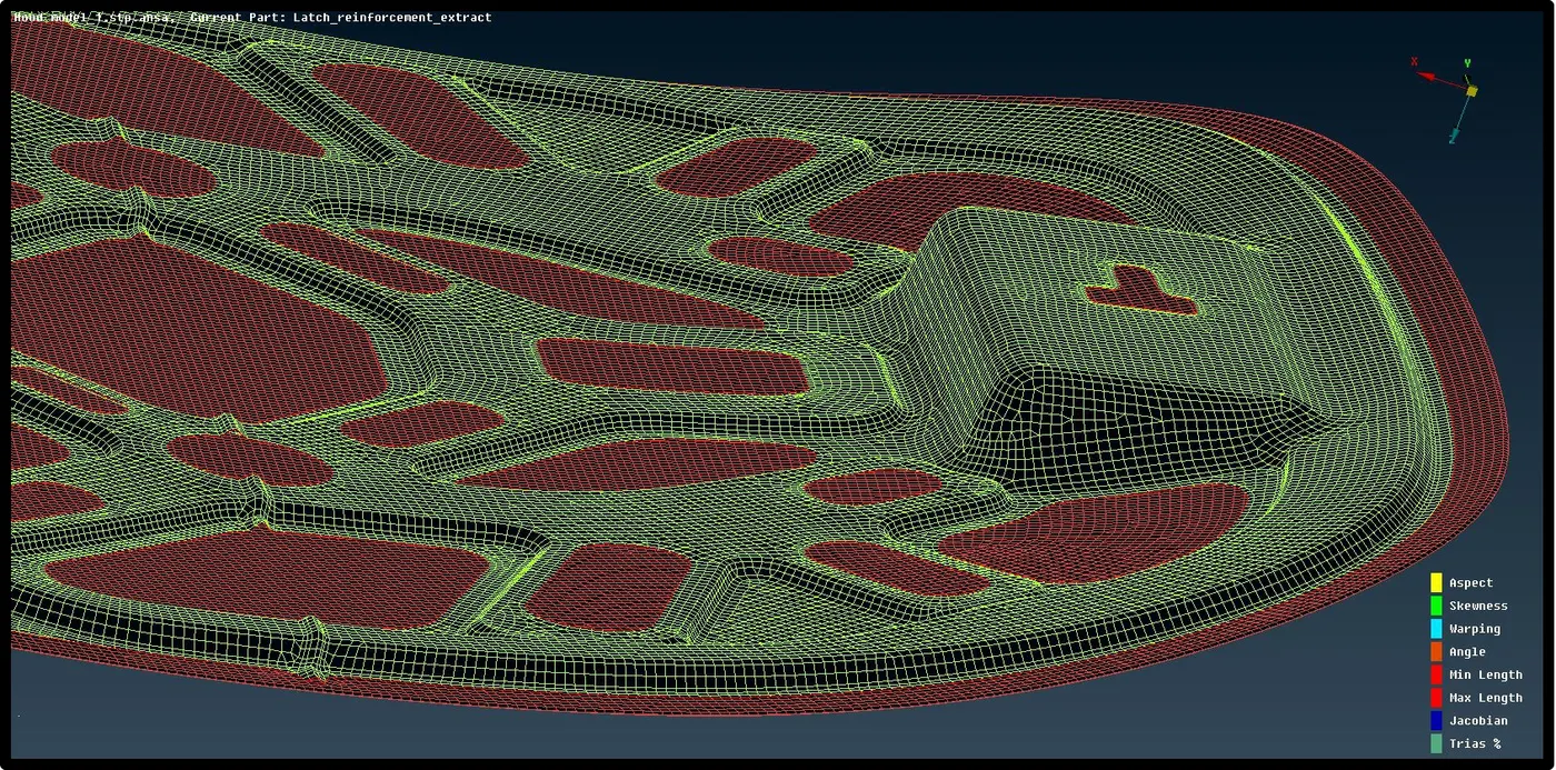
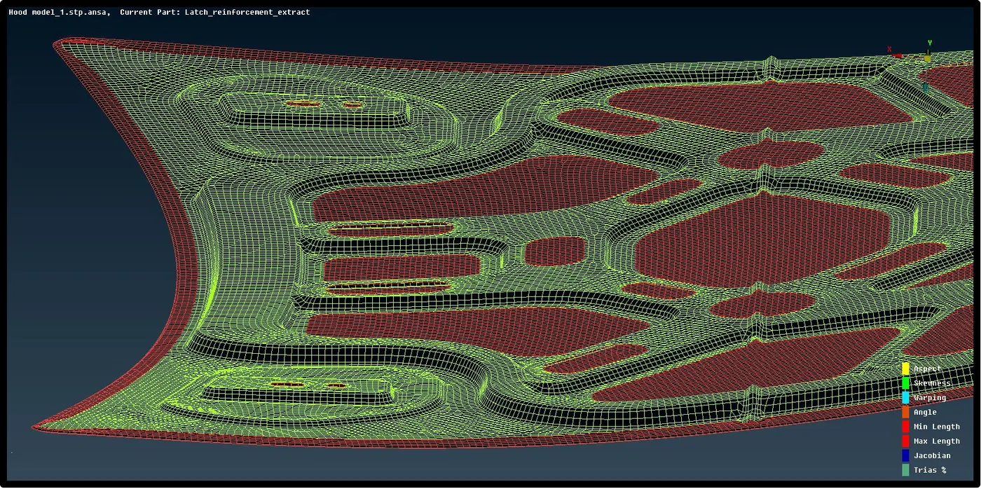
- Successfully generated mesh on 2D geometry and extracted by releasing it from geometry.
Result :-