Mesh the Bonnet Model with quality criteria using ANSA
AIM: To Create meshing for the vehicle hood by cleaning geometry errors and making midsurface using ANSA.
KEYWORDS: Topo, Cons, CFD, Nastran, mesh, etc.,
SOFTWARE: Ansa
OBJECTIVE:
1. To check the number of parts included in the given assembly.
2. To clean up the geometry for each part and do topo.
3. Creating midsurface for each part and again check for geometry clean up.
4. Applying mesh-like general, CFD, and Standard any one of this.
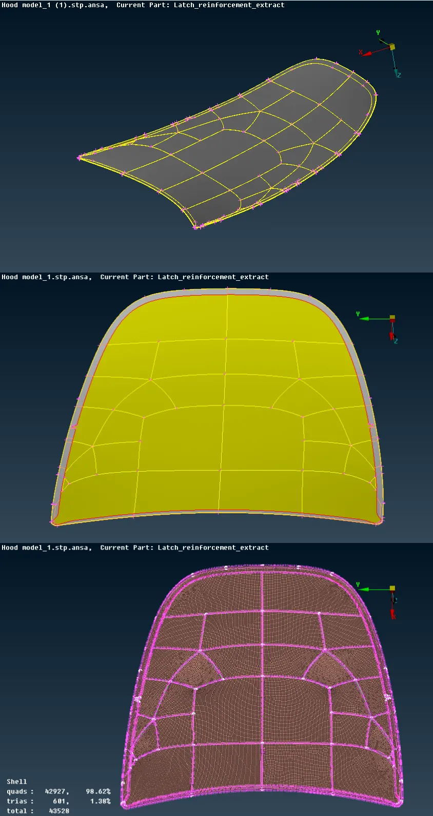
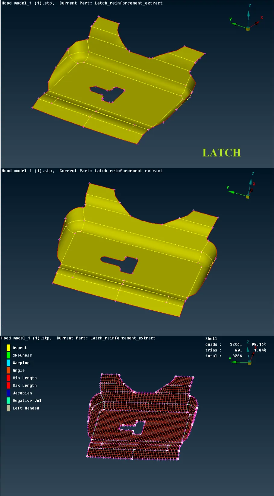
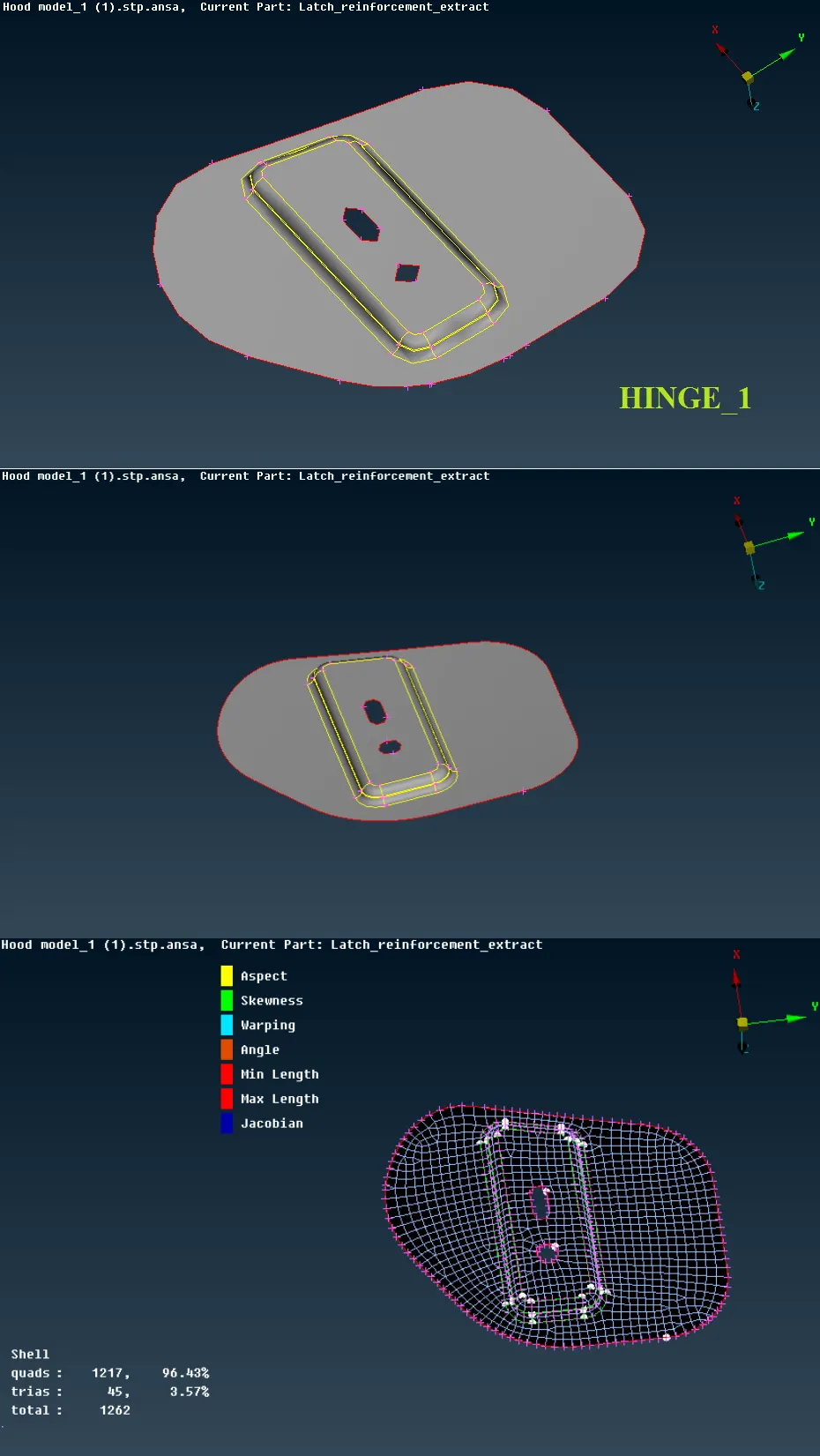
5. Here, CFD mesh as applied part wise and reduced trias near to the hole and features applied.
6. After doing the mesh for all parts, assign the thickness for the meshed assembly (Draw shell as solid).
INTRODUCTION:
ANSA is a computer-aided engineering tool for Finite Element Analysis and CFD Analysis widely used in the automotive industry. It is developed by BETA CAE Systems. ANSA maintains the association between CAD geometry and the FE mesh. This means that the FE meshes are better representations of their geometric parents. Also, it is easy to maintain and update any changes in the geometry by simply reworking the updated area instead of recreating the FE from scratch. It carries several proprietary algorithms for meshing suitable for both CFD and structural models. ANSA was initially standing for 'Automatic net generation for structural analysis', but the software has gone beyond that very quickly.
In ANSA software there certain kinds of tools used for geometry clean up, meshing, and different types of solvers to define certain problems. Initially, the CAD model should import into the software and check for geometry any error found! there are certain types of errors like triple cons, single cons, unchecked faces, convex cons, etc., These errors can fix automatically and also manually.
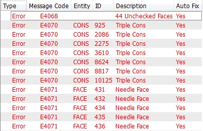
Before reading any CAD data into ANSA you can specify some settings concerning the application of Topology (the connectivity of neighboring Faces), and the Resolution (the appearance of geometrical entities on the screen). These settings should correspond to the dimensions, level of detail and tolerances of the CAD file to be input. Here, the CAD model as Hood which contain 5 parts.
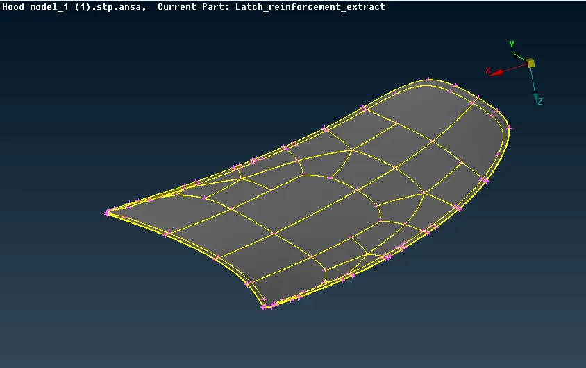
For each part we need to do the geometry clean-up, topo, midsurface, and meshing. After done all the meshing in each part as per the quality criteria we need to assign the thickness as Draw shell as Solid.
Quality Criteria:
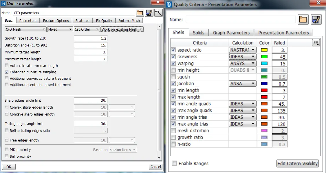
Part 1 - Inner constraint:
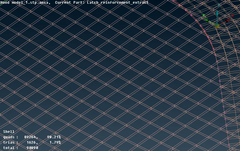
In order to mesh the component the very first stage is to clean up the geometry and do topo if any mis-joint occurs. By using geometry cleanup, we can do it in Auto fix mode or manually. After doing all the geometry clean up start created the midsurface. The offset of this part is 0.375, after the midsurface again check for the geometry clean up except single cons. Apply mesh for the created mid_suraface, the mesh used as CFD for better accuracy and as per the quality criteria as shown in the above figure. The steps to do topo, midsurface, and meshed area for all parts are shown in the below figures respectively. In the vertical image, the first image defines the part without topo and geometry cleanup. The second image defines the part with topo, midsurface, and geometry clean up. The third image defines meshed parts respectively for all 4 parts. There is no off elements present in all meshed parts, the number of quads and trias is available in the meshed part itself.
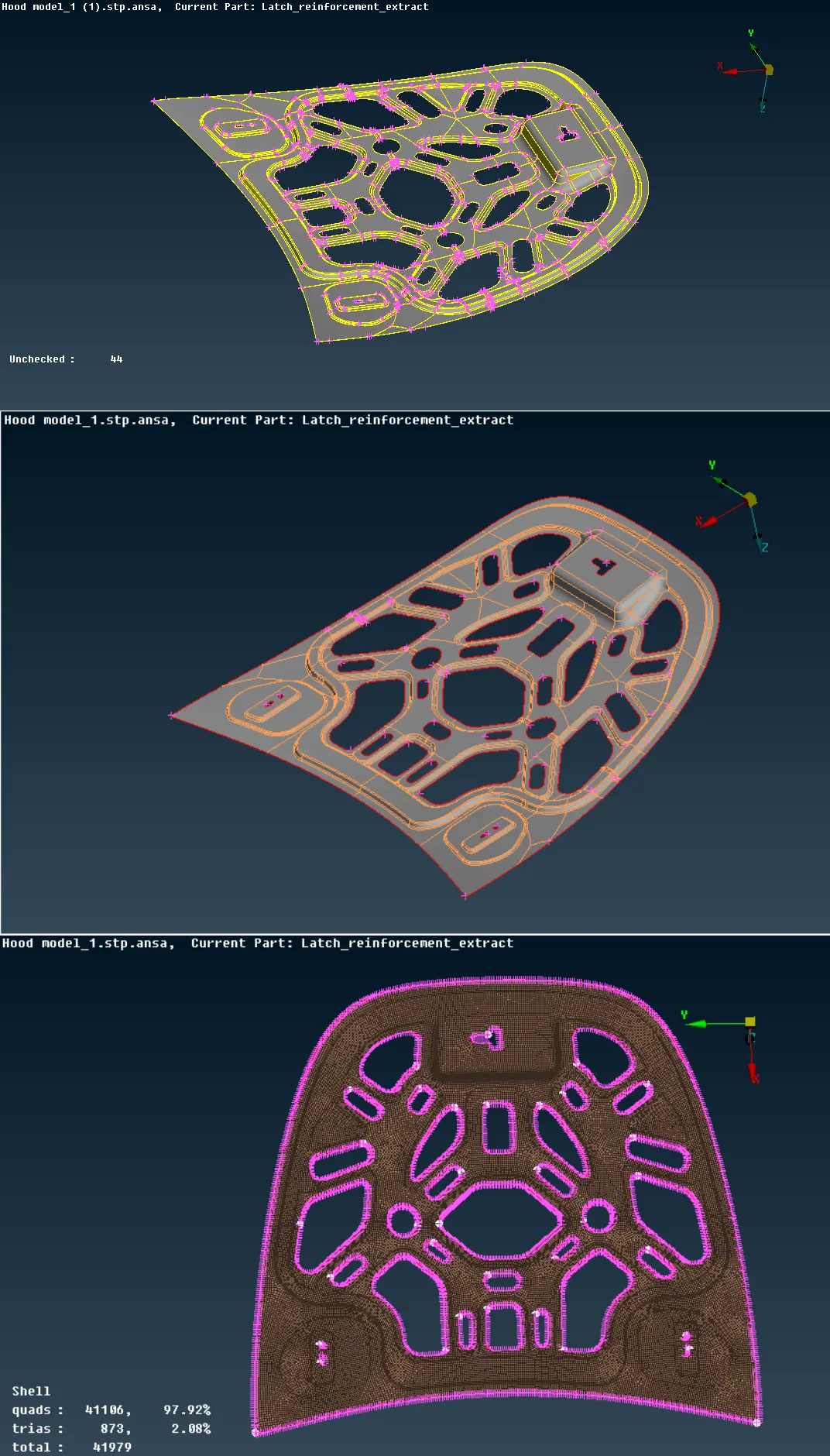
Part 2 - Outer constraint:
Part 3 - Latch:
Part 4 - Hinge (2 No's)*
RESULT:
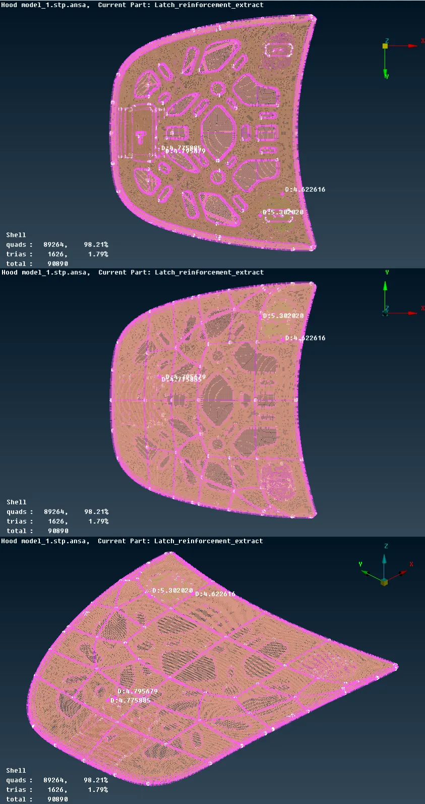
The above figure shows the complete assembly of the meshed Hood parts as per the quality criteria and also assigned the thickness for the assembly as Draw Shell as Solid. The thickness of the assigned assembly as shown in below figure,
CONCLUSION:
- In this model completed the geometry clean up, topo and midsurface. After all the process started applying the mesh for all parts as per the quality criteria.
- The Geometry cleanup can eliminated by auto fix and some error can be fixed by manually.
- The midsurface can be created by auto mode for complex parts and manually for simple parts.
- After all the midsurface created, stared doing mesh for all parts. The mesh used as CFD for better accuracy and flow.
- After completed all the mesh for all individual parts as assembled and assign thickness as "Draw shell as solid".