Week 3 - 2D meshing for sheet metal
AIM – we are given a model(car hood) having 5 components. We have to mesh all the components of this model in the best way possible and our final aim is to achieve a good meshed structure of component.
PROCEDURE
- First we import the design in ANSA.
- Then we check for geometrical errors in all the components of the model by using Tools>Checks>Geometry. If any error pops up, we have to fix it.
- After this we need to create the mid-surface for each component of the given model using either offset or doing automatically mid-surfacing.
- We then provide each component with a new property by Topo>Faces>Set PID in order to provide properties to components.
- After providing PIDs we have to work on each component mid-surface and we will have to mesh it.
- In order to mesh, we need to set the quality criterions required for this project. The requirements of the quality criterion are provided to us.
- For providing quality component to the model go to Quality criteria (or F11), there set up few number of properties under shell tab. After it, go to the presentation parameters tab, keep some functions on there.
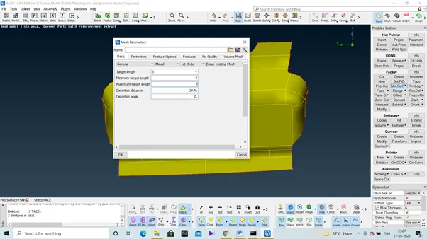
- After it go to mesh parameters to provide length parameters there, types of element, etc.
- Now coming to meshing, first the complicated regions must be meshed then move to simpler regions.
Below is the mid-surface of a component (latch).
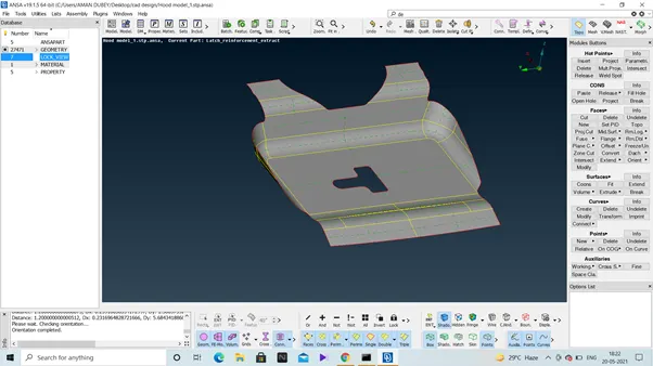
Similarly we have created mid surface for various other parts of the models, next thing is assigning of the property ids to these mid surfaces.
Below is the screenshot of the mid-surface of hinge parts of the model in which the PIDs is given.
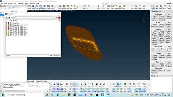
Creating a mid-surface using offset, for that go to Topo>Faces>offset, then we have to select the surface and provide the distance there.
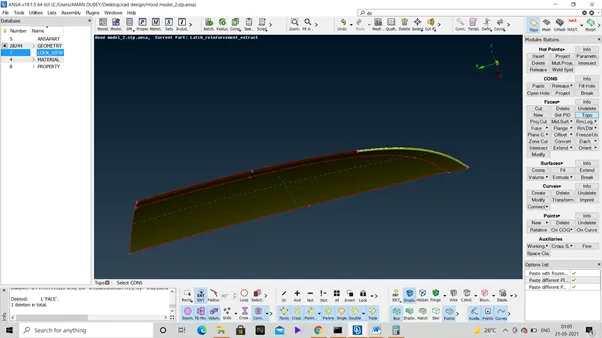
While dealing with the curved parts of a component, we normally see that the mid-surface is not aligned with the parent body, now in such a case we need to make some changes in the parent body and for that we can use fine option. Refer below screenshot.
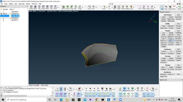
In order to make the whole mid-surface aligned to the parent body in one attempt, then go to Mesh>Perimeters>length. Assign the length and click ok.

We can also create the mid surface in one go by using Topo>Faces>Midsurface. We need to provide offset link by distance as shown below
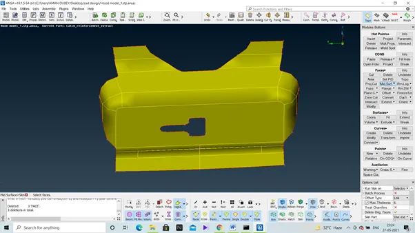
After the confirmation we will have a mid-surface of the whole component (Latch) in one go as shown below
Then we have to apply the quality criterion using quality index
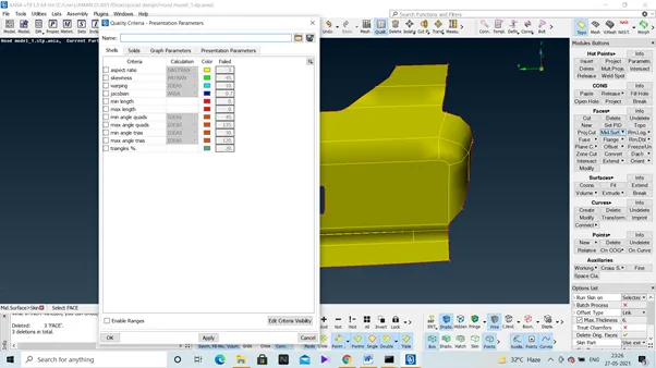
After it, we assign the element properties in the Mesh parameters tab under utilities.
Then we are good to proceed ahead with meshing, it’s better to assign PIDs too to the mid-surfaces as shown below:
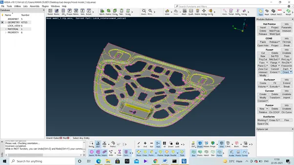
Assign property id to each of the respective mid surfaces of the different components, as below
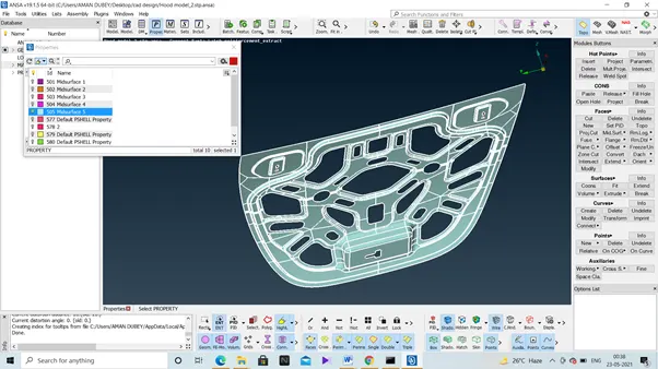
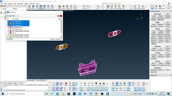
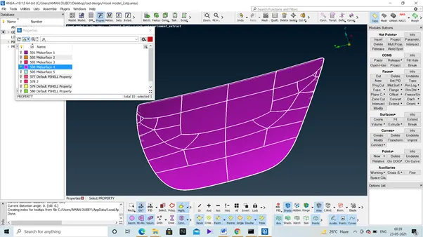
Next thing is meshing
Join, where the criterion is failing for sure due to very less elemental size, we use the option of join there, sort of defeaturing.
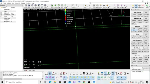
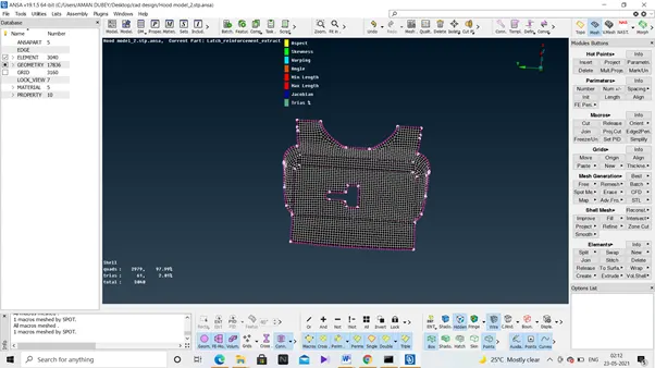
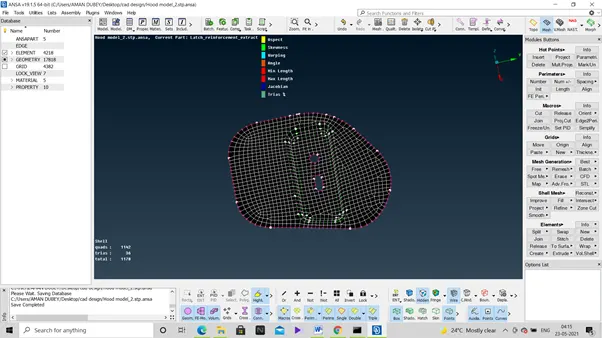
Problems- at around corners we have lots of failed elements, in order to correct these, we need to defeature our model to some extents. One of the good way is to use the option of Cut in macros under mesh tab.
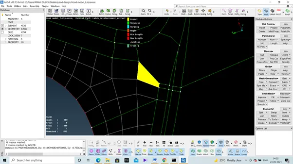
Solution-
Defeaturing is required at the curved corners as the elements fails for various quality reasons like skewness, warping, jacobian.
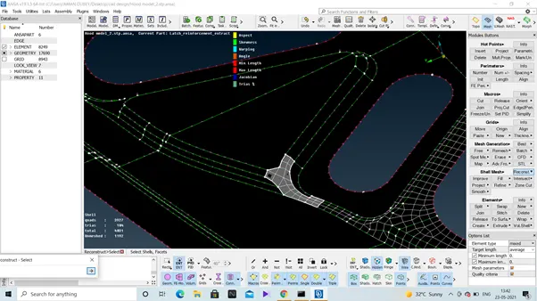
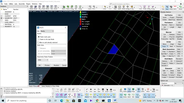
Use paste option to remove some trias like in below situation
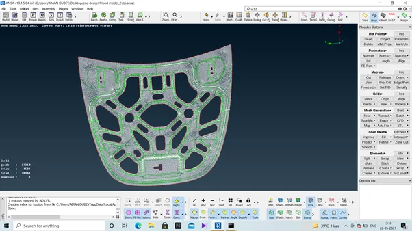
Problem - while meshing the exterior surface of hood, around the curved edges lots of elements are getting failed cause of minimum length of elements.
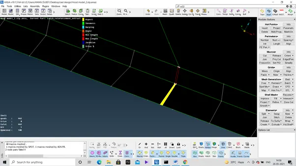
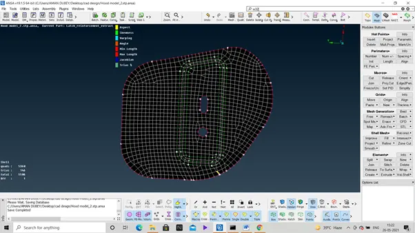
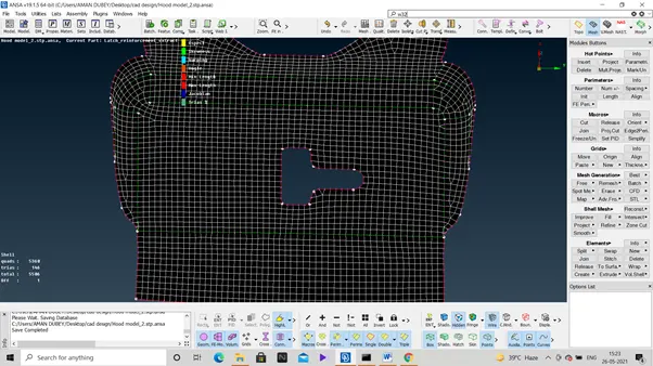
Solution - I know it is tedious but it is the only solution that came into my mind with the limited knowledge of the tool I currently have, I use the cut option and made a sort of parallel curve w.r.t. the boundaries (defeaturing) and then deleted the previous boundaries. Below is the screenshot provided for showing the same.
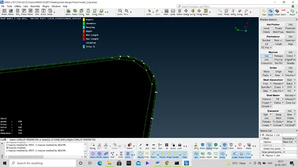
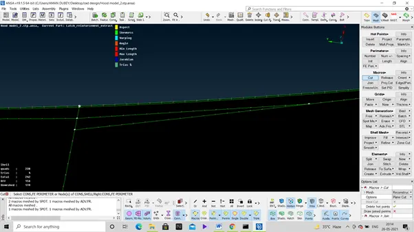
Removing all the extra lines, now we can mesh without getting the elements failed cause of minimum length restriction as the defeaturing essentially was done to increase the length of the elements.
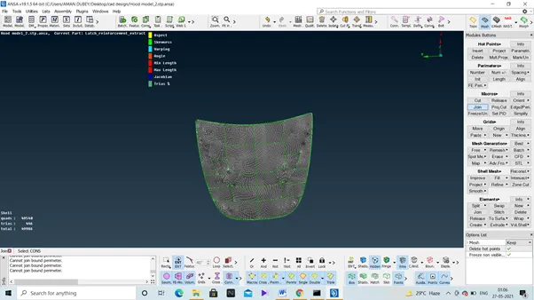
As we join the internal boundaries , number of trias will keep on decreasing as a non divided region facilitates more better meshing by creating quads elements.
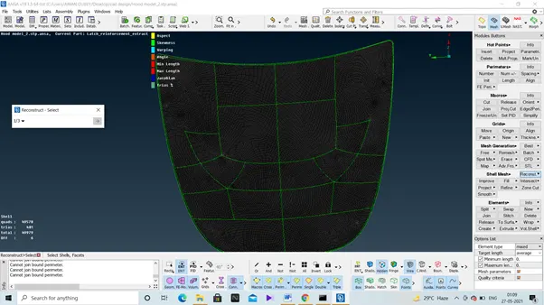
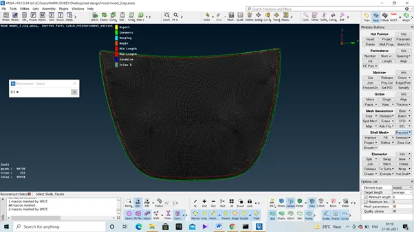
All meshing surfacing overlapping each other
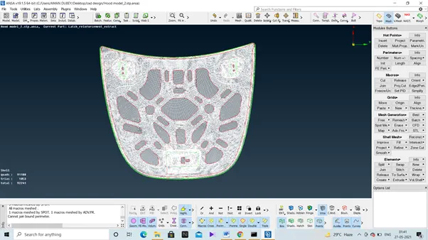
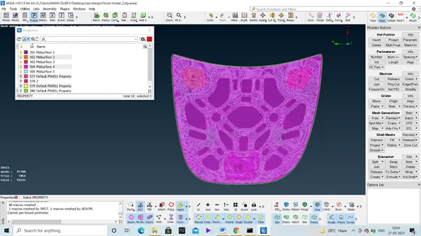
As it is the requirement to provide the thickness to the meshed mid surface, so below is the meshed mid surface with thickness too. For this we can choose the option of ‘Draw shell as solid’ and apply.
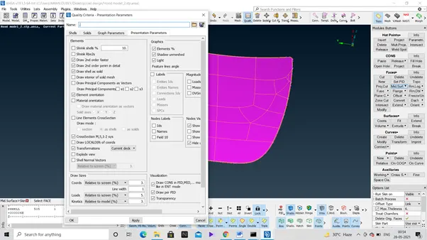
By going to properties, we can provide the thickness to the mid surfaces equal to the parent body in the property id of that particular component. Refer below-
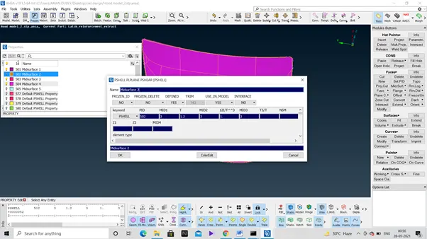
Below is the screenshot for the meshed mid surface with the thickness.
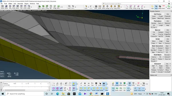
Final objective, every component in this assembly is well meshed without any errors with trias element in under 2% and rest quad elements. Below is the repersentation of solid mesh of model components.

Well learing graph for me was strictly an increasing type while doing this assignment and the problems I across with teaches me various ways to tackle them.
Conclusion - I am able to succesfully mesh the car hood model as per the requirement, following all the quality criteria.