Week 3 - 2D meshing for Sheet metal
AIM :
To extract the Midsurface and Mesh the given Hood component by following the specified quality criteria using ANSA.
SOFTWARE TOOL USED :
ANSA Version 22.1.0
OBJECTIVE:
- Perform the pre-processing techniques i.e. Geometry clean-up, Mid surface extraction, and 2D shell meshing for the hood component of a car.
- After meshing following the given element quality criteria, assign the thickness to the Car Hood.
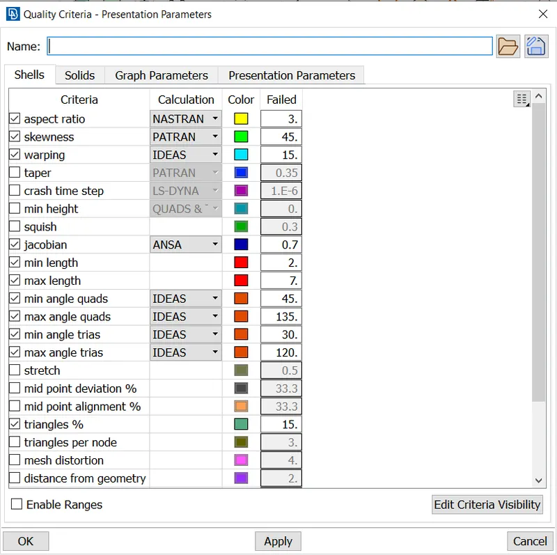
Given Quality Criteria :-
|
S.No |
Quality Criteria |
Value |
|
1 |
Target/Average length |
5 |
|
2 |
Minimum Length |
2 |
|
3 |
Maximum Length |
7 |
|
4 |
Aspect |
3 |
|
5 |
Warpage |
15 |
|
6 |
Skewness |
45 |
|
7 |
Jacobian |
0.7 |
|
8 |
Minimum Quad Angle |
45 |
|
9 |
Maximum Quad Angle |
135 |
|
10 |
Minimum Tria Angle |
30 |
|
11 |
Maximum Tria Angle |
120 |
|
10 |
Tria Percentage |
15 |
INTRODUCTION:
i. Computer-Aided Engineering (CAE) :
Computer-aided engineering (CAE) is the use of computer software to simulate performance in order to improve product designs or assist in the resolution of engineering problems for a wide range of industries. This includes simulation, validation, and optimization of products, processes, and manufacturing tools.
A typical CAE process comprises of Pre-processing, Solving, and Post-processing steps. In the pre-processing phase, engineers model the geometry (or a system representation) and the physical properties of the design, as well as the environment in the form of applied loads or constraints. Some of the Pre-processors are ANSA, Hyper mesh. Next, the model is solved using an appropriate mathematical formulation of the underlying physics. Some of the solvers are ABAQUS (for durability analysis), NVH (for noise, vibration, and harshness analysis), LS DYNA (for crash, safety, and impact analysis). In the post-processing phase, the results are presented to the engineer for review. Some of the Post-processing are METAPOST, HYPER VIEW.
ii. Automatic Net Generation for Structural Analysis (ANSA) :
ANSA is an advanced multidisciplinary CAE pre-processing tool that provides all the necessary functionality for full-model build-up, from CAD data to ready-to-run solver input file, in a single integrated environment.
ANSA is the user's preference due to its wide range of features and tools that meet their needs. The list of productive and versatile features is long and the alternative tasks and processes to be completed using them are countless.
iii. Engine Cover or Engine Hood :
The engine cover or Engine hood is the most eye-catching body component and an important opening piece to the body, which directly affects the overall performance and comfort. Front cover assembly not only plays an important role in air guiding but also protects the engine and surrounding pipeline accessories, meanwhile it can sufficiently avoid impact, corrosion, rainwater, and electric interference.
The following are the design consideration involved in the Design of the Engine Hood.
- Pedestrian Safety:
Pedestrian safety is always a factor involved in the design of the hood. This is achieved by the proper selection of material that can readily deform avoiding risk during impact, Providing embosses to inner panels, etc. This is one of the major factors for a vehicle to have better safety ratings.
b. Vehicle Quality:
This involves how best the hood can be designed to have better quality in terms of Torsional stiffness, dent resistance (Hailstone and stone chippings), Corrosion resistance better weight distribution, and noise attenuation.
c. Occupant Safety:
The design consideration must include the impact caused due to Frontal Crash Collapse. Such a scenario is expected that the Hood maintains its Integrity with hinges and also retains any loosed components from Engine Compartments.
d. Styling:
Better Surface quality (A-class Surface Finishing), Tight radii on hemmed panel edges & low strain between curved regions of the inner and outer panel.
e. Manufacturability:
The design should be always considered for manufacturability e.g., Embossing on the inner Panel should have sufficient draft angles provided for the Punching tool to flow in and flow out. Any Design should be studied for Manufacturability in order to produce it.
PROCEDURE:
Step 01 : Importing Geometry
- The initial step is to import the geometry into ANSA Software.
File → open → select the file → open (Or we can drag and drop the file into ANSA)
Step 02 : Geometry cleanup
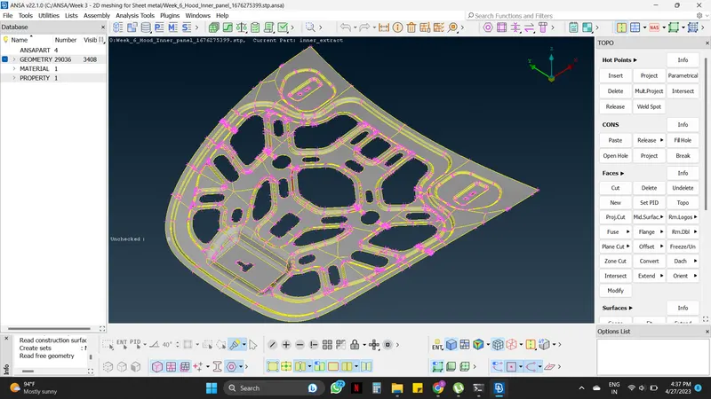
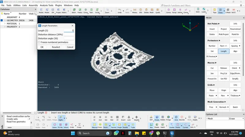
Cons resolution: We have to do the resolution of the con to check the actual shape of the cones in the geometry. There are two tools for that. One is the 'Fine' option in the Topo module under Auxiliaries. The other one is the 'Length' tool from the Mesh module under Perimeters. The 'Length' tool will help to do this in a single step when compared with the fine tool.
Mesh module → Perimeters → Length → Perimeter/macros (do this for both) → select the whole surface → middle mouse click → give the value as 5 → apply
Connectivity correction: If there are surfaces without connection in the imported model (Single cons). Correction must be done before doing the mesh. The 'Topo' tool can be used to perform topology.
Topo module → Faces → Topo → select the whole surface at once → Apply (Middle mouse click).
After performing Topo, it is seen that all the single cons are converted into double cons(Yellow).
This is also can be fixed while performing a geometry check.
After performing Topo, all the single cons (red) will be converted to double cons (Yellow).
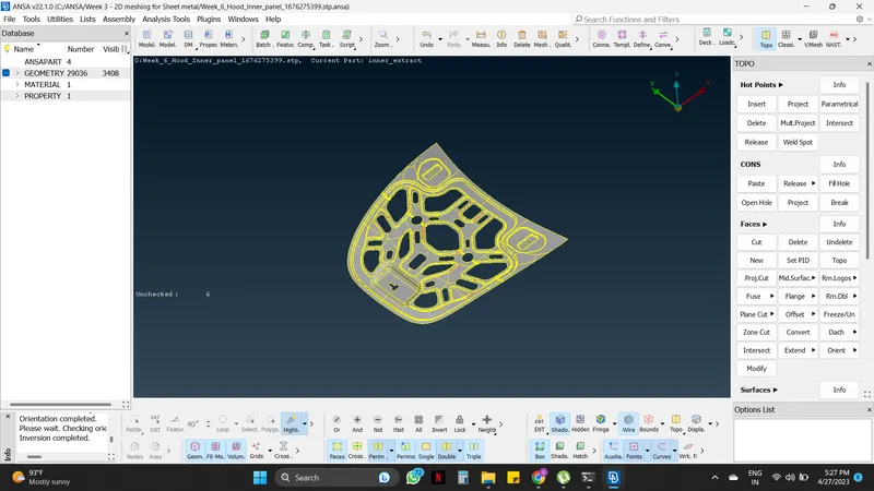
Orientation correction: It is observed that the given surface is with mixed yellow and grey color. This shows a mixed normal direction on the surface. So, to correct it as either yellow or grey on the outer surfaces to either gray(+ve) or yellow(-ve), preferably gray the tool, 'Orient' is used for this purpose.
Topo module → Faces → Orient → Choose select, Visible, and Auto appropriately
If cons correction is done properly, choosing the visible option will change the color of entire surfaces in one go.
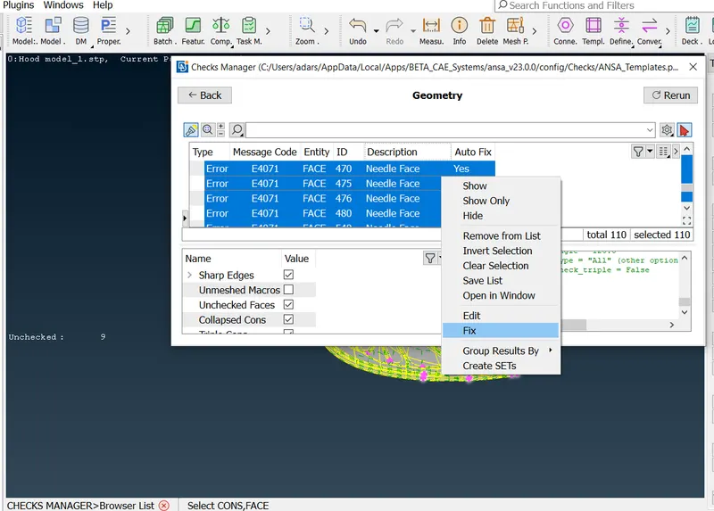
Geometry check: We need to check the geometry by using the 'geometry' tool to find and correct any other errors in the imported geometry.
Tool tab → Check → Geometry → Tick the single cone as well → Execute → If any errors pop up in red color select them at once → Right mouse click → Fix → If not fixed, try manually → Then execute the geometry check again, it will show No errors or warning exist.
After fixing all the errors manually the checks dialogue will appear as shown below.

Step 03 : Mid-surface generation
The hood is considered to be a sheet metal component (thickness <6 mm). So, midsurface must be extracted for meshing. For sheet metal, the thickness will be even throughout the surface. The initial step is to measure the thickness of the component by using the 'Measure' tool. Extract the mid surface and perform meshing.
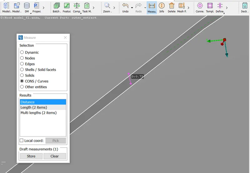
We know the given model (Hood) is a sheet metal component, there are two ways by which we can extract the mid surface. First is the automatic method known as 'skin' and the other is the manual method known as 'offset'.
TOPO module → Faces → Mid Surface → Skin → Select the entire component → Middle mouse click → Edit Areas window pops up (Ensure that one entire surface of the component is Red color, the other Green and thickness in Blue) (Red and green shouldn't touch each other), where we can edit miscolored surface by using faces option → Middle mouse click →Click on any of the Red/ Green surface → Skin offset value window pops up → Middle mouse click → Midsurface is generated.
Note: While using the Skin option for midsurfacing be sure to uncheck the 'Delete original faces' option in the options list. Else the parent component will be deleted upon generating the mid surface.
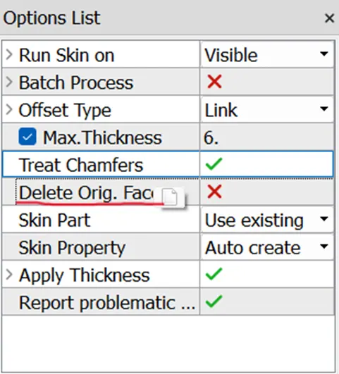
For large complex surfaces, Prefer to use the offset command instead of skin. Because, the RED, GREEN, and BLUE surface checking in the large complex surfaces would be time-consuming.
TOPO module → Faces → Offset → Select entire surfaces on one side of the component using the Feature selection tool → Give Offset value as '±Half of thickness' depending on the normal direction, change the property to 'Auto create' in the options list → Click OK → Select 'No' for Delete original faces window.
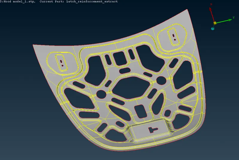
After getting the mid surface, the resolution of the cons must be done using the Length tool by giving the value as the Target element length ( Here it is 5).
Mesh module → Perimeters → Length → Perimeter/macros(do for both) → select the whole surface → middle mouse click → gave the value as target element size(It is 5) → apply
Step 04 : Setting up the Quality Criteria and Mesh parameter
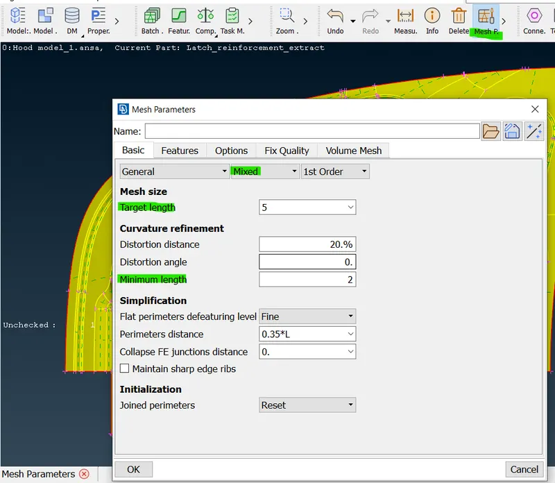
Setting up the quality criteria as well as mesh parameter is very important in every pre processing process. This will make the mesh proper as per the requiremnt. Here the parameters is given, as per the given data fill the dialogue box and apply to the component.
Utilities tab → Mesh Parameter → Set Element type: Mixed , target element size, minimum element size → Ok
Utilities tab → Quality Criteria → From Shell tab set 2D element qualities → Ok
Step 05 : Deleting the symmetric half of the Car Hood midsurface
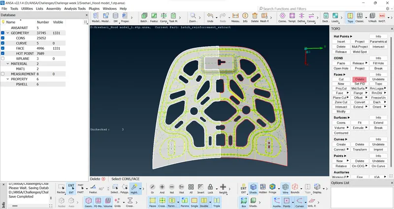
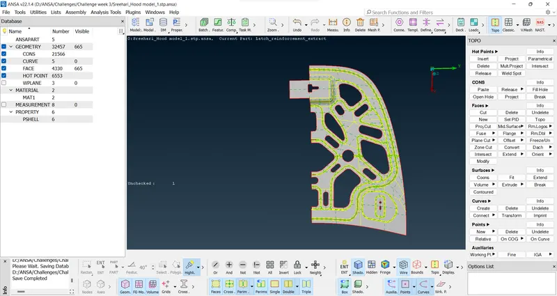
For components that are symmetric, it is better to trim the midsurface at the plane of symmetry and carry out meshing only on half portion of the component. Later the mesh on the other half can be generated by transforming this mesh along with the midsurface with respect to the plane of symmetry. This effectively reduces the mesh time and human effort. The same Transform tool is applicable for Hinge reinforcement extract as well.
TOPO module → Faces → Delete
Step 06 : Geometry cleanup on Midsurface
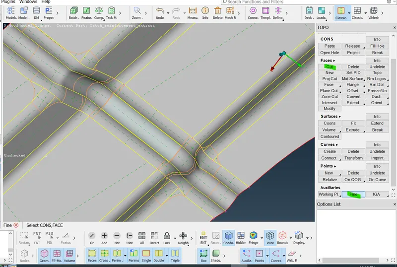
In this step, checking of the midsurface and suppression of the double cons which are very close to one another such that the distance between them falls below the minimum element length allowed is done. For this, the 'Cut' option in TOPO or Mesh module will be used. Precautions are taken to avoid sharp corners in construction lines by slightly changing them using the same cut option. Apart from these, the split command is also used to the surface into small square-like structures so that the mesh flow will be better.
TOPO module → Faces → Cut → Right click suppresses the double con → Left click cuts the surface.
The same option is available under the Mesh module as well.
Mesh module → Macros → Cut → Right click suppresses the double con → Left click cuts the surface.
The suppressed cons appear in orange color under the TOPO module while they won't be visible in the Mesh module.
Step 07 : Meshing
Generating the 2D mesh on the midsurface can be done with two approaches, the first is meshing the whole component at once by selecting the whole surface and the second is meshing small macro-regions for better mesh. For this, select the 'Best' option from the Mesh generation group in the mesh module. Select the surfaces to mesh, and the middle mouse click.
Mesh module → Mesh Generation → Best → Select the surfaces → Apply (Middle mouse click).
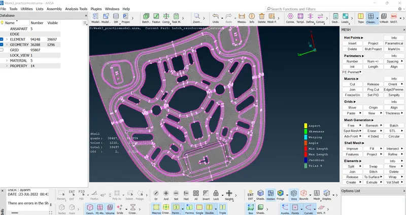
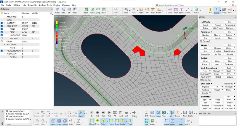
After Meshing there will be some errors that will not follow the quality criteria and will be seen in different colors. To make it proper and better mesh some commands must be used. Other commands like split, smooth, Num+/-, Swap, Join etc can be used to correct mesh flow.
Smooth : Mesh module → Shell Mesh → Smooth
Split : Mesh module → Elements → Split → Left click splits quads into trias and Right click acts as Swap edge and combines trias
Num+/- : Mesh module → Perimeters → Num+/-
Swap : Mesh module → Elements → Swap
Join : Mesh module → Elements → Join
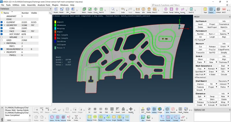
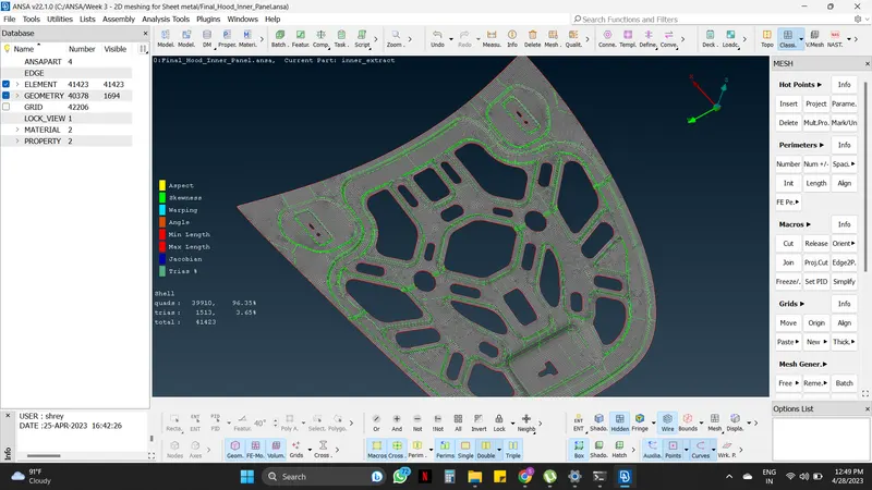
As shown in the above fig the Mesh is done with the help of different commands (explained above). Since the meshing is done of the half Car Hood Midsurface now the other half surface must be mirrored.
This is done by selecting the transform option, from utilities panel.
Utilities tab → Transform → Copy → Keeping the Entities option ticked select the whole half Car Hood component → Symmetry → Mirror 3 points plane (as shown in fig below).
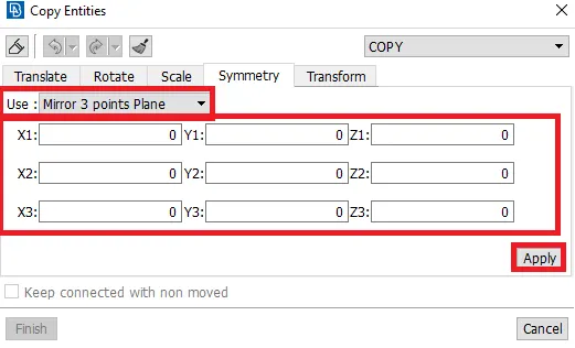
By selecting the three points randomly at the middle edge, the point's location with respect to the coordinate system will be entered automatically as shown in fig below.
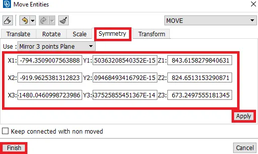
Click on Apply and then Finish the Approach. This will create the Meshed another half of the Car Hood.
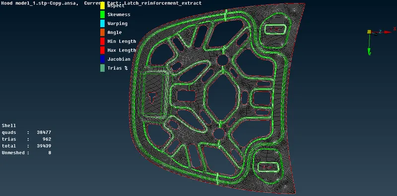
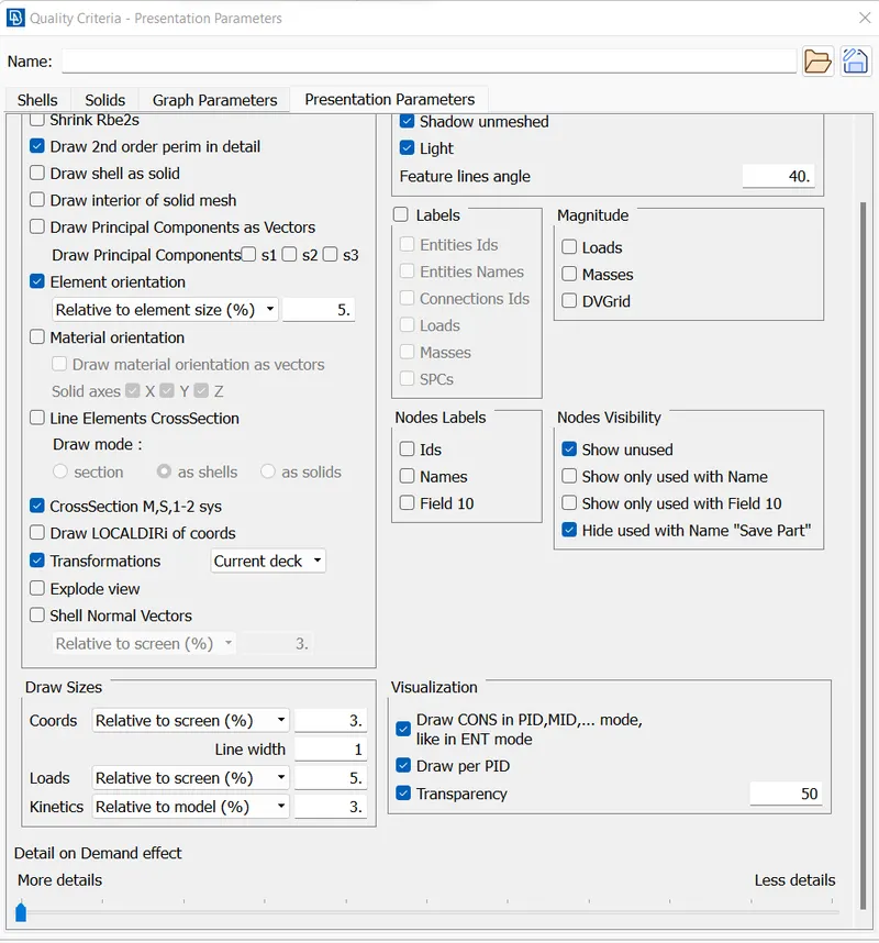
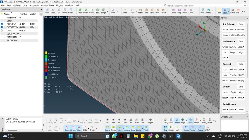
Here a properly meshed (as per the given quality criteria and meshing parameters) car hood Mid surface is created. Now thickness must be assigned to the mid-surface. To see the elements with respect to the thickness, an option named "Draw shells as solid" in the quality criteria panel must be enabled as shown in fig.
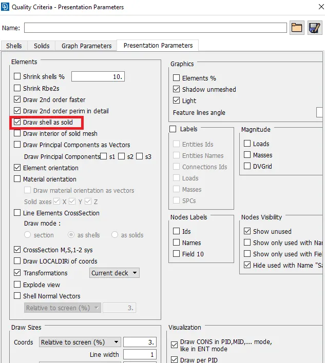
After enabling it, the elements with the assigned thickness appear as shown in fig below.
CONCLUSION :
- Extracted the mid-surface of the given Car hood model.
- Generated a 2D mesh on the components, based on the given quality criteria and assigned the thickness.
LEARNING OUTCOMES :
By doing this challenge, the following aspects can be learned:
- Basic tools in ANSA.
- Extracting mid-surface in ANSA.
- Generating a 2D mesh on the extracted mid-surface.
- Using mirror option to reflect.
- Assigning the thickness to the mid-surface.