Week 3 - 2D meshing for Sheet metal
Objective:-
The 2D meshing of Sheet metal as given Hood Inner Panel with the below-mentioned quality criteria and features.
|
S.No |
Quality Criteria |
Value |
|
1 |
Target/Average length |
5 |
|
2 |
Minimum Length |
2 |
|
3 |
Maximum Length |
7 |
|
4 |
Aspect |
3 |
|
5 |
Warpage |
15 |
|
6 |
Skewness |
45 |
|
7 |
Jacobian |
0.7 |
|
8 |
Minimum Quad Angle |
45 |
|
9 |
Maximum Quad Angle |
135 |
|
10 |
Minimum Tria Angle |
30 |
|
11 |
Maximum Tria Angle |
120 |
|
10 |
Tria Percentage |
15 |
CAD Model:-
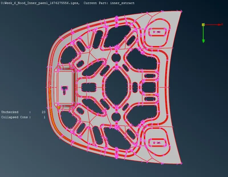
The Below-mentioned CAD model is taken for 2D meshing.
Procedures:-
- Open Ansa Software using Start->All Apps->Beta CAE Systems->Ansa Vxx.x.xx With Performance Mode 3 on Launch Screen
- Import CAD File Using File->Open. After importing it looks like the above image 1.
- Checking the CAD surface finish by Panning across the Model and removing Extra cons available in CAD Surface
- Giving Topology to model by using Faces->Topo in the Modules Manubar.
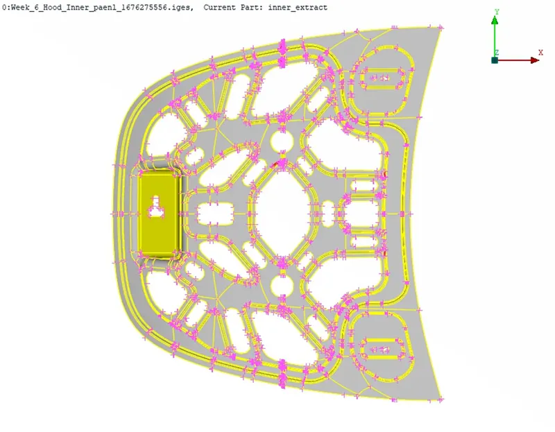
- Do the Geometry Clean-up Using the below steps.
- Checking any single cons and triple cons are generated across the model by Panning across the model
- If Single cons are available again give Topo to that area. if it converts to double coons is ok.
- If any Triple Cons are available in the model, remove them by using the below comments
- Release the cons by using the Cons->Release command in Modules Manubar and Select the cons with the left click of the Mouse.
- Removing the extra cons by deleting the extra Hot points available in the Area by using Hot Points->Delete.
- after that give Topo to that particular area by using Faces->Topo.
- If any sharp edges or cracks are available follow the below steps to get the Closed surfaces for generating mid-surface.
- Delete the Sharp edges or cracks using Faces->Delete a comment in the modules menubar.
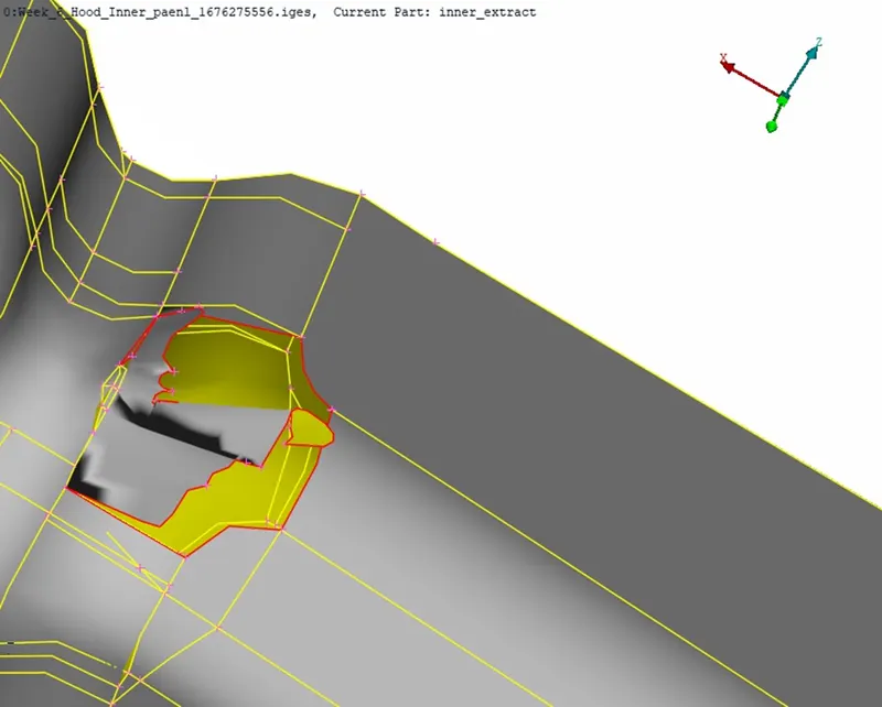
- and delete the faces which are not in the correct formation after will get an unfilled surface like the below image.
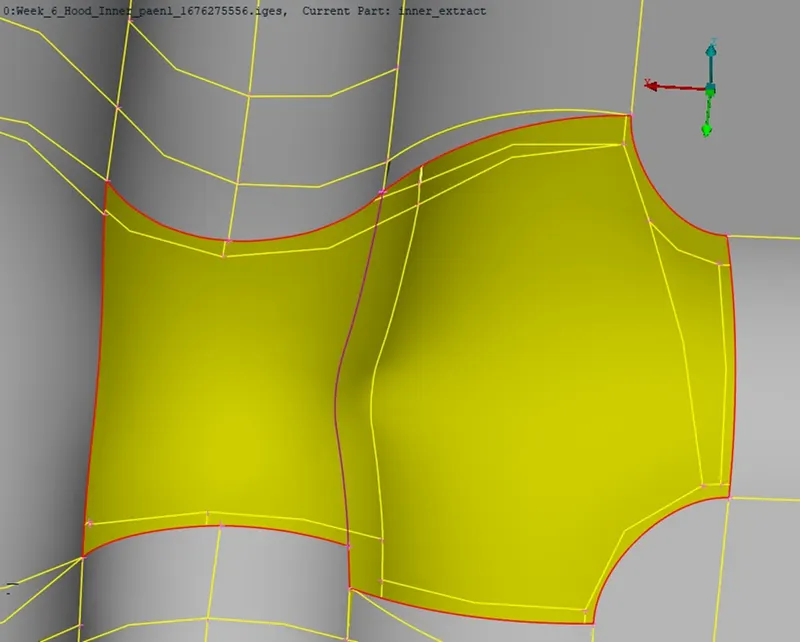
- using create cons as like opposite surfaces by using the Curves->Transform. select the con we want to copy with the left mouse click and complete the action with the middle mouse click. it highlights with vector and selects the first hot point near the vector and selects a second hot point opposite side to finish the action with the middle mouse click.
- We get the generated curve on the cracked face with purple color as shown in the above image.
- Create a new face using Faces->New. it opens a pop-up window that selects Fitted Comment among the other options. then select the respective cons and complete the selection with the middle mouse click. It creates a new face as shown in the below image.
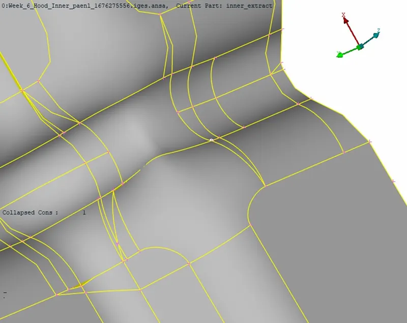
- After using the Fine tool to increase the CAD resolution by using Auxiliaries->Fine Comment and selecting the faces or coons by using the left mouse click as shown in the below images.
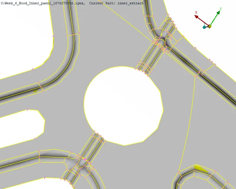
- And the same selection option for all areas by Panning across the model. After increasing the resolution, the model looks like the below image.
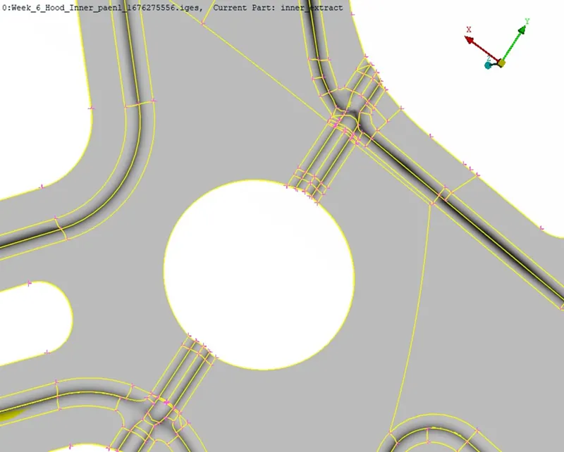
- Improve the CAD surface orientation by using Faces->Orient->Visible. It changes as a high ratio orientation is available in actual CAD Surfaces.
- Before Orientation
- After Orientation
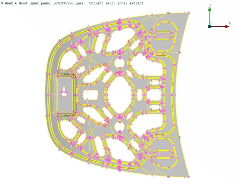
- After Orientation Check the Geometry by using Checks->Geometry in Tool Manubar. It opens the Checks Manager Pop-Up Window.
- In that ensure the below comments are enabled.
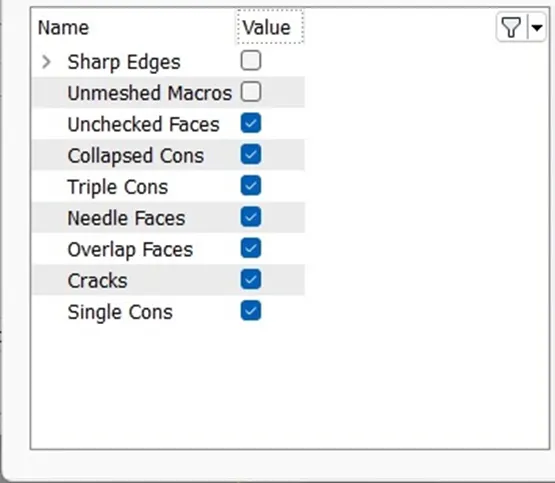
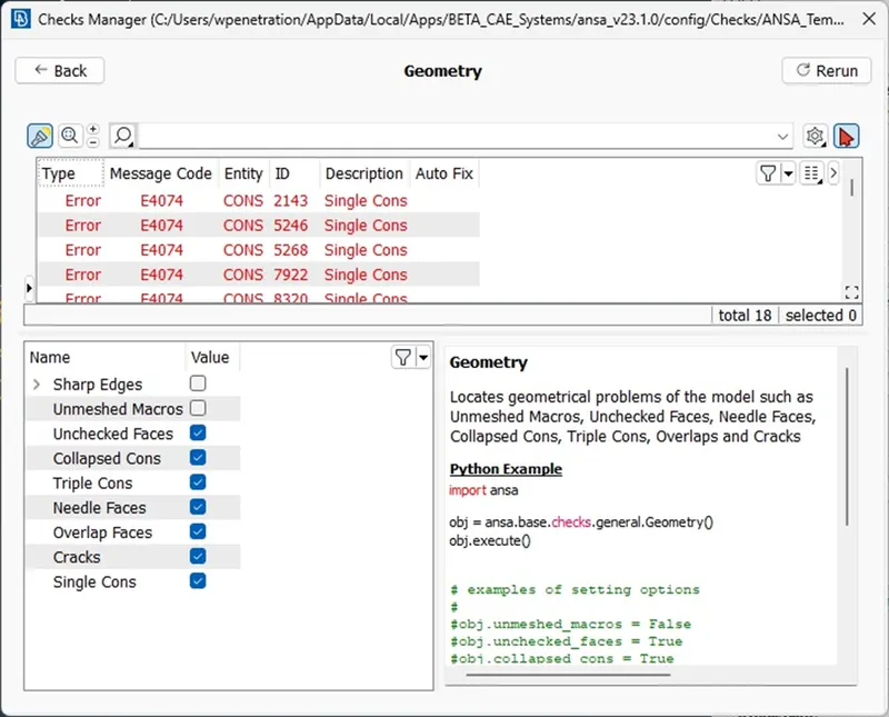
- and Execute the Checks manager and which gives the Errors available in the Model as shown below.
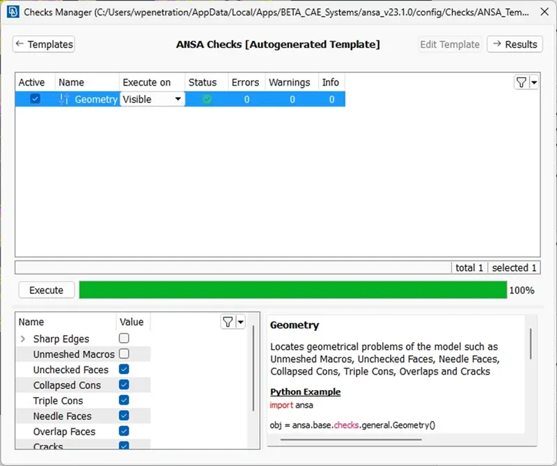
- And Fix the Errors by following the above steps from 5 to 10 after that execute the Checks Manager till it shows no error and 100% meets the geometry requirements as shown below.
- After the Geometry requirements are fulfilled then go for mid-Surfacing by using the below method.
- Create Mid-surface manually by using Faces->Offset->Faces. And ensure the PID Selection Tool is selected in the Feature Selection Manubar after that ensure only ENT Selection Tool has been selected for the entire Process.
- And the visible face is available in the Drawing Area press the middle mouse to complete the action and it opens a pop-up window, providing the offset value -0.75/2 Press OK to complete the action and confirmation dialog box and select No to ensure the Actual Should not be deleted.
- It creates the mid-surface by offsetting one face to the middle of the Model as shown in the below image.
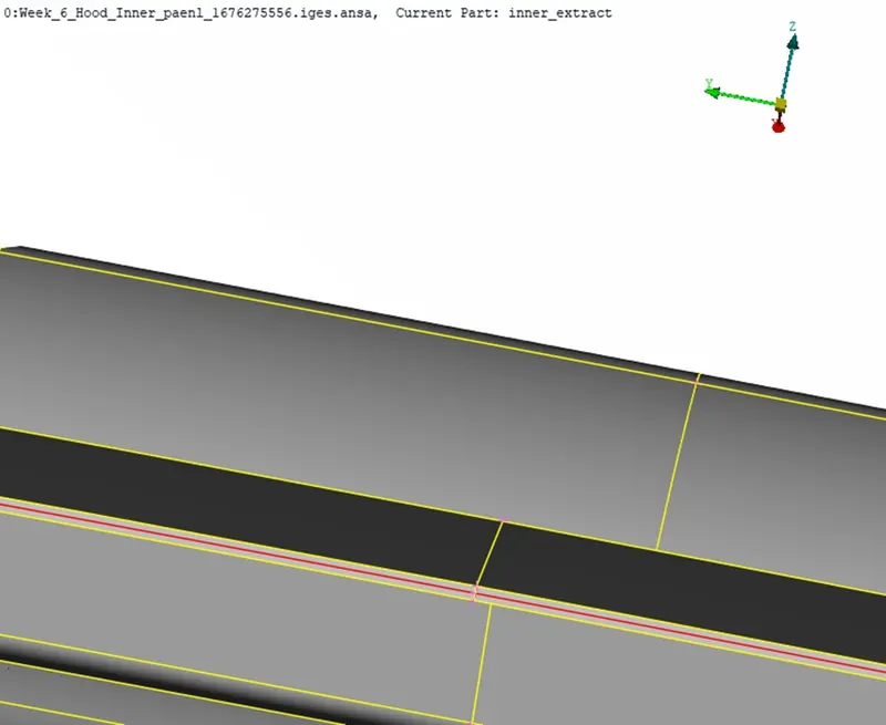
- The Single Cons were in-between the Double Cons are represents the mid-surface of the model.
- Usage Manage Lock View option:-
- Selected whole model using "Or" boolean Comment with selecting the surface of the model and selecting all neighboring surfaces related to the model by area selection.
- Using the LockView option to Store this view as a "model" in Focus Area.
- Open LockView Manager Using Lock->Manage Locks in Drop-Down Manu.
- After that show all entities by pressing "All" Boolean Comment in the Focus Area.
- In Lock_View Manu Select "model" and right-click to go for options in that press Hide the Model only. Now only Mid-surface only Visible. Save this view as "mid-surface" by using right-clicking on the Lock-View menu and pressing New->New Option.
- Provide Thickness to the Mid-Surface:-
- Press Faces->Set PID Option in Modules modules menu. it opens the "Selection Window" in that Select Macros/Shells option Selection whole area using area selection and presses the middle mouse click it opens the "Property Help" Window in that Press right click it shows options. in that select New->Pshell it pop-ups the Property window, fill Values as shown in the below image.
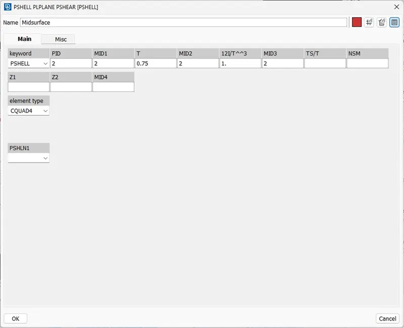
- Then press OK and the surfaces again to complete the action by using the middle click.
- Check the PID is applied to the surface by changing the random color to that PID and using PID mode in Drawing Styles Menu.
- Symmetry Operations:-
- First, hide the Unsymmetry Surface in the Mid-surface area by using "!Not" Boolean Comment. Now Symmetry surfaces are only visible as below Shown image.
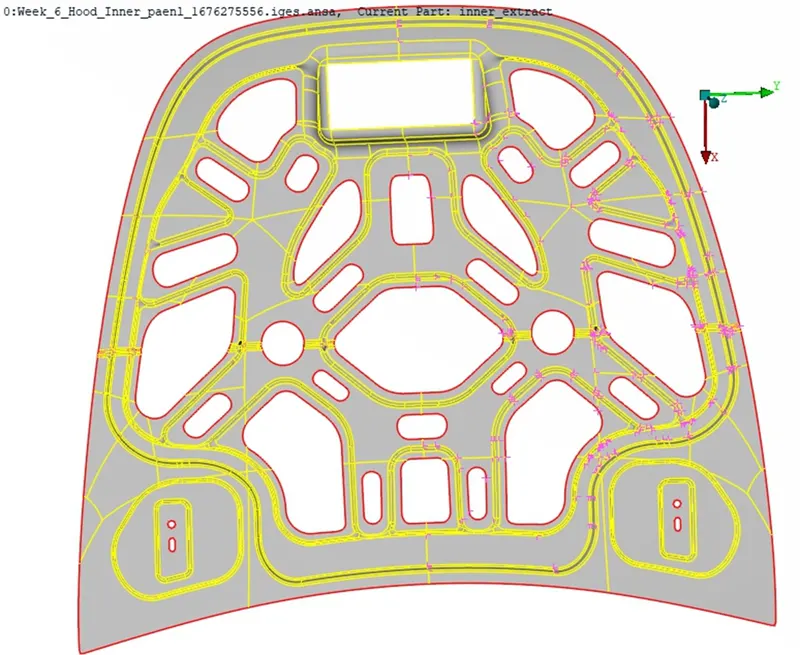
- Ensure the Mid of the surface has the Entities throughout Mid-surface. If not available follow the below steps to Create the Cons throughout the Surface.
-
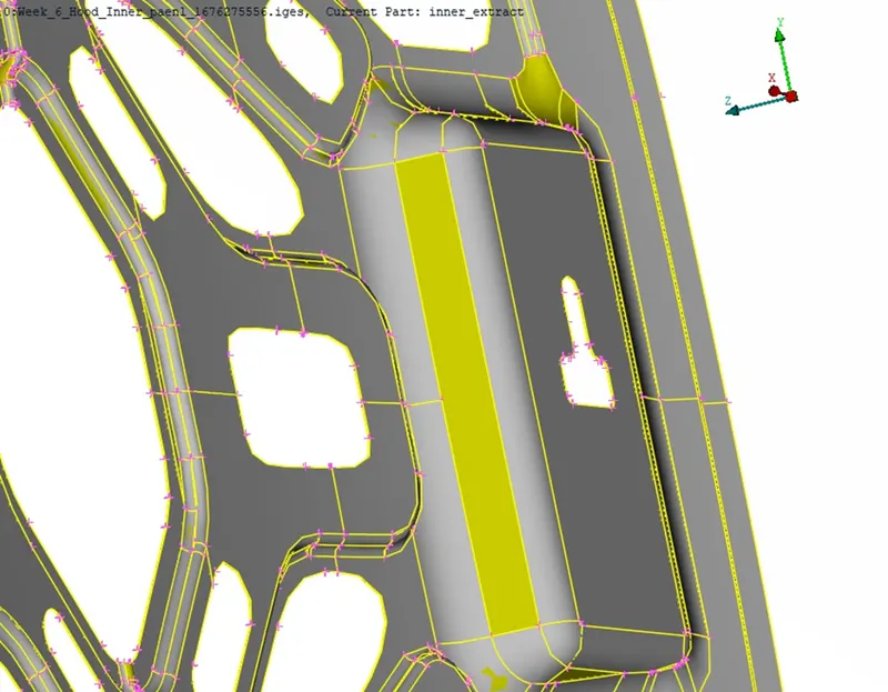
- To Create the mid Line to the Visible area use the Faces->Proj Cut option in the Modules Menu and Select the Hot Points to cut faces into two by creating a new double con in between them. Perform this wherever needed.
-
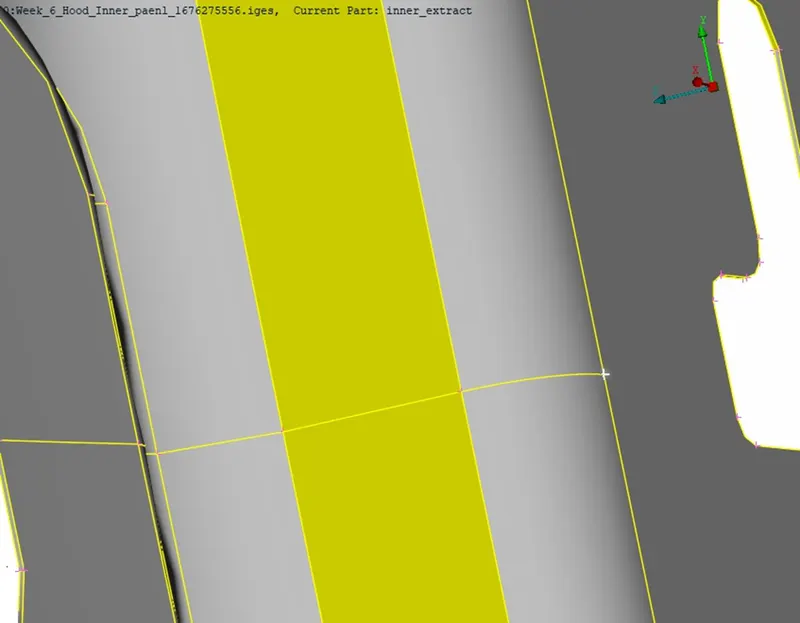
- After that delete the symmetry surface using Faces->Delete Option and the one-half surface by area selection and ensure only necessary surfaces are selected and press the middle mouse click to perform the action.
- Now one-half of the Symmetry surfaces are only visible and save this View as "Symmetry-Surface" in Lock-View Manager.
-
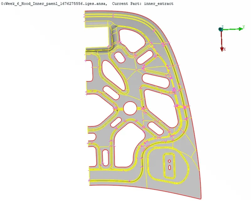
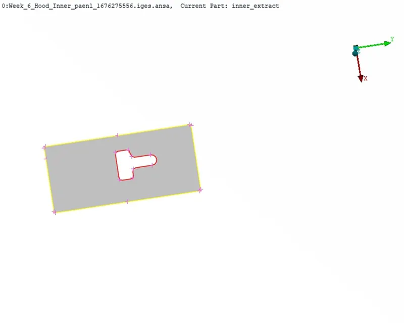
- Now Press the "Invert" Boolean comment to get Unsymmetry Faces visible and save this as an "Unsymmetry-Surface" in Lock-View Manager.
- Performing Mesh Operation:-
- Select only the "Symmetry-Surface" in the Lock-View Manager press show only in Right-Click Selection Menu.
- Ensure the Geometry of this surface by Using Checks->Geometry in the Tools bar. in that Unselect the "Single Cons" option in the Checks Manager, Execute the program, and ensure there is "zero error" & 100% it meets Geometry Requirements
- Now we can prepare the necessary things for the Meshing Operation.
- Perform the Perimeters->Length Option to Ensure the length of each perimeter lengths is 5mm approximately. select the visible area and press the middle click provide the perimeter length value as 5 and press ok.
- Check the Whole area by panning and also ensure the perimeters available in the Holes are Even Numbers by using Perimeters->Number and the Cons in the holes it shows the No of perimeters available in the Hole.
- perform this operation to ensure all Holes have an even No of Perimeters
- Before Going for meshing ensure the below steps.
- Set the Quality Criteria for the meshing by pressing the F11 key on the Keyboard it shows the Quality Criteria window, Provide the following details as given as a task or in objective as shown below.
- Press Apply it applies criteria to the Mid-surface then Press OK.
- If going for Shadow Mode in Drawing Style Menu the criteria are visible.
- To feed the Mesh Parameters to Mid-surface by using Mesh Parameters in the Utilities Menu.
- Provide the values as shown below.
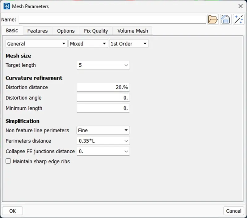
- then Press OK.
- now we can move to the mesh generation by using Mesh Generation->Best->Select. Select the first difficult area and end the action with a middle click.
- Now we can see quality Criteria errors in using the Shadow mode. by Changing the Mesh pattern to remove or avoid these errors by pressing Shell Mesh-> Reconstruct->Select. Select the Meshed Area & press the Middle click to Complete the selection, Ansa process and gives the better Mesh and reduces the Quality Errors.
- To avoid Quality errors by using Elements->Swap, and Elements->Split to reduce the errors.
- Also, use Shell Mesh->Smooth option to smoothen the mesh
- Perform all the above steps to ensure all Half Symmetry surfaces mesh and also there are no quality criteria errors across the surface.
- Copy the Half symmetry faces into full by using Transform->Copy option utility menu. After selecting all areas by using the area selection and press Middle Click. then Ansa Pop-ups Copy Entities Window in that select "Symmetry" in Menubar and Select "Mirror 3 points Plane" in Use Column. select 3 Points across the Mid-Surface. then Press Middle Click and Press OK.
- Now the Meshed Surface is Mirrored we got the Fully Meshed Surfaces.
- Now Select the "Unsymmetry-Surfaces" in Lock_view Manager And press Show Only in Right Selection Menu.
- Provide the Topo to that area to Avoid Single Cons By using the Faces->Topo option in Topo Modules Menu.
- Mesh the "Unsymmetry-Surface" by Following the above-mentioned steps and ensuring the Quality Criteria Errors also.
- Finish Operation and the save the File.
Result:-
As per the requirements we did the Geometry Cleanup, Topology, Mid-Surfacing, and Mesh Generation with all ensuring Quality Criteria as given in the Objective for the Hood Inner Panel as a 3D Model.
Final Result Image:-
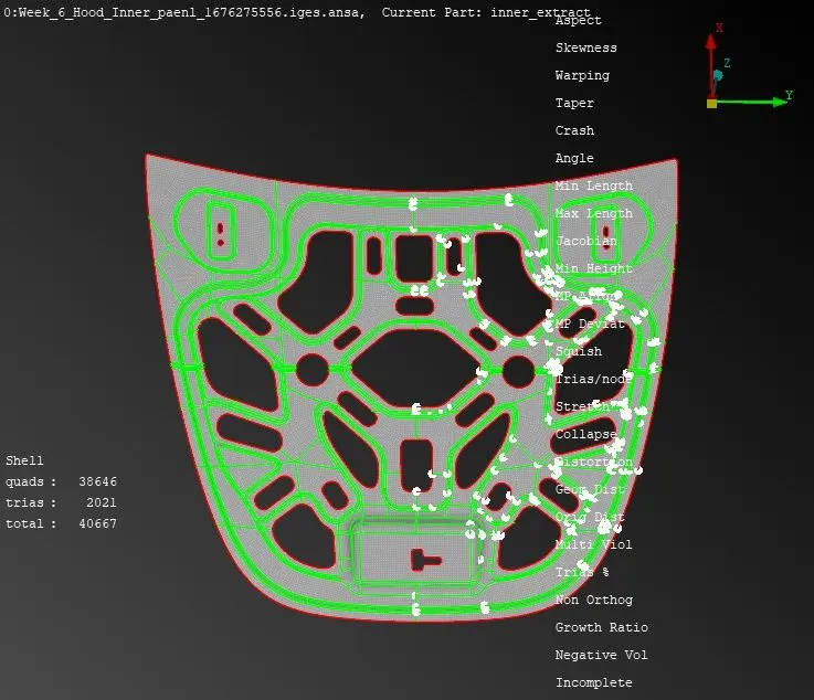
Link: https://drive.google.com/file/d/1JCoPbP8Ua-aLJxAsbV6Kw9uk9BkWoGFl/view?usp=share_link