Week 3 - 2D meshing for Sheet metal
2D Meshing for Car Hood [SheetMetal Component]
Aim -
- To do a Pre-Processing on a given hood model using ANSA Software [Version 19.1.4].
Objective -
- To check the geometrical errors on the hood model.
- To extract a mid surface on the components such as Inner Extract,Outer Extract,Latch Reinforcement Extract and two Hinge Reinforcement Extracts.
- To generate 2D mesh on the components based upon the quality criteria given in the question.
- Assigning thickness to the respective components.
Procedure
Initial Check
- Before working on the model.We have to check the geometry if there are any errors like
- Damaged Geometry.
- Free edges in unnecessary areas.
- Unnecessary points on the lines.
- Unnecessary Connections and connectivity error.
- By assessing the hood model there are no errors in the geometry.
- If there are any unnecessary properties in the property browser,Delete them and then proceed.
- We have to some geometry clean up on the model,Cause there will be some minimal errors in the model.To solve that we should do some geometry clean up on the model.
Phase 3-Geometry Clean Up
- Here we will be doing some geometry checks on the parent component.
- We have to fix the geometrical errors in the parent component,Then only we will be able to extract auto midsurface using skinoffset.
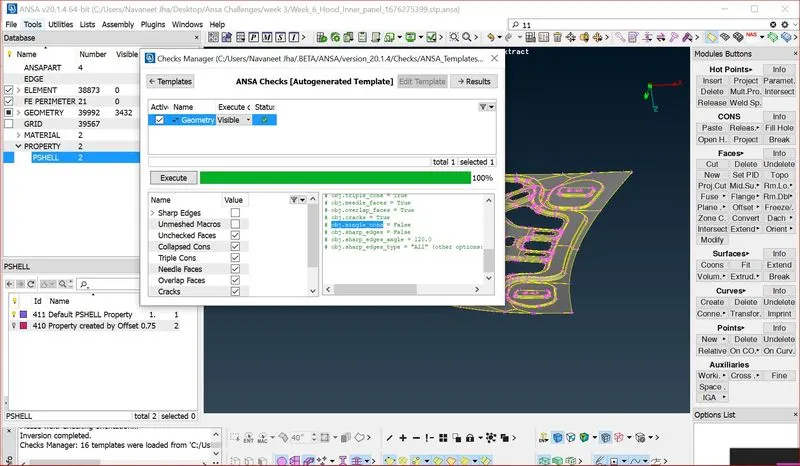
- To fix the geometry checks go to Tool Bar >> Checks >> Geometry.
Step-1
- After clicking on the check geometry,The geometric errors will be displayed.
- We can fix that geometric errors by manually or automatically.
- For this hood model,We can fix that errors automatically by auto fix.
- While checking for errors in the geometry make sure to check this options in the checks manager.
Step-2
Terminologies for Geomerty Options -
- Unchecked faces - Faces that failed for the shadow operation.
- Needle Faces - Degenerated faces are faces that have their opposite CONS coincident.
- Collapsed Cons - A CONS where it's starting and ending position coincide.
- Triple Cons - Areas where three or more faces have a common boundary.
- Cracks - Red CONS at inner areas.[Holes are excluded].
- Single Bounds - Red CONs at outer areas.[Holes included].
Step-3
- Here in the Checks window all problems are reported with red color.
- Under Description column the kind of problem is explained.
- Focus functions are available in order to isolate geometrical problems and handle them easier.Select to fix all or specific reported problems by pressing right mouse button on the header of the list or one or more highlighted problems.
Step-4
- [Note: All problems except triple CONS can be fixed by the automatic fixing.]
- [Note: Right mouse clicking on Check Geometry line, performs an action to all listed problems.In case where not all problems are fixed automatically, retry or proceed to fix them manually.For this component no need to fix manually because all the errors have been fixed with auto fix.]
Phase 4-MidSurface Generation
- Before extracting the mid surface for the components we need to give perimeter and macros length on the components while extracting mid surface.
- This makes the component to get a desired shape,So it will be easy to extarct a midsurface without any errors.The possiblities of errors will be less.
- To give perimieters and macros length on the componets,
- Go to Mesh Module >> Perimeters >> Length.
- Simillarly do the same thing for the macros also.
- Mesh Module >> Perimeters >> Length.
- This tool defines the element length on selected perimeter segments or macro areas.
- The element length may be explicitly declared or may be declared as a factor to be multiplied by the existing element length.
- We can Extract Mid Surface by Two Methods called
- Using Skin MidSurface Option in Faces Panel in Topo Module.
- Using Offset Tool in Faces.
- But for this component,We will be extracting midsurface by using skin.
4:1 Why to Extract Mid Surface ?
- Before extracting the mid surface for every component,We should measure the thickness of the component and then we have to proceed to extract the mid surface.
- If the component thickness is less than 6mm then we will come to know it is a sheet metal component.
- For sheet metal and plastic components,Mid Surface extraction is must.
4:2 Generate Mid Surface
- To generate midsurface
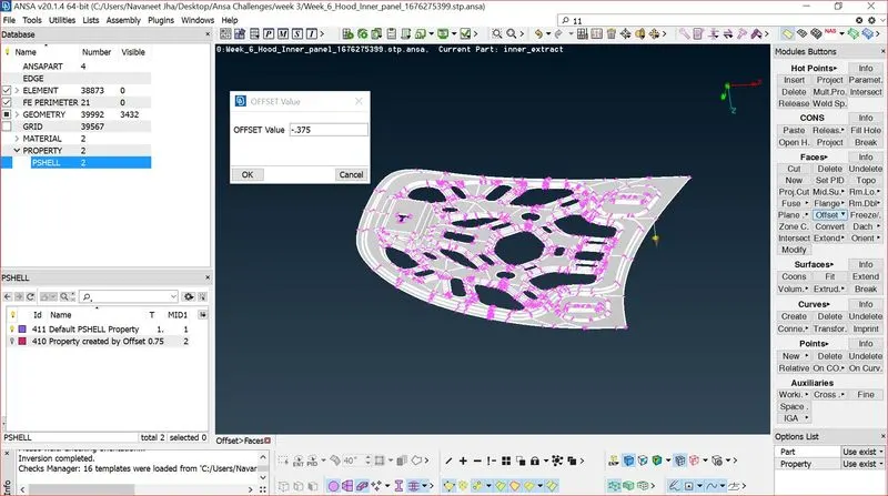
- Go to Topo Module >> Faces >> Mid Surface >> Skin >> Selct the Face >> Give Offset Value and Direction.
- This tool turns the solid description of a thin part into thin shell description by isolating the outer or inner skin of the solid description.
- This Skin MidSurface tool works for only the sheetmetal components which are pressed and stamped.
- It works for the components which have uniform thickness.
- It dosen't works for the components which have varying thickness.
[Note:While extracting the midsurface,make sure to uncheck delete original faces option.]
Mid Surface Extracted.
Phase 5-2D Meshing
- Once geometry cleanup is completed (e.g. surfaces are stitched together — no unwanted free surface edges inside the geometry), meshing is next.
Some rules of thumb when meshing:
- The mesh should look rather smooth and regular (keep in mind that the analysis is based on your mesh and the mesh quality is key.
- Use the simplest element type suited for the problem.
- Start with a coarse mesh and understand the modeling results; then use a finer mesh if needed.
- Try to keep mesh related uncertainties to a minimum if possible. Keep it simple as it can get more complicated on its own.
- Different Element Type Options for Shell Meshing:
5:1 Enter the Parameter quality criteria what they given for the Hood Model
- Select and set the respective quality criteria for the corresponding elements to perform the Quality Checks (Hidden Mode). Also set the general presentation settings concerning the ANSA workspace
- Use the F11 key to open the Quality Criteria and Presentation Parameters management window (F11 Menu).
- Tool Bar >> Quality Criteria (F11) >> Enter the Values.
- Tool Bar >> Parameter >> Enter the Values.
- Now enter the Mesh Parameters
- Go to Tool Bar >> Mesh Parameters >> Enter the Values.
[Note : Save the Mesh Parameter and Criteria file for that component and save it in any other drives,Cause whenever we open that component,we can open the Element Criteria file and Parameter file,So criteria and mesh paremeters will be applied habitually instead of entering again.]
5:2 Conditions to be followed while meshing
- Feature Capturing
- Feature capturing is must while meshing.All the nodes must be connected to the shared edges.
- Tria Management
- Avoig higher number of trias.
- Important Parameter's in tria management
- No trias in corner's or edge's.
- No opposite trias.
- No back to back trias.
- No trias in fillets or hemmings(We can have minimum but anyhow try to avoid).
- No rotational quads.
- No trias should share a boundary with feature line.
- Connectivity between elements.
- Split and perform the mesh.
- Use mixed type mesh for irregular shaped surfaces and quads only for rectangular/square surfaces(Opposite sides should be parallel and equal).
5:3 Begin meshing the surfaces
- Start meshing from the centre regions or from least free edges.You will get proper mesh density and proper mesh flow.
Why Meshing is Needed ?
- Finite Element Method reduces the degrees of freedom from infinite to finite with the help of discretization or meshing (nodes and elements). One of the purposes of meshing is to actually make the problem solvable using Finite Element. By meshing, you break up the domain into pieces, each piece representing an element.
How to Begin Mesh ?
- Start meshing form the least free edges,Like start meshing from the center.
- It will be easy to get proper mesh flow and we will get uniform mesh density.
- Don't mesh form the edges,It will be difficult and you will get many error,So start meshing from the center.
- Choose the element type while meshing.
- For this component we will be using mixed element type and working on it.
- We can also quads element type.This type can be used when we have rectangular surface.
- We can use Tria Element type.This type can be used for 3d tetra meshing.
Start Meshing
- To begin mesh,Switch form topo module to the mesh module.
- Before Meshing set the perimeter and macro length to the component.
- Here set the perimeter and macro length as target element size.
- It will split according to the target element size,So it will be easy for us to mesh.
- To Mesh >> Go to Mesh Module >> Mesh Generation >> Best Mesh >> Select the area.
- While Meshing Switch from shaded mode to the hidden mode,Then only we will be able to see the visibility element quality.
- Here in this region the elements are failing.
- To fix this spit the cons and try to mesh.
- To split the cons go to Macros >> Cut,and toggle the unneccessary cons.
5:4 Assign Thickness to the Components
- Go and assign thickness to the components.
- Go to properties browser and double click on the component which you want to assign the thickness,A new window will pop on the GUI.Give thickness value there.
- Simillarly do the same process for every component.
Phase 6-Final Check
- After Assigning Thickness,Check whether the thickness have been appplied or not.
- To check Go to Utilities >> Quality Criteria >> Presentation Parameters >> Draw Shell as Solid.
- Now check whether there is a proper mesh flow in every region.
- Check whether the elements have captured the feature lines properly.
- And check whether there are trias touching each other.
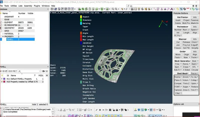
- To check this Go to Utilities >> Quality Criteria >> Edit Criteria Visibilty >> Check Triangles Per Node >> Apply.
- 21 Trias are touching each other,
- Drag them backward.To drag tria backword use paste tool from grids to move them backward.
- To see the trais touching each other.Double click on the OFF.You will be able to see the
Result -
- Hence the mid surface has been extracted to the parent component.
- Hence there are no surface deformations in the geometry.
- A well connectivity has been established between the surfaces.
- The features have been captured properly.
- A good mesh flow have been achieved with the zero elements failing for quality
- Hence tria percentage with 3.9 % have been achieved.
Learning Outcome -
- In this Week 3 Car Hood Challenge,I came to know
- How to extract the mid surface automatically for the sheetmetal components.
- How to clean the geometry .
- How to generate a proper mesh flow with low tria percentage.
- How to assign thickness to the components.