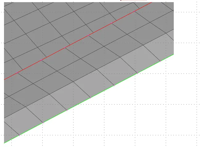
Week 3 - 2D meshing for Sheet metal
- OBJECTIVE
- To mesh the “Hood model” by using geometry cleanup, defeauturing and mid surface by using ANSA processing software . model have to meet the quality criteria to the final generated mesh.
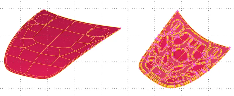
- Hood assembly
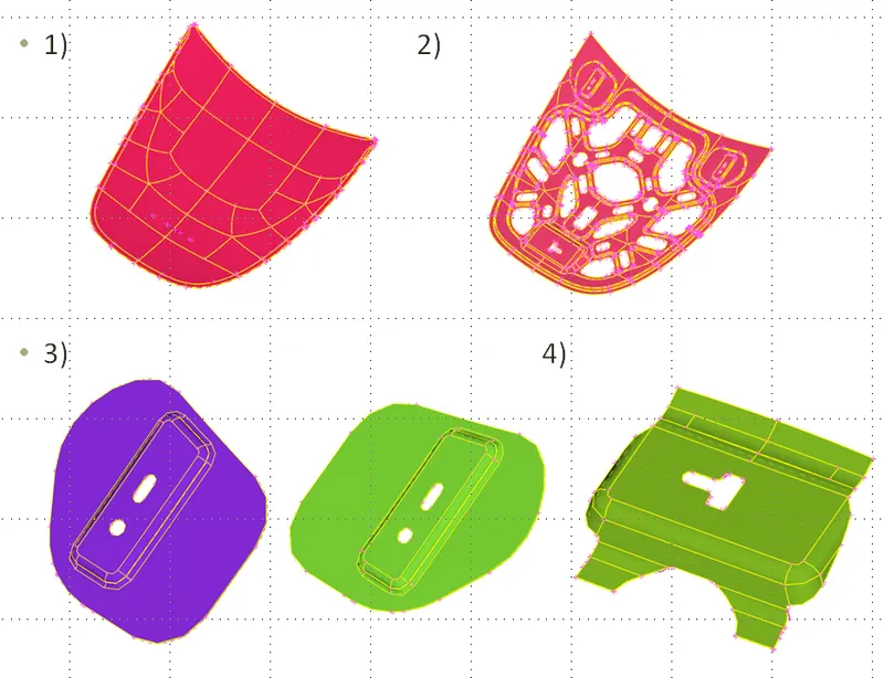
- In this “Hood assembly there are four parts.
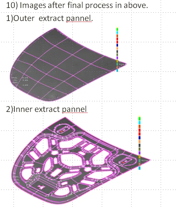
- 1)Outer extract pannel.
- 2)Inner extract pannel.
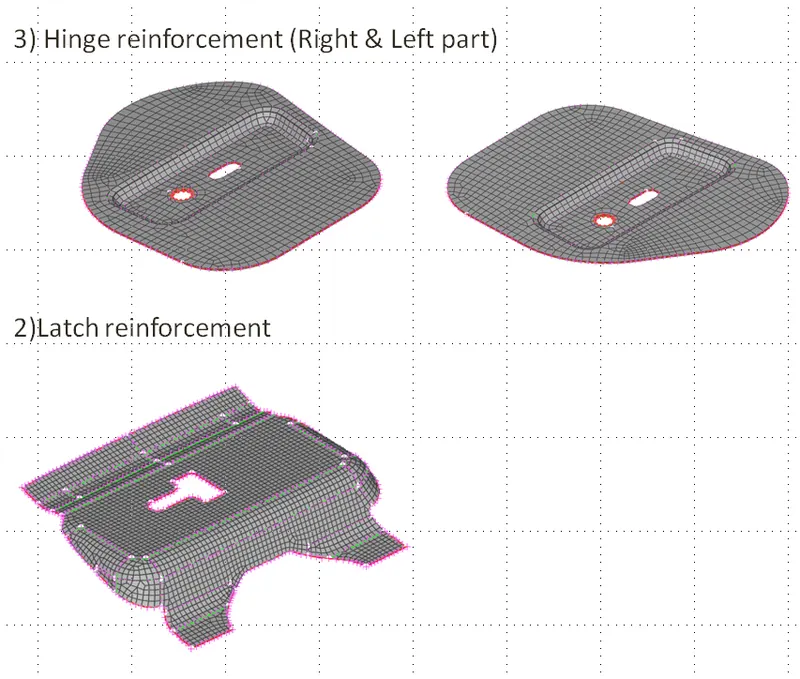
- 3)Hinge reinforcement (Right & Left part).
- 4)Latch reinforcement.
-
- PROCEDURE
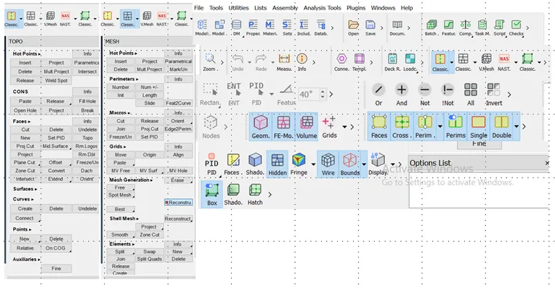
1)Open the file in the ansa software have to set the user working interface & setup the comands which I use frquently as per my requirement as shown in the below images.
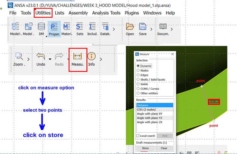
- 2)Each part contain different thickness to measure thickness evertime mesesure point to point by using measure tool (it is present in utilities).
-
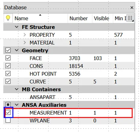
*use store option to save the dimension it is stored in database we can hide & unhide the measurement in database by clicking tick the mark & untick the option as shown in below.
-
*By using this process have to measure the thickness of each and every part of the hood assembly.
-
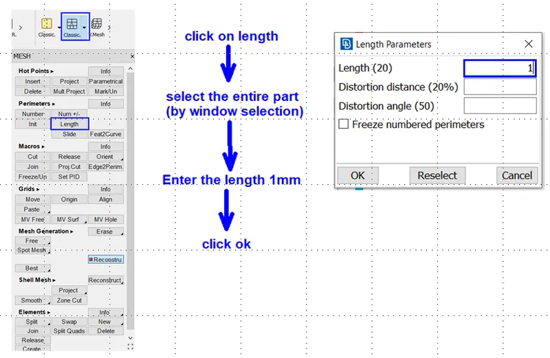
3)Firstly for proper resolution of viewing we have to set the length of the feauture lines by 1mm ,lateron before meshing we are setting the length as per quality criteria..
-
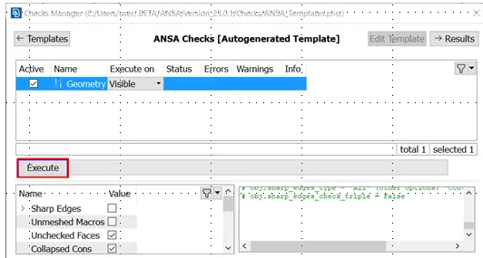
4)Every time before doing any operation have to check the geometry.If fails in check the geomery it effects the final mesh.so,every time should have to check the geometry with out fail for finding geometry errors. This option can find in tools>checks>geometry.

-
Find the interface as shown below. Select the required options for geometry clenup. then click on execute button . After execute we can find the errors present in geometry.these errors have to rectify and proceed for the next step.
- 5)After geometry check next step have to proceed by extracting mid surface.
- *They are two methods to extract the mid surface offset faces and mid surface . For constant thick of parts like sheet metal parts better way to extract mid surface by clicking in a single shot by using mid surface command . for individual thickness means part having different thicknesses like plastic parts have to use the offset command.
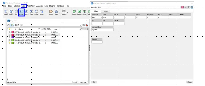
- *Before creating mid surface have to create a individual parameter new pshell for every individual parts .Lists>property>right click>new>pshell>pshell>nameing>ok.
-
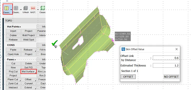
*After click on classic>mid surface>select the entire part> Along the visual direction >giving offset value with estimated thickness and press offset then we get mid surface .
-
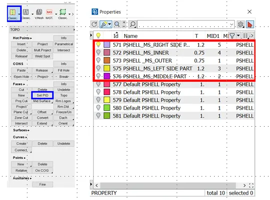
*Generated mid surface have to move to properties which created new pshell property by using “set PID” option. Classic>faces>set PID> selet mid which we created mid surface> middle click>then we get the properties which we created befor We created >double click on property>then mid surface copy in the new property pshell.
-
*In above image shows the properties I created for the mid surface for individual pats.
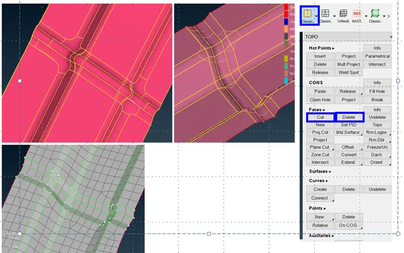
6)After mid surface “Defeaturing surface” is required. In generated mid surface there are number of unwanted curves are generated these curves disturbs the mesh flow. Due to this curves have to defeauture before going to mesh flow by deleting unwanted curves and add the required curves .
-
*For instance in the below image there are at critical edges you can find the unwanted curves are formed.these unwanted curves modified for good mesh flow as shown below.by using cut and delete option we can modify the surface
-
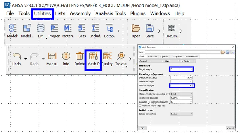
7)After defeauturing before going to mesh quality criteria & parameters have to set .
-
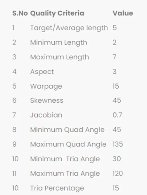
*Utilities>mesh parameters >set the target lenth & minimum length.
- Similarly quality criteria have set. My quality criteria as shown below.
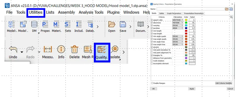
- *After have to set the length 1mm to 5mm as per discussion in above slides.
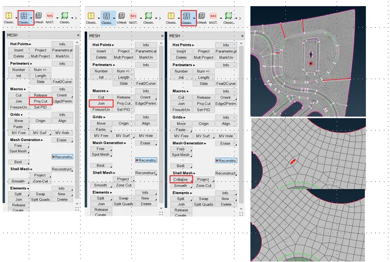
- 8) Then proceed with the mesh flow by using some of the commands are shown in the below.
-
*for getting better mesh. Mesh area will be separated with lines by using cut option (point to point) and project cut (point to perimeter) as shown in above image.these lines can join with join option.
*”collapse” option used to remove the opp triangles as shown in above images.
-
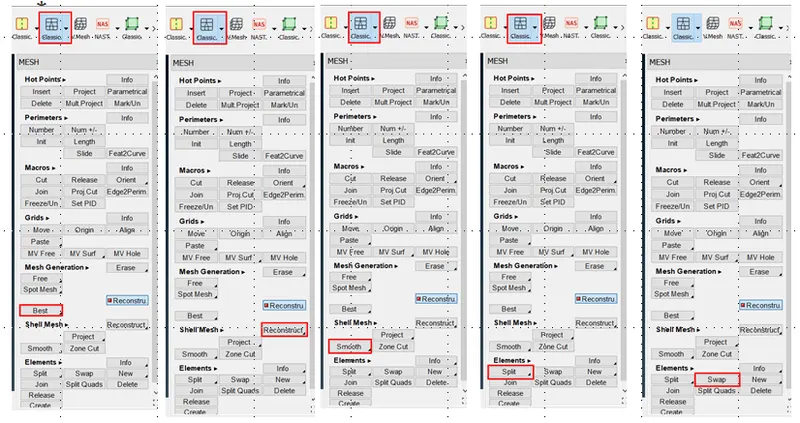
*”Best “ command is used to generate the mesh.
*”Reconstruct” command is used to give better mesh than the generated mesh.
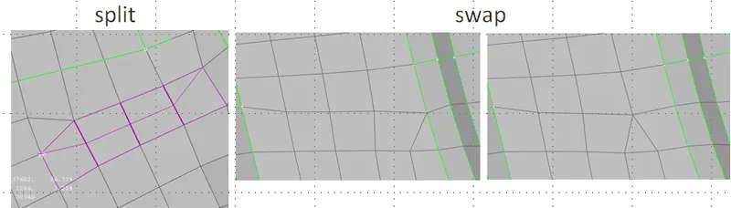
*”split” command is used to add the elements as shown in image
*”swap” command is used to divert the direction of the trias as shown below images .
-
*”Smooth” command is used to smooth the surface every time.
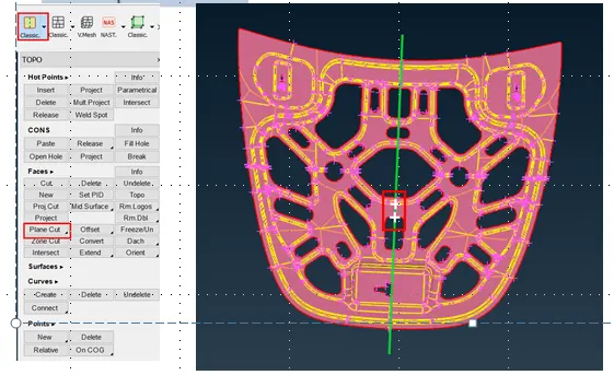
*For symmetric parts have to compare part by two two colours after plane cut
-
Select plane cut option>select two points on the middle to create plane in center> click middle button>the part can be separated into two parts shown in above images.
*Then compare the symmetricity with two colours as shown in the below images.
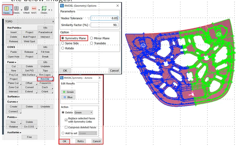
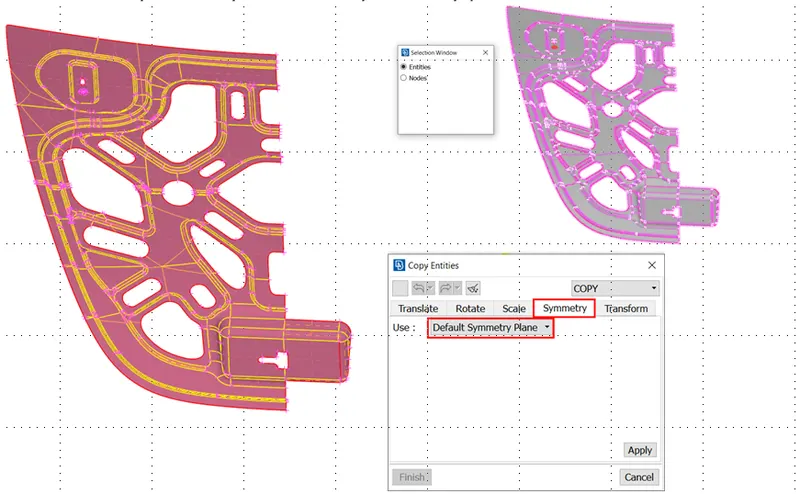
*After comparing if it is symetric then delete the one side of the mesh to save time and proceed with meshing.After meshing one side of the part is transform to another side.utilities> transform>copy>select entities>press middle button>symmetry> default symmetry plane >finish .
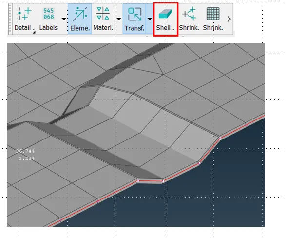
9)Finally thickness must be added to 2d mesh mid surface for further process after pre processing.Presentation parameters> shell>Added to thickness to the 2d mesh surface as shown below.
11) In order to solve this Min length error, One can toggle (suppress) the top and bottom double cons at the fillet region of a mid surface in outer extract pannel.