Week 3 - 2D meshing for sheet metal
https://drive.google.com/drive/folders/1C9uQN4QKZ1yZJzlF9jVqGLdzmmmqu2RT?usp=share_link
OBJECTIVE- To mesh the hood component after proper geometry cleanup and midsurface creation using the ANSA preprocessing software. Also, to ensure the generated mesh follows the given quality criteria and the corresponding thickness of each surface is assigned to the mesh
Step-1. The part has 4 main components and different thicknesses. They are as follows: Inner Panel, Outer Panel, Hinge Reinforcement and Latch having thickness of 0.75mm,0.75mm,1.2mm,1.2mm respectively
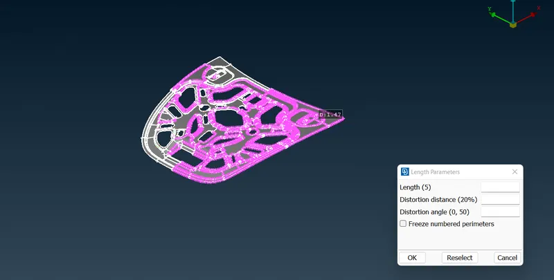
Step-2-Initially, the part will not have proper resolution so to ensure proper detailing and viewing, we can use the length option which can be accessed through the Mesh module. This tool creates a finer representation of the model based on how finely the length of the feature lines is broken into. All the surfaces need to be selected to use this tool
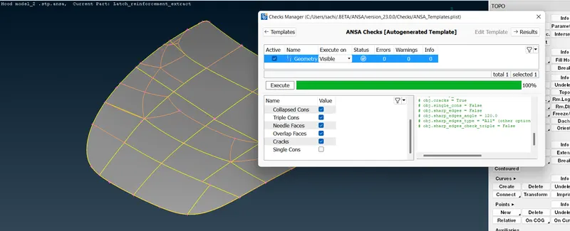
3. Then we need to perform a geometry check-up. For geometry check up go to the checks manager then execute to check the geometry then need to fix the geometry of the part
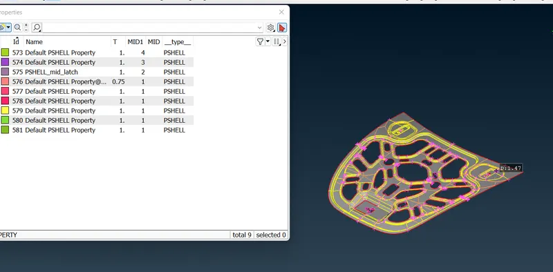
Step-4-After cleaning up (and reorienting the faces of the part - using the 'orient' tool), we can assign properties and property IDs to accommodate the midsurfaces that will be created. Doing this will also make it easier for viewing components separately. To create a property, go to properties from the upper toolbar and right-click the list. Then go to New > PSHELL > PSHELL to create a new property ID.
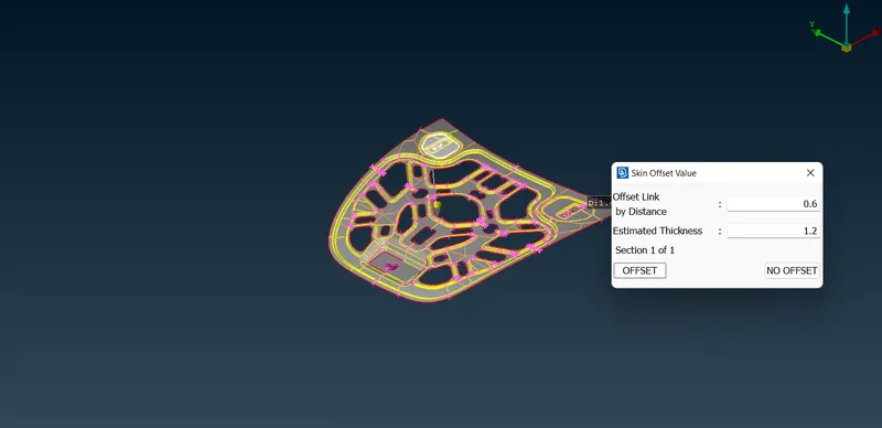
Step-5. Then generate the midsurface of each surface. This can be done using the 'midsurface' tool in the faces menu or using the 'offset' tool from the Topo module.After selecting the offset tool, it will ask to select the surfaces to offset. We can select the surfaces on one side of the component. After that, we can assign the offset value (half the thickness).
STEP-6. After midsurface is generated for each of the components, we can go ahead and prepare to mesh the midsurfaces. To start we can assign the quality parameters as per the challenge. We need to access the 'mesh parameters' and 'quality criteria' options from the top toolbar. And then we can assign the values as per the table. The mesh type will be 'mixed' and minimum and maximum lengths would be 2mm and 7mm respectively and add quality criteria all specifiactions as per the requirements and SAVE it
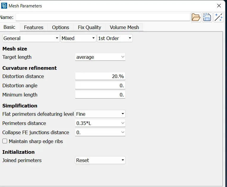
STEP-7. After that we can go ahead and assign the target length. This is done by accessing the 'length' tool again from the Perimeters section under the Mesh module. We need to select the entire midsurface and assign the target length (FOR HOOD it is 5mm).
STEP-8 Before we go for meshing we need to clean up the geometry like
- Avoiding & removing unnecessary hot points
- unnecessary line on flat surface
- NO sharpedge surface
by doing join & cut options
Step-9 After preparing the surfaces, we can go ahead and mesh them. We need to use the 'best' mesh option, which can be accessed from the 'Mesh Generation' section. for meshing we need to mesh like an one way flow for each part
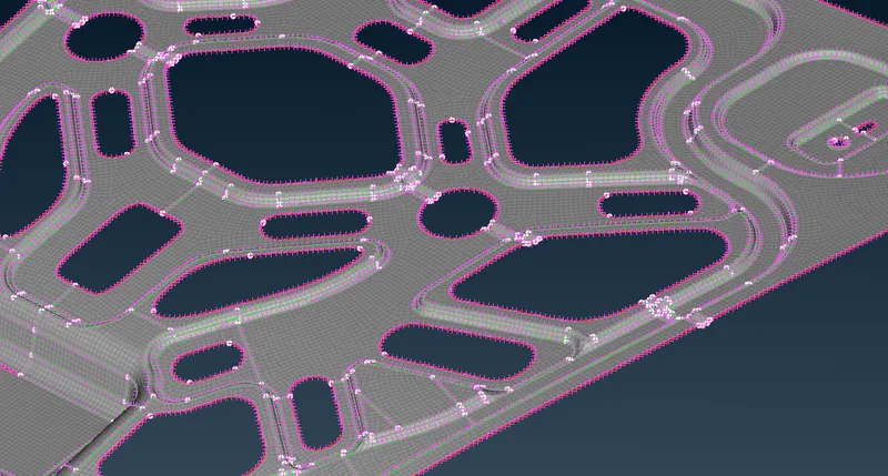
STEP-10. After meshing a section check & analyze the mesh and see if it can be improved. If it can be improved, we can make use of the 'Reconstruct' or "smooth" tool from the Shell Mesh section in the mesh module. It basically meshes the selected mesh keeping the quality criteria in mind and tends to produce a better mesh flow
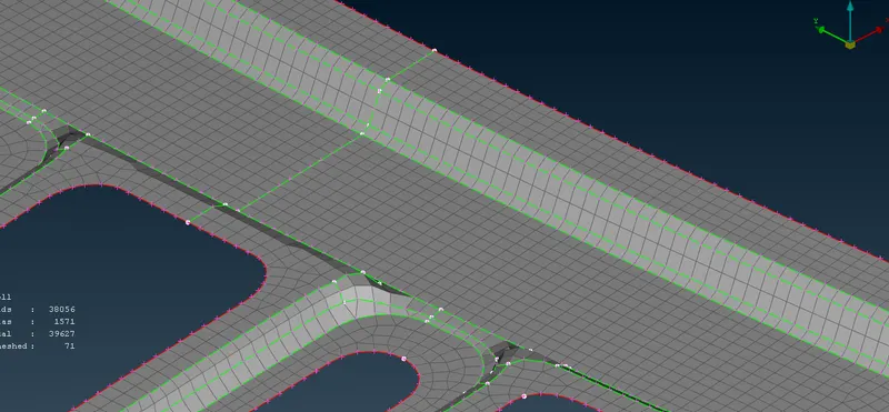
STEP-11 After meshing please apply quality criteria on meshed parts and check whether the meshing is passing all the quality criteria