Week 3 - 2D meshing for sheet metal
AIM: To generate a 2D mesh on the sheet metal part. This meshing to be done by taking the mi surface of the parent geometry given. By performing above task learn different commands in the Pre-processor ANSA.
PROCEEDURE:
STEP -1 : Initially the length of the macros & perimeter of the parent geometry is adjusted to 1mm. This gives the fineness to the CAD features.
STEP -2: Check the geometry for the criteria like triple cons, single cons etc. If there is a presence of any problems in the geometry parameters it has to be corrected
STEP -3: The model in this project is a sheet metal. So in the case of sheet metals, we can go for meshing by taking the mi surface of the parent geometry.
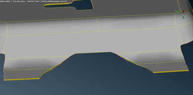 This is the image of the parent sheet metal geometry for which mid surface has to be created
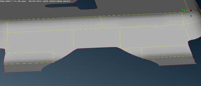 This is the mid surface of the above shown parent geometry.
STEP -4: Clean up the geometry by supressing the unwanted cons & replacing the feature cons with the cons with the new ones for getting a proper mesh flow.
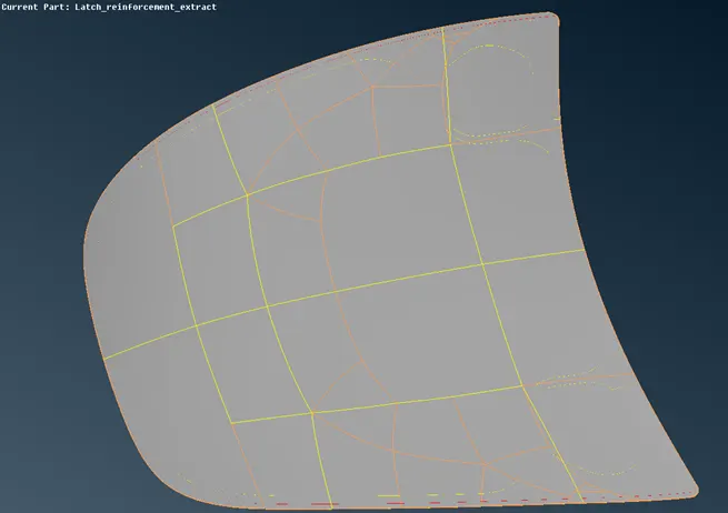
Orange cons: These are the original cons of the feature of the model. These are the cons which are actually present in the Model
Yellow cons : These are the divisions created
STEP -5 : Check for the symmetricity of the geometric model.
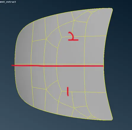
Here the region-1 & region-2 are symmetrical to each other about the split axes shown. So, the meshing is provided to either one of the regions and the can be transformed.
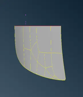
So, the half of the model once meshed then we can use the transform option & just mirror the entire meshed surface on the other end for the second half.
STEP- 6 : After analysing for the symmetricity of the structures now the entire model is divided into smaller rectangular regions to get a proper mesh flow.
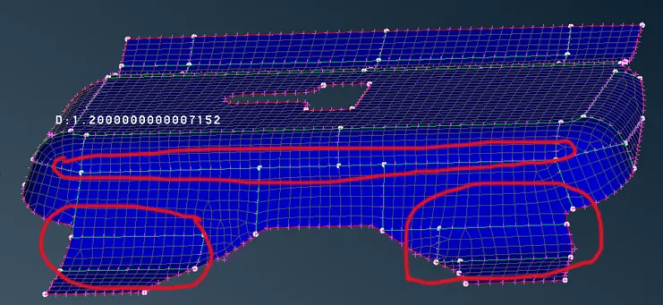
Here the regions highlighted with red inks represents cons which is externally created in order to get a appropriate flow pattern
STEP – 7 : Once the regions are cut into smaller rectangles the mesh quality criteria is given. These quality criteria in this case are
- Skewness = 45
- Wrapping = 15
- Jacobians = 0.7
- Min length = 2
- Max length = 7
Etc.
STEP – 8 : Now by selecting each of the macro rectangular region the best mesh option is used for generating mesh.
STEP- 9: ‘Reconstruction” command helps to automatically improve the mesh flow in a particular macro region.
LEARNING OUTCOMES & CONCLUSIONS :
In 2D meshing there are two types of meshes are formed namely QUADS & TRIA.
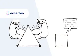
- TRIAS are highly stiff compared to QUADS, so we try to minimize the number of the TRIAS in the mesh flow.
- TRIAS could be toggled & moved using SWAP,SPLIT,PASTE,COLLAPSE options.
- No rotating QUADS or rotating TRIAS are preferred in the mesh flow.
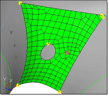
- No TRIAS are allowed in the periphery region of the model.
- No TRIAS are allowed on the sides of the holes in the model.
As in both the above cases the stiffness increases which will affect the mesh results.
- The quality parameters has to be set and verified after meshing.
- If model is symmetric about any axis or plane, we can mesh one of the sides and mirror it on the opposite sides.
- However, in the converging regions the TRIA formations are inevitable.
- Maintaining the equal number of nodes for the divided region might help in reducing the number of TRIAS formation.
CONCLUSIONS :
This project helps to conclude the following points:
- The mesh flow is very important for simulating the results for the entire model. This mesh generation has to be strategized using some ground rules.
- The stiffness of the entire mesh model should be as low as possible.
- Some regions of the model should be taken care separately for the mesh generation eg. Fillet regions & Hemp regions.
- In the case of sheet metals mid surfacing could be used for lower computation time