Week 3 - 2D meshing for sheet metal
AIM: - MESH THE GIVEN HOOD GEOMETRY ACCORDING TO THE GIVEN QUALITY CRITERIA.
Objectives:
Take the Mid-surface of each component of the hood geometry.
Mesh the mid surfaces according to the given quality criteria.
The given challenge was completed using the ANSA tool and the steps taken in doing so are as follows.
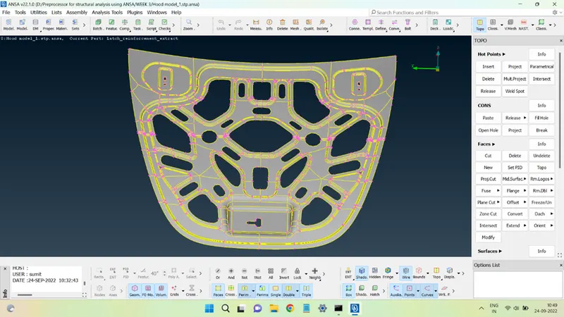
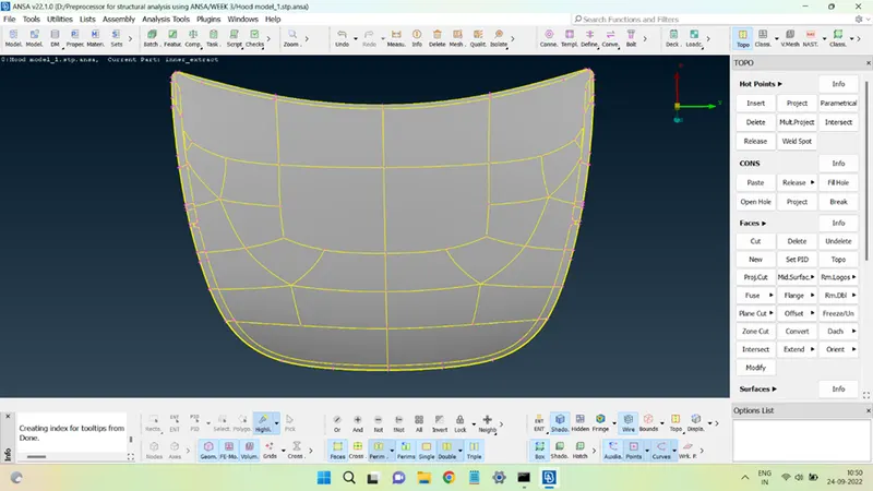
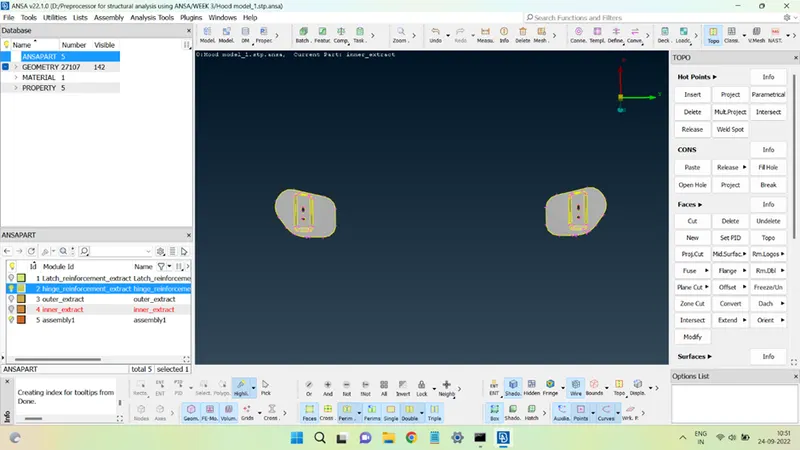
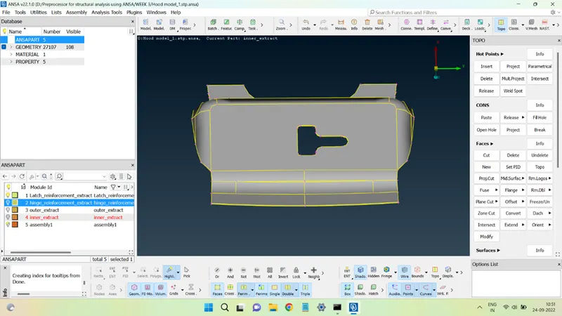
STEP 1: Import the given Hood geometry into the ANSA environment. The parts of the geometry will look like this:
INNER EXTRACT:
OUTER EXTRACT:
HINGE REINFORCEMENT EXTRACT:
LATCH REENFORCEMENT EXTRACT:
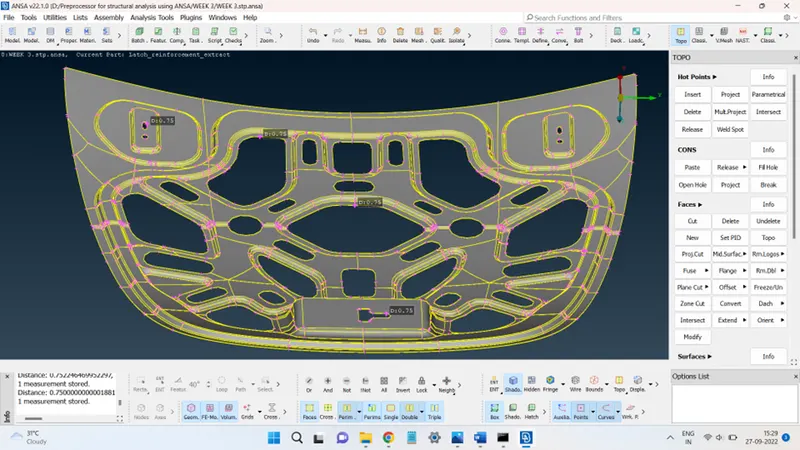
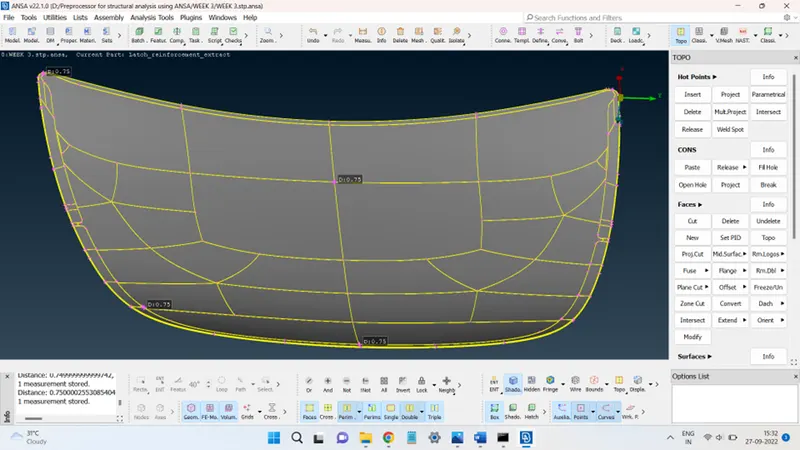
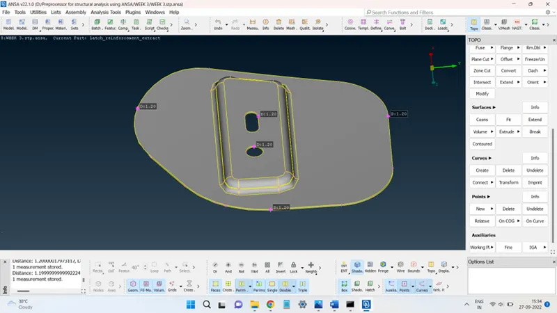
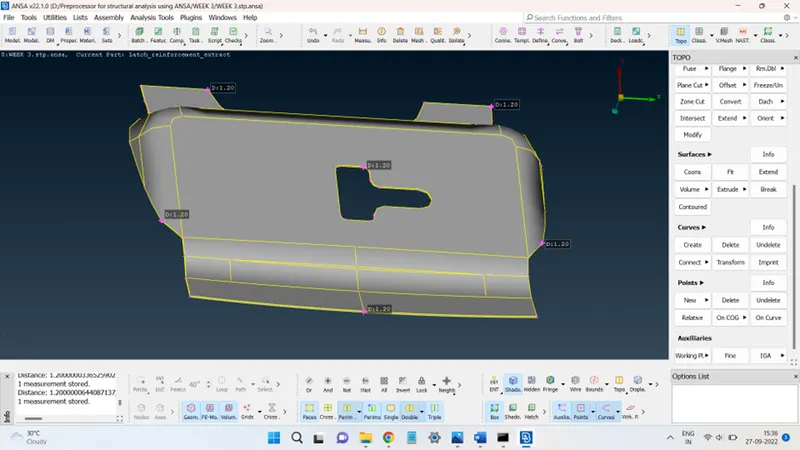
STEP 2: Check the thickness of each component.
The thickness of each component is shown in the below figures.
INNER EXTRACT:
OUTER EXTRACT:
HINGE REINFORCEMENT EXTRACT:
LATCH REENFORCEMENT EXTRACT:
STEP 3: Geometry check.
Checking all the part geometries whether any errors are present in them, if present those errors must be removed.
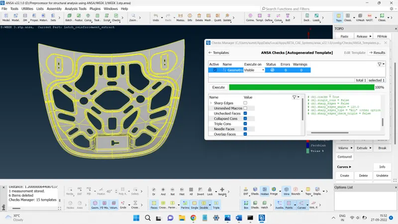
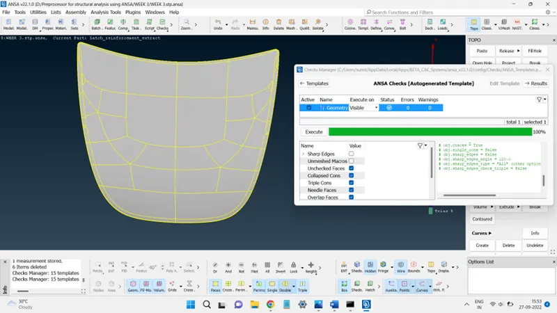
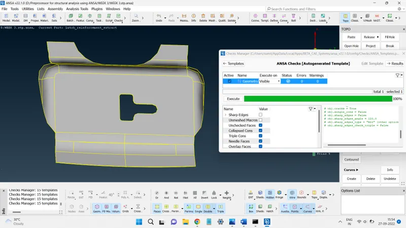
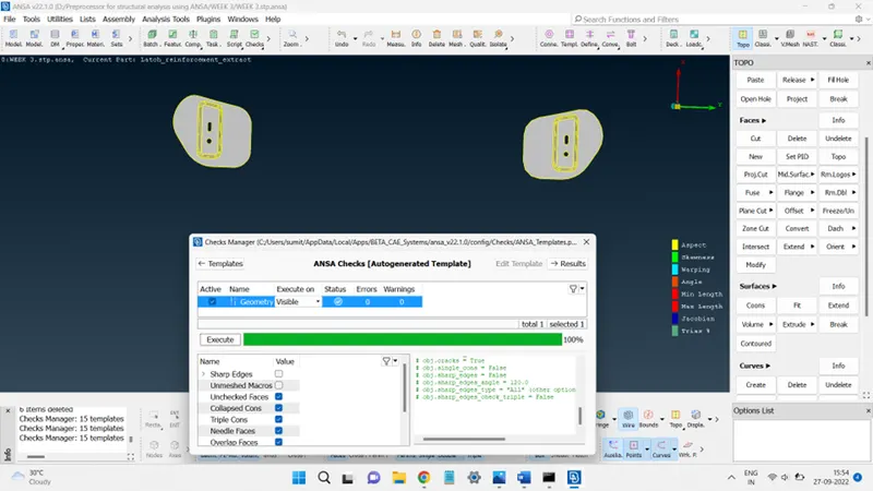
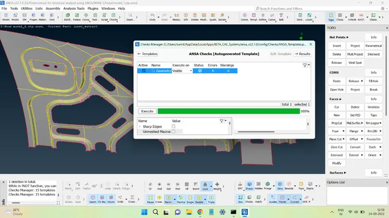
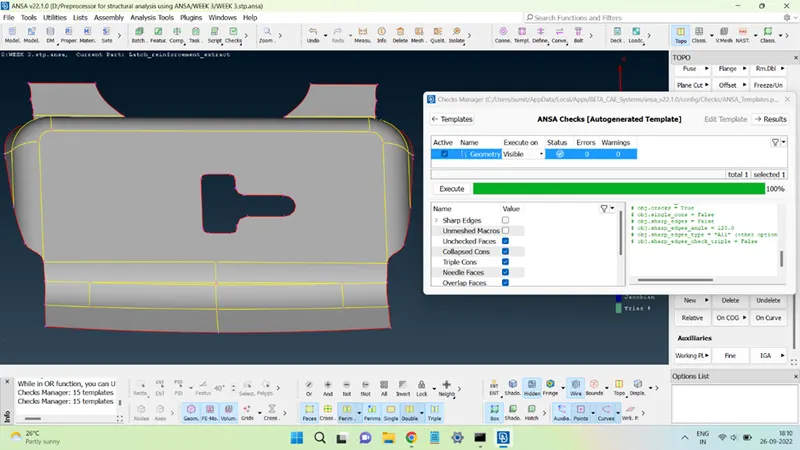
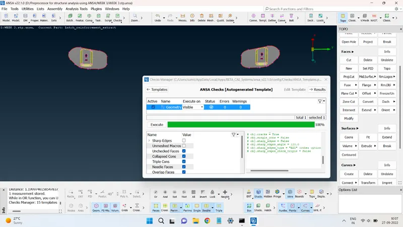
The geometry check was done by clicking on the Checks panel and selecting Geometry from the drop-down menu. Next, a window will open showing all the different geometry check operations that will be done in the background by ANSA. Click Execute to begin the check and if errors are present, they will be reflected in the window, if not, the window will show a 100% message. The geometry check for each part is shown below:
INNER EXTRACT:
OUTER EXTRACT:
LATCH REINFORCEMENT EXTRACT:
HINGE REINFORCEMENT EXTRACT:
STEP 3: Mid-Surface generation.
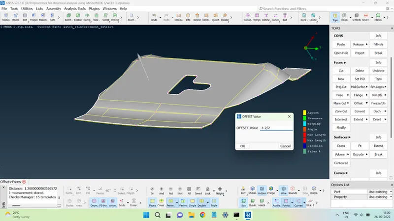
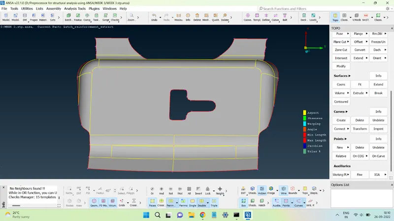
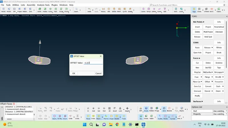
The mid surface for each part was obtained using the Offset tool present in the Faces panel of the Topo deck. The top surface was offset by a distance equal to half of the thickness for each part. All the surfaces (to be offset) were selected through the Feature Angle selection tool and offset by an appropriate distance. The obtained mid-surfaces are shown in the figures shown below.
INNER EXTRACT:


Since this part is symmetrical, therefore only one half was selected for offset. A geometry check was also performed on the above surface before moving on to meshing. The same process was followed for the remaining parts.
OUTER EXTRACT:
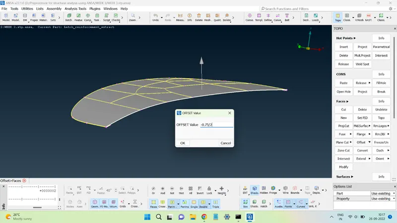
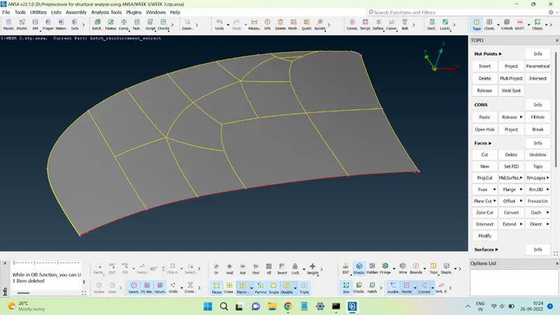
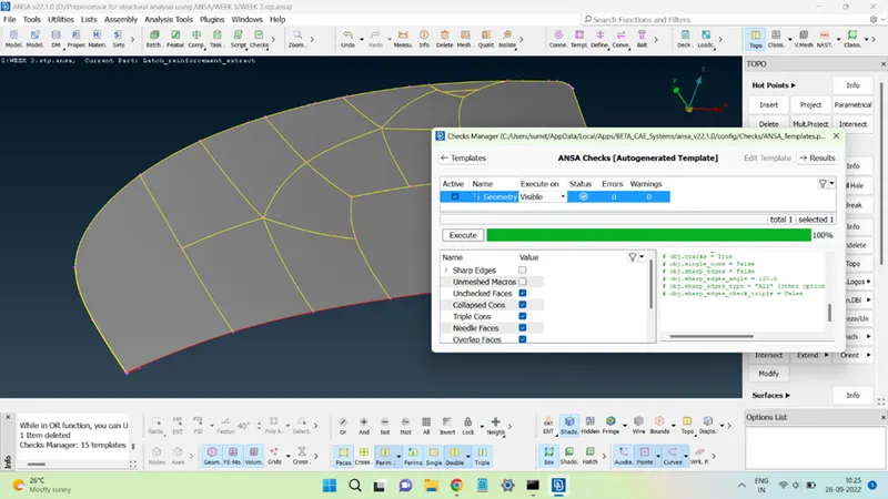
LATCH REINFORCEMENT EXTRACT:
HINGE REINFORCEMENT EXTRACT:
STEP 4: Meshing.
Each of the mid surfaces obtained was meshed according to the following quality criteria settings.
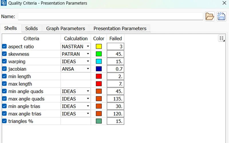
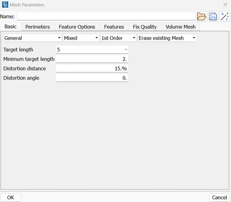
Also, the perimeter length was changed to 5 mm with the help of the Length command present in the Perimeter panel of the Classic Mesh deck.
The mesh obtained for each component mid-surface is shown as follows:
INNER EXTRACT:
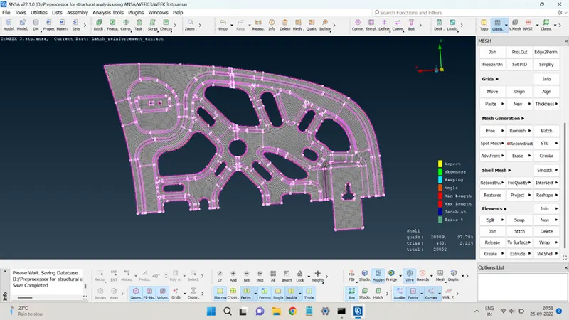
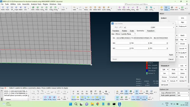
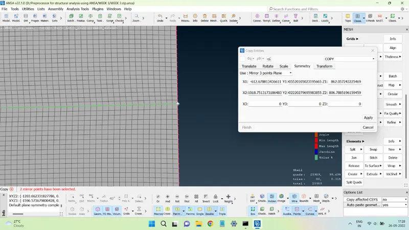
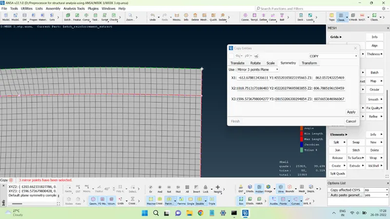
This mesh was then reflected about the symmetry plane to get the complete mesh geometry. It was done using the Transform command and selecting the Copy option from the drop-down list. Select the entities to be copied and middle click to confirm, a window will open, select the Symmetry option and then select Mirror 3 Point Plane against the Use option.
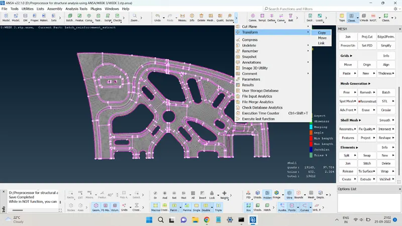
The points selected are shown in the figures below.
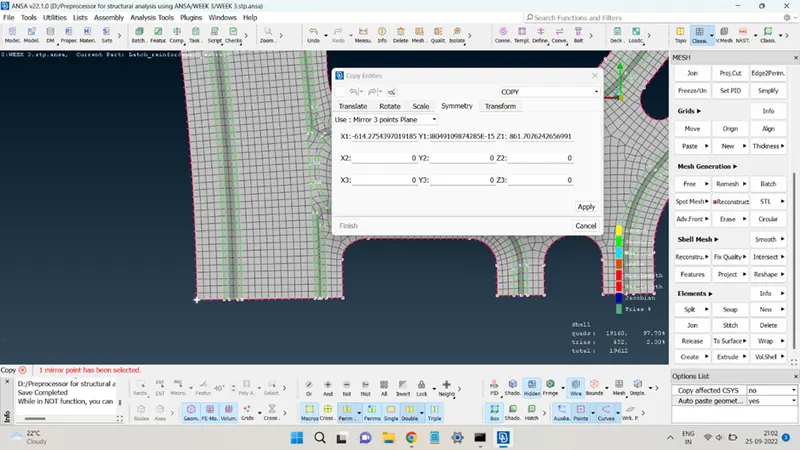
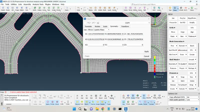
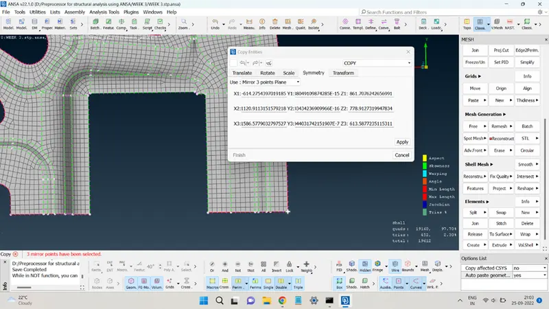
Click on Apply and then on OK to finish.
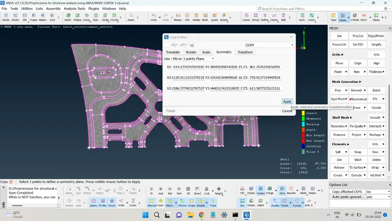
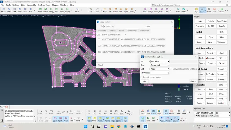
The mesh after reflecting the geometry will look like this:
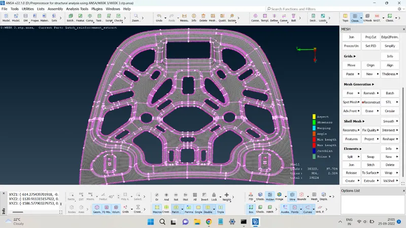
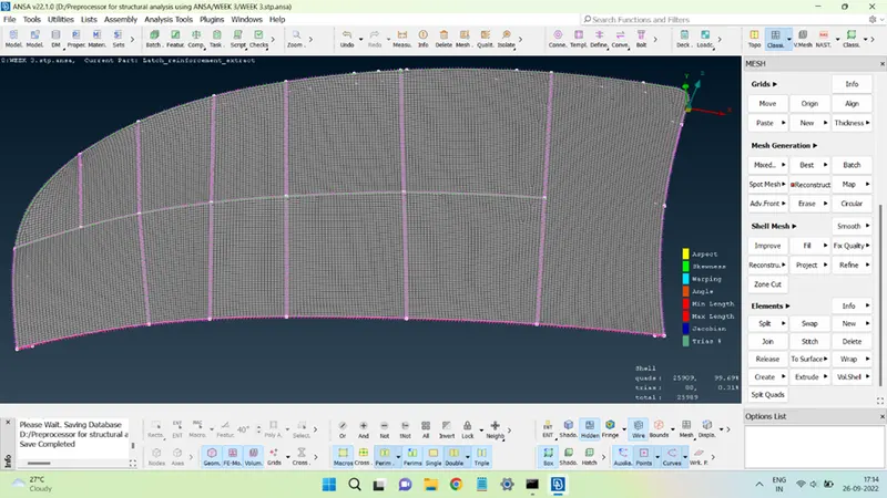
Now, adding the unsymmetrical face to the above mesh will complete the meshing process for this part and mesh will look like this:
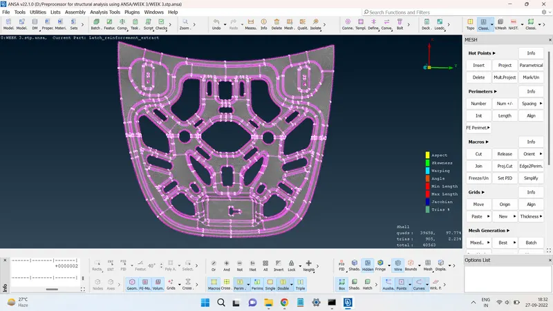
Here, the symmetry operation was carried out upon the mid surface and the elements associated with the mid surface were also reflected along with it.
This same process was also done for Outer extract.
OUTER EXTRACT:
Reflecting the geometry
The mesh will look like this:
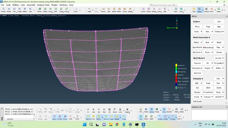
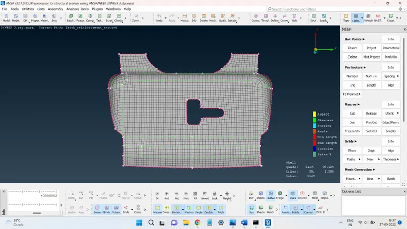
LATCH REINFORCEMENT EXTRACT:
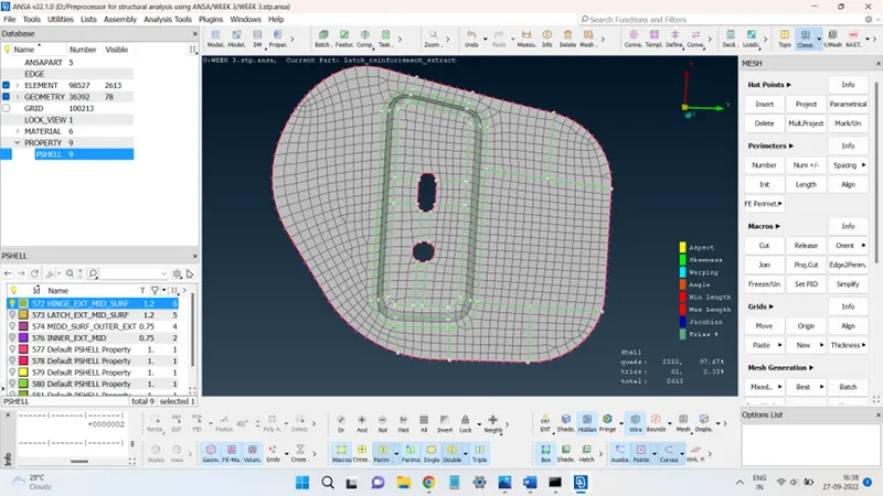
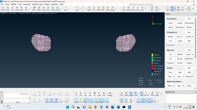
HINGE REINFORCEMENT EXTRACT:
STEP 5: Quality checks.
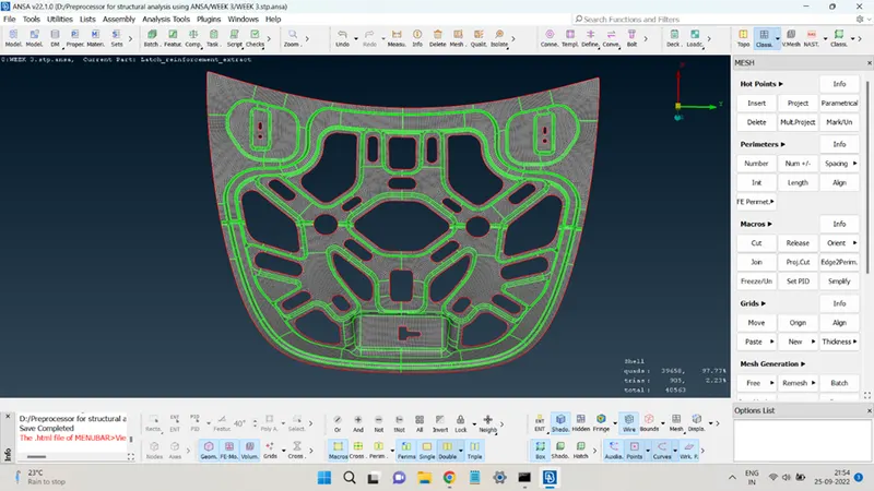
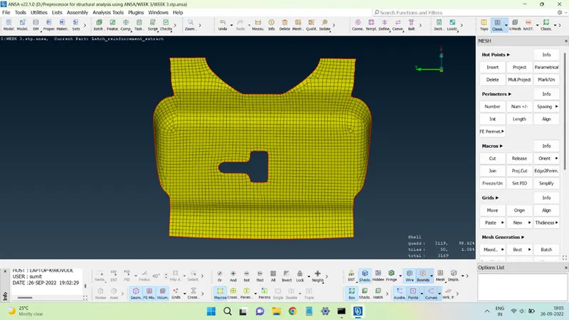
The generated meshes must pass the quality criteria setting and apart from that also pass certain other checks like No free edges and proper Normals Alignment.
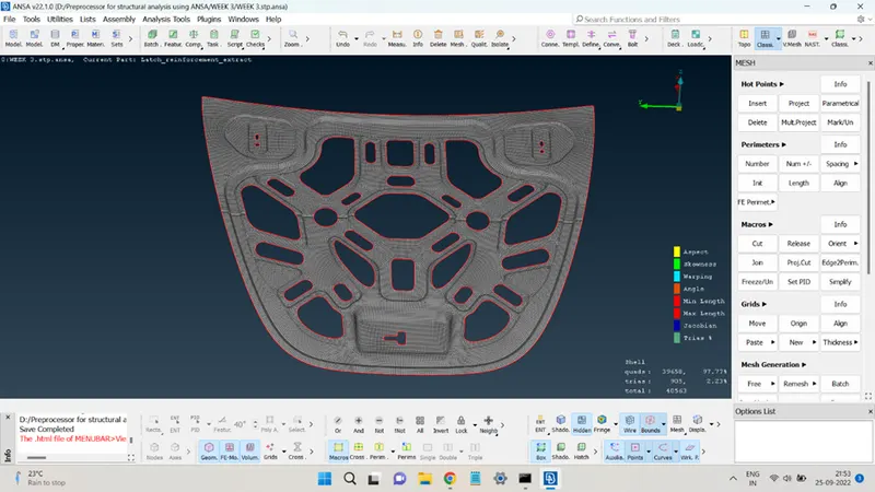
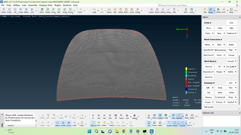
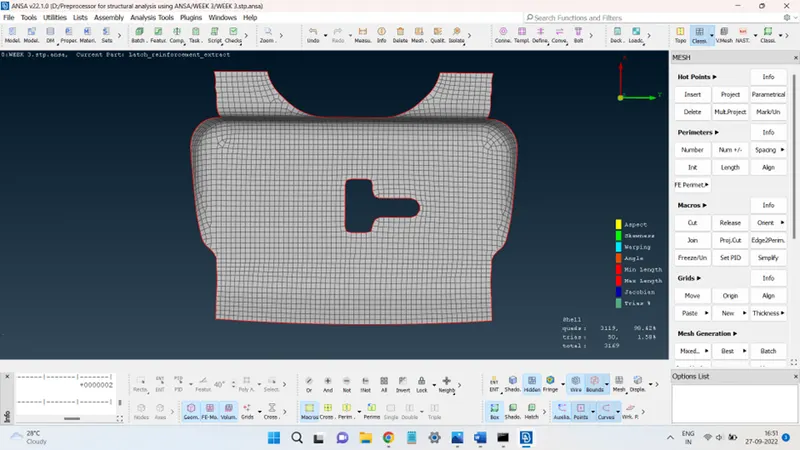
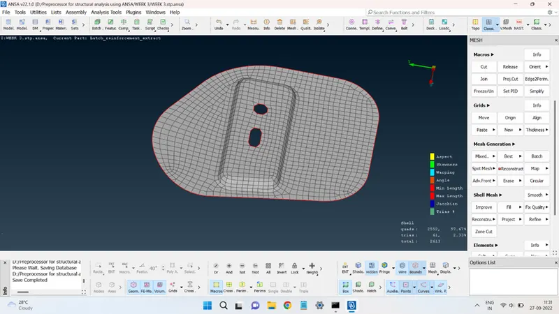
The quality criteria check for each part is shown below:
INNER EXTRACT:
OUTER EXTRACT:
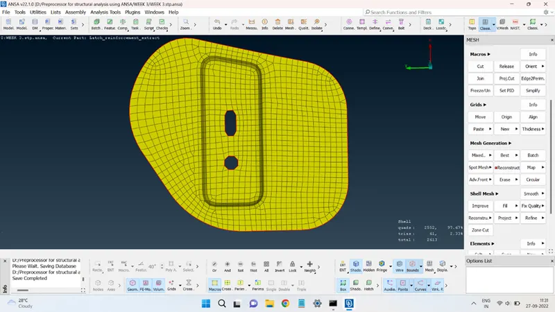
LATCH REINFORCEMENT EXTRACT:
HINGE REINFORCEMENT EXTRACT:
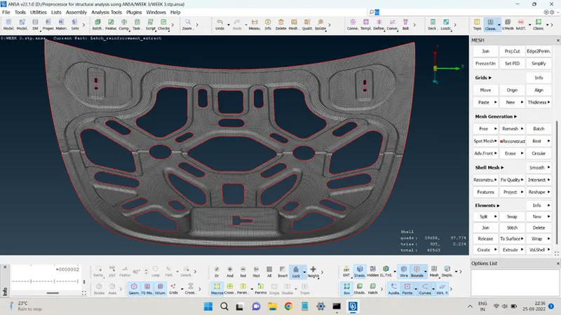
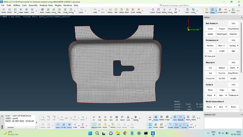
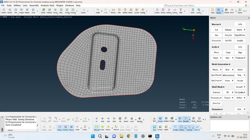
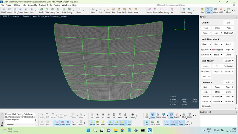
FREE EDGES:
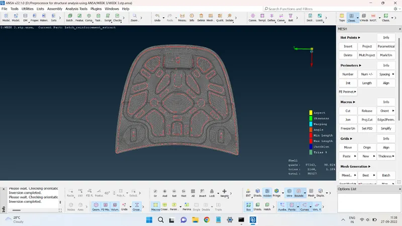
The free edges (or cracks in mesh) are checked by turning Off all the perimeter highlight options and turning on the Bounds. The bounds command will show the gap, if present in the mesh, if not, it will show only the geometry boundary.
The free edges check results for all meshes are shown in the figures below.
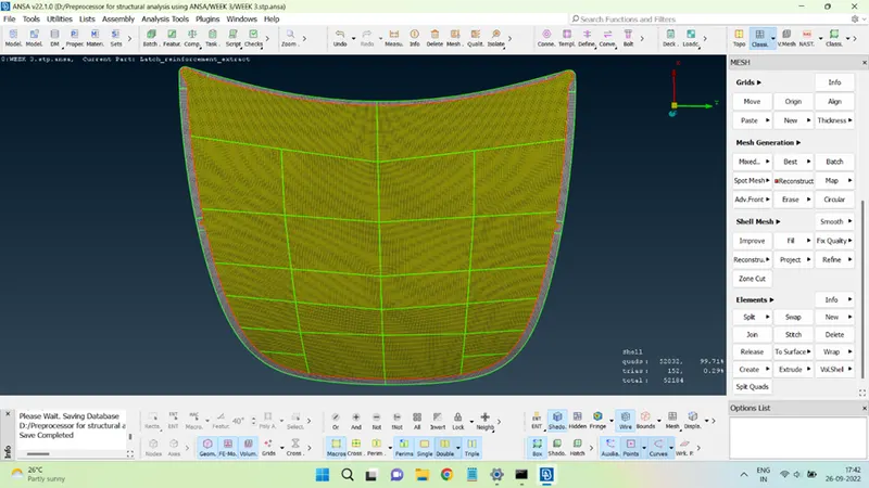
NORMALS:
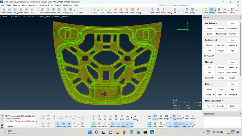
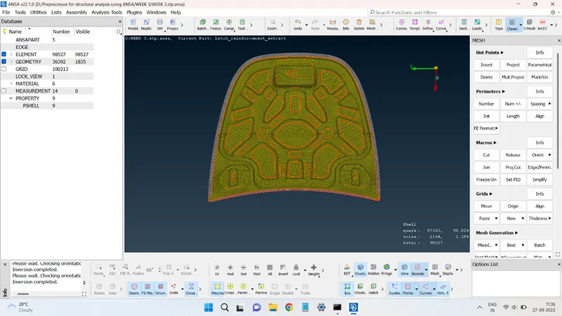
The normals of all the elements must remain in the same direction otherwise, the mesh will behave inappropriately under the loading condition.
In ANSA, the normals are designated by specific colors. The gray color represents one direction and the yellow color represents the opposite normal direction.
So, all the elements either must have a gray color or yellow color when viewed in the Entity mode. The normal for each mesh is shown in the figures below.
STEP 6: Creating PIDs and applying thickness.
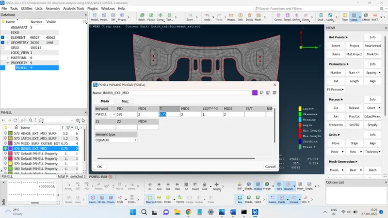
Now, each mesh geometry is saved separately by creating the Property ID for each of them and the thickness is also added to the mesh through these PIDs.
A new PID is created by selecting the Set PID command present in the Faces panel of the Topo deck. To create a new PID, right-click and select New and create the PID.
The PIDs for each mesh geometry is shown in the figures below.
INNER EXTRACT PID: INNER_EXT_MID and thickness = 0.75 mm.
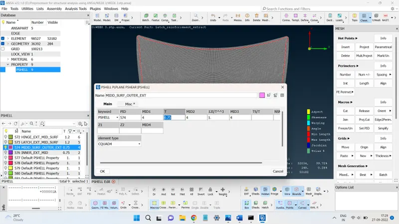
OUTER EXTRACT PID: MIDD _SURF_OUTER_EXT and Thickness = 0.75 mm
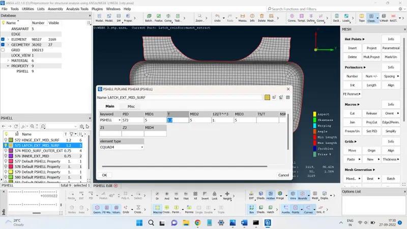
LATCH REINFORCEMENT EXTRACT PID: LATCH_EXT_MID_SURF and thickness = 1.2 mm
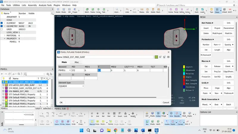
HINGE REINFORCEMENT EXTRACT PID: HINGE_EXT_MID_SURF and thickness = 1.2 mm
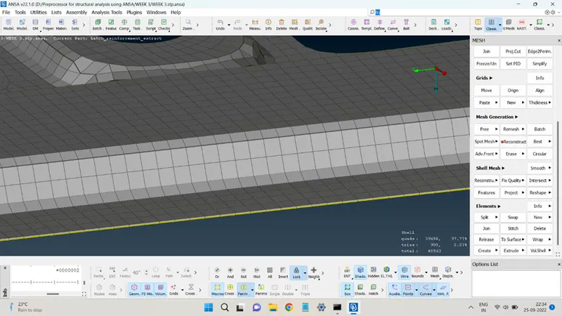
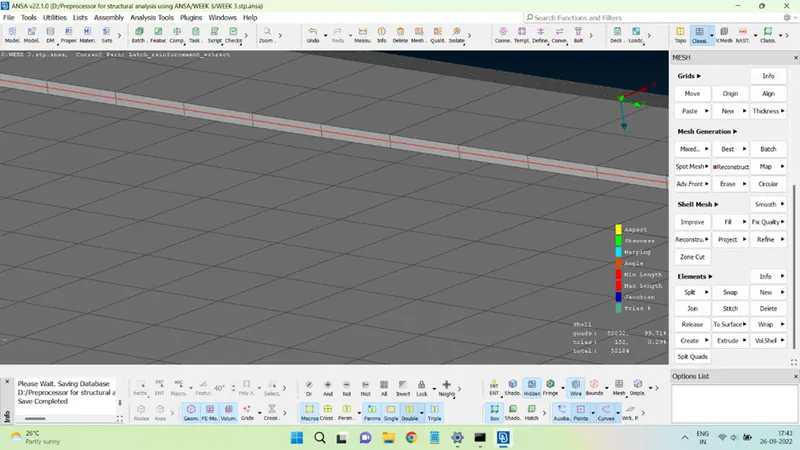
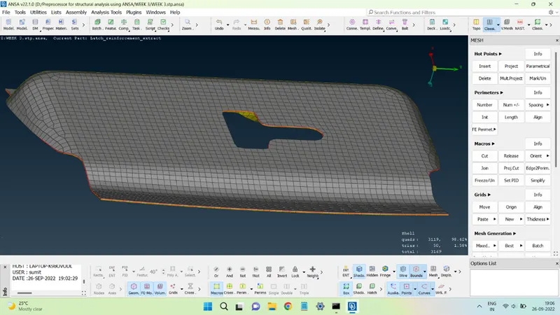
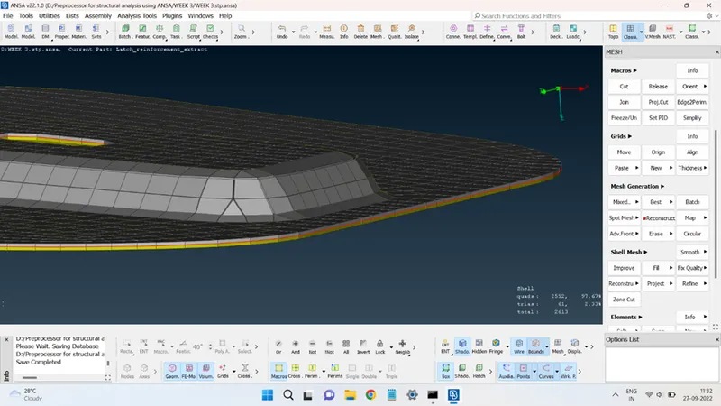
The mesh viewed with element thickness turned on is shown below:
The combined mesh of all the parts of the hood geometry is shown below:
Conclusion:
This challenge allows learning how to work using ANSA to generate the: Mid-Surfaces; Mesh & PIDs of complicated geometries.
It also makes the user familiar with other useful commands which are essential for having a proper mid surface and a good mesh.