Week 3 - 2D meshing for sheet metal
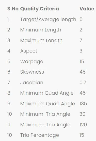
Objective: To create mid-surface of the given model of a car hood, and create a smooth mesh with the given elemental quality criteria:
Meshing Process:
Importing the model: Firstly, we imported the model from the storage in .STEP format to ANSA software.
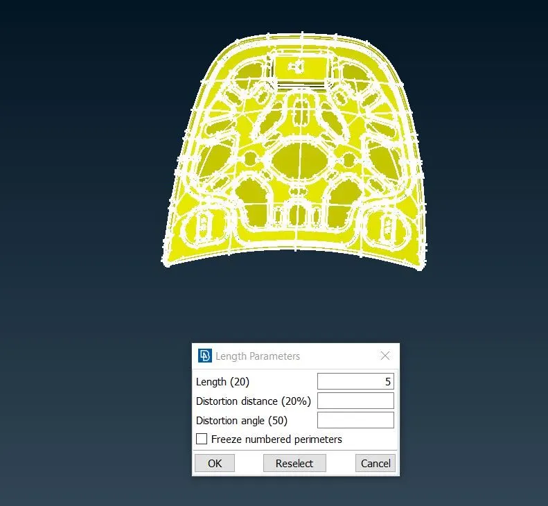
Cons resulution: For this I have selected length option in perimeter group.
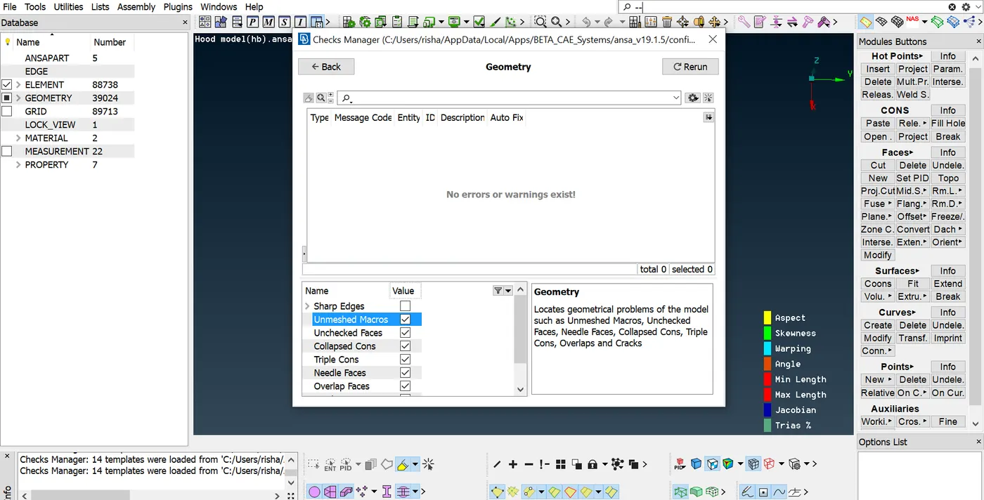
Geometry Check: From ‘Checks Manager’ using ‘Geometry’ we checked for any geometrical errors. And fixed using Auto Fix options, however for some manual fixing was required. For example, for releasing a triple con from a whole and converting it into in Double Con.
Similar processes done for both the inner and outer part of the hood.
Extracting Mid-surface; Now for getting the mid-surface of the hood cover, we used Faces>Mid-surface>Skin option to extract the mid-surface. And a separate PID had been assigned for the mid-surface if hood cover. As the cover surface was smooth and had no elements on it we used skin option.
Also, considering complete inner hood as a single element, including latch and hinges a mid-surface was created using Offset>Feature Angle. And we assigned a PID for the inner hood, giving a distinct colour code for the same.
After completing, with extracting mid-surface we assigned the thickness for both the elements, i.e. 0.75 for both inner hood and hood cover.
Dividing into equal half
For dividing the hood I have gone through midpartion line to check if there is any line missing after that I selected delete option and selected half part of hood then middle click on it to create half part see pic
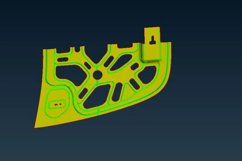
After that I used cut with right click to remove extra lines and delete option to remove extra hot points
After that I created various cuts to create quadrilateral type shape
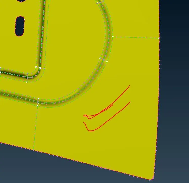
After that I used BEST option to created a mesh wiithin region
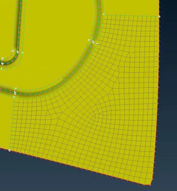
After that I used split option to remove tria elements for following conditions
After that I used smooth command to make it smooth (see above pic its after reconstruction-> split-> smooth) & then do remaining part meshing
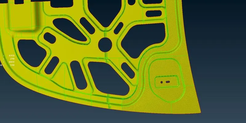
AFTER MANY TIMES DOING CUTS USEING BEST OPTION -> RECONSTRUCT-> SPLIT(If applies)-> SMOOTH WE ARE SUCESSFULL IN DOING FULL MESHING
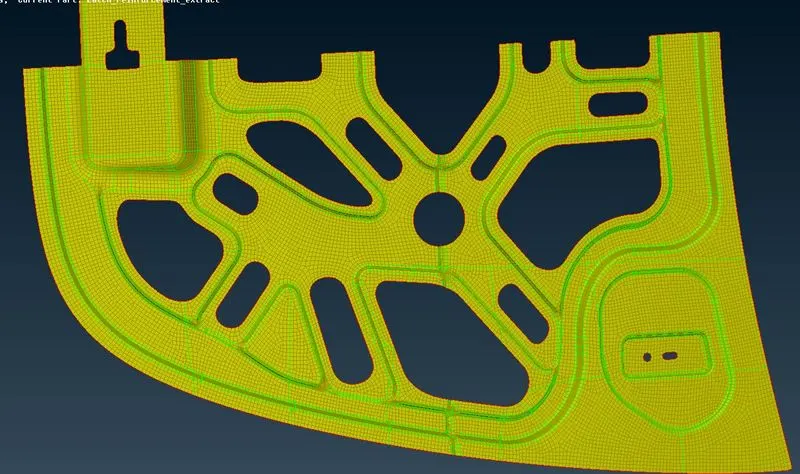
\\Plz note that I have changed color of mid surface yellow to grey because I have some EYE issue so bright lisht is not good for me kindly ignore it\\
After midsurface is generated for each of the components, we can go ahead and prepare to mesh the midsurfaces. To start off, we can assign the quality parameters as per the challenge. We need to access the 'mesh parameters' and 'quality criteria' options from the top toolbar. And then we can assign the values as per the table. The mesh type will be 'mixed' and minimum and maximum lengths would be 2mm and 7mm respectively.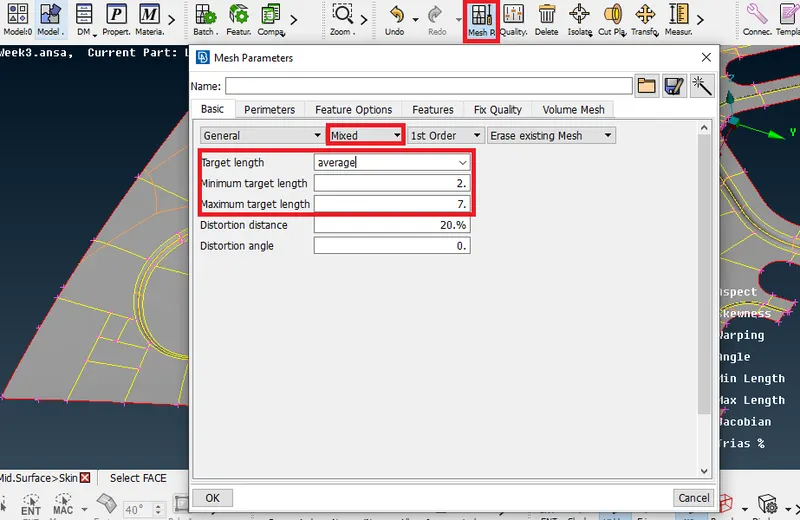
The quality criteria can be entered as follows: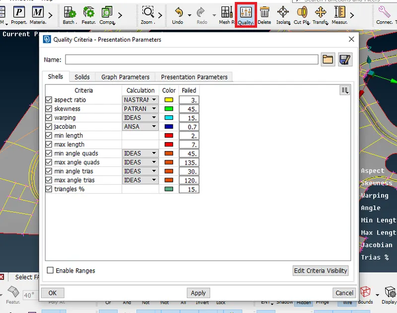
After that, we can go ahead and assign the target length. This is done by accessing the 'length' tool again from the Perimeters section under the Mesh module. We need to select the entire midsurface and assign the target length (which would be 5mm).
To facilitate better mesh flow and ensure good mesh quality, the midsurface needs further preparation with regards to proper surface cuts. This can help prevent tria formation.
Before we do that, we observe that each of these components can be separated into symmetric halves (mostly). To save on time, it's good practice to mesh half the component and reflect the mesh to generate the other half. So, we can go ahead and delete a half for each of the inner extract and outer extract components. Whereas for the hinge reinforcement, we can delete one of the two since they are mirror images of each other. The delete tool can be accessed from the top toolbar section.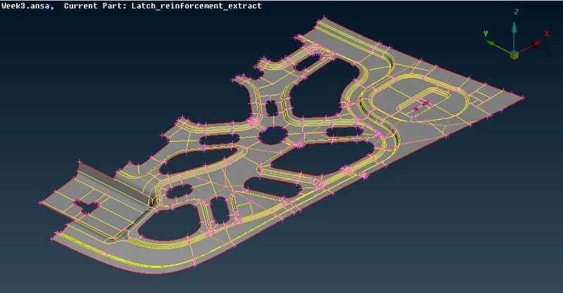
Cuts can be made using the 'Cut' tool from the Mesh module (under macros). We can go ahead and try our best to split up the surfaces to rectangular regions to ensure the least number of trias. Existing feature lines that may hinder this can also be suppressed. This is done by right-clicking the lines using the same 'cut' tool.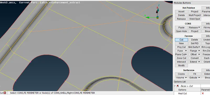
In other cases, this needs to be carried out to prevent minimum length failure. The most famous example of this in the hood component would be that of the hemming region of the outer extract panel. The feature lines on either side of the hemming peak need to be suppressed to prevent element failure.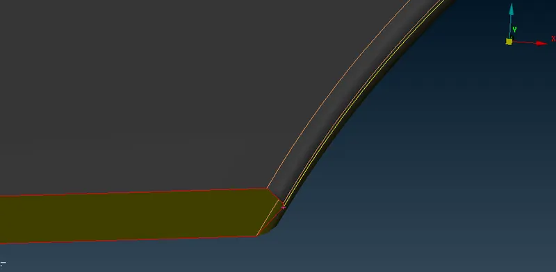
Now lets see how to remove tria
After preparing the surfaces, we can go ahead and mesh them. We need to use the 'best' mesh option, which can be accessed from the 'Mesh Generation' section. It's good practice to start from an inner region of the component with free edges (single cons) and mesh the surrounding regions in an outward direction. For example: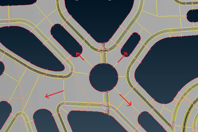
After meshing a region, analyze the mesh and see if it can be improved. If it can be improved, we can make use of the 'Reconstruct' tool from the Shell Mesh section in the mesh module. It basically remeshes the selected mesh keeping the quality criteria in mind and tends to produce a better mesh. The tool gives the option to rerun the tool so we can ensure the produced mesh is up to the standards we are looking for.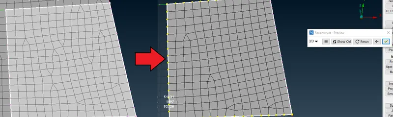
This process is repeated until we mesh the entire component.
Mesh quality can be checked by switching to hidden mode. The option is available on the bottom toolbar. The failing elements will be highlighted in the colours as per the legend on the side of the screen (of the quality criteria).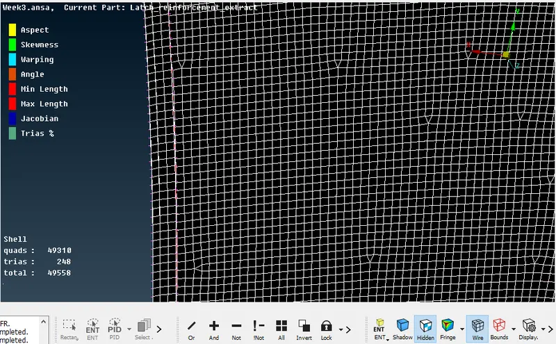
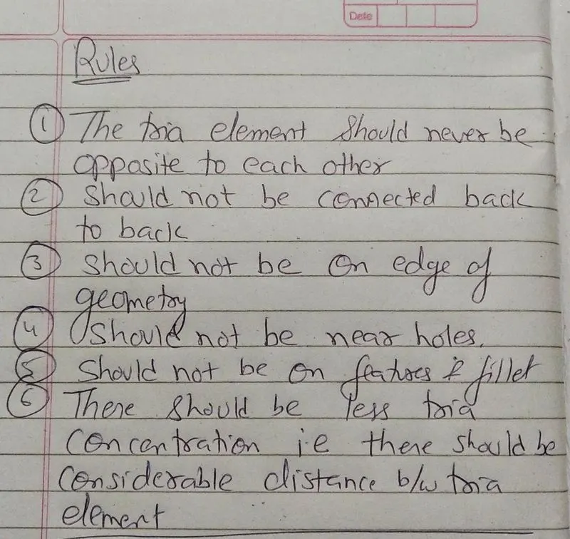
Sometimes, the reconstruct tool doesn't work in getting rid of some trias. Trias are okay but certain types of trias need to be avoided - like opposite trias or trias touching feature lines. Trias can be worked on using the swap, split, join and smooth tools. The first three are available in the 'Elements' section and the smooth tool is available in the 'Shell Mesh' section.
In the following example, there are trias touching each other and in close proximity:
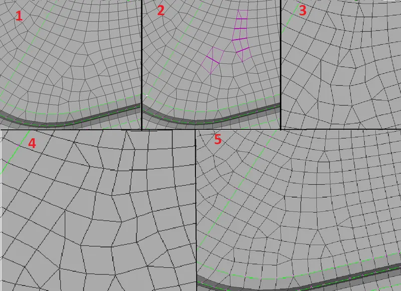
In (2), the splits are created [as can be seen in (3)]. The adjoining trias are joined in (4) and all the surfaces are smoothed in (5).
The opposite trias are taken care of by splitting the quads between them using the split tool, then joining the two adjoining trias formed (involving the opposite trias) using the join tool. The resulting mesh can then be smoothed using the smooth tool to improve the mesh flow.

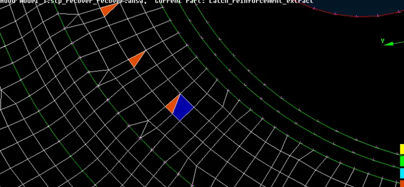
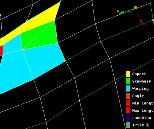
here in both the figures we can see that multiple color came which signifies according to legend itself given in hidden mode this I have removed by split and sometime paste option & then doing smooth.
After all the regions to be meshed have been meshed, we can go ahead and work on transforming the component to produce the symmetrical region to complete the mesh for the entire component. This can be done by accessing the 'transform' tool from the top toolbar and selecting 'copy'. We can then select the entities that need to be symmetrically replicated. After that, we can move on to the next window and go to the symmetry tab and proceed without changing any of the options.
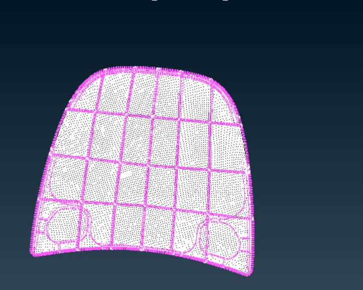
Now we have sucessfully done meshing , we will see physics behind why to choose mid surface
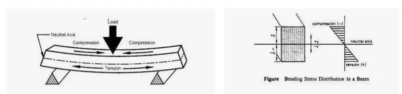
Here we can see that upper face is compressive in nature while lower face is tensile in nature hence if we do meshing on any ony of surface it will fails because of stress concentration , but neutral axis have no effect on it , also we can see graph (RHS) from there we can conclude that neutral axis is at origin i.e zero