Week 2 Railwheel and Track
Objective 1: Compare the results (Total deformation, Equivalent (von-mises) stress, Equivalent elastic strain) of rail track wheel simulation for bearing load 1e5 N and 5e5 N.
Objective 2: Compare the inbuilt total deformation with user defined total deformation for bearing load of 1e5 N.
Numerical Setup:
Step 1: Import CAD geometry of Railwheel solid model.
Step 2: Insert structural steel as material as shown in figure 1.
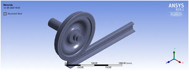
Figure 1 CAD model of rail wheel model and insertion of structural steel as material.
Step 3: Define contacts. Frictional contact is defined between running rail and wheel as shown in figure 2. Frictionless contact is defined between wheel and shaft as shown in figure 3.
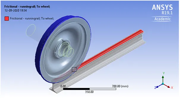
Figure 2 Defining a frictional contact between rail and wheel.
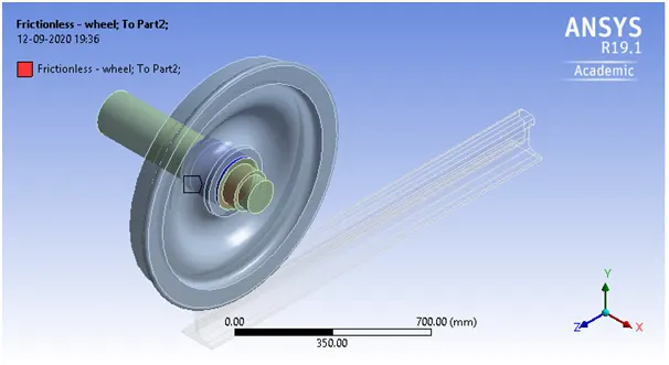
Figure 3 Defining a frictionless contact between wheel and shaft
Step 4: Then joint are defined. Fixed joint between ground and running rail is defined as shown in figure 4. Translational joint is defined between ground and shaft as shown in figure 5. Planar joint is defined from ground to wheel as shown in figure 6.
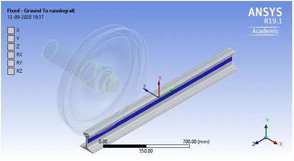
Figure 4 Defining a fixed joint from ground to rail.
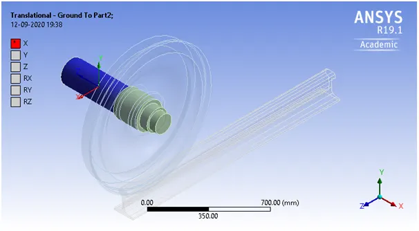
Figure 5 Defining a translational joint from ground to shaft.
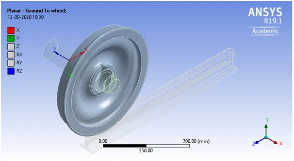
Figure 6 Defining a planar joint from ground to wheel.
Step 5: Then tetrahedral mesh is defined as shown in figure 7. A element size of 35mm is given. The generated mesh has the 17929 nodes and 9203 elements. In analysis setting The Number of steps is given 5 with the step end time as 1sec. The auto time stepping is given program controlled. The Solver type is given direct. The weak springs are off with the large deflection on.
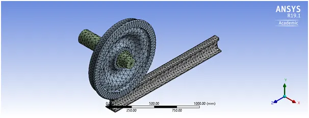
Figure 7 Defining tetrahedral mesh of element size 35mm.
Step 6: Then a bearing load of 1e5N (5e5N for case1) and displacements for shaft are defined as shown in below figures 8,9,10.
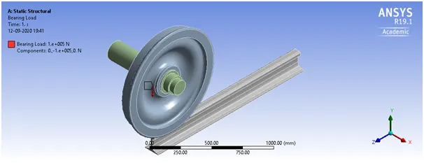
Figure 8 Defining a bearing load of 1e5 N in –Y direction.
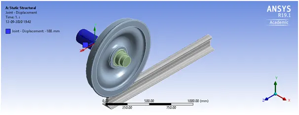
Figure 9 Defining a joint displacement of 100mm in global –Z direction.
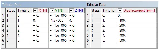
Figure 10 Tabular data for bearing load of 1e5 N and joint displacement of 100mm for each time step.
Step 7: Then solution result parameters Total deformation, Equivalent elastic strain, Equivalent stress, Contact tools, Force reaction, User defined result angle translated (RX) and Total deformations (sqrt(UX^2 +UY^2+ UZ^2)) are defined as shown in below figure 10. Then simulation is run in the quest of above parameters.
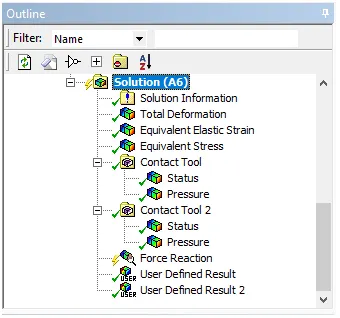
Figure 11 Solver result parameters setting.
Solutions
Solution for case 1: The total deformations as shown below for the two cases bearing load 1e5 N and 5e5 N are same as shown in figures 12,13,14.
The total defomrations are highest on upper side of the wheel and lowest on the rail.
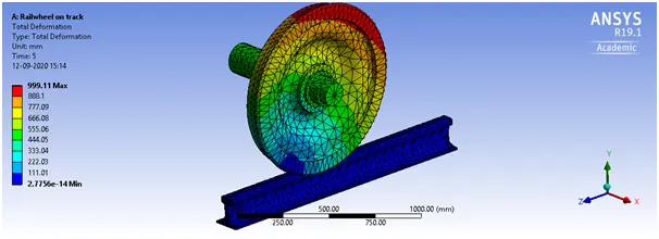
Figure 12 Total deformations for case with bearing load of 1e5N.
Figure 13 Total deformations for case with bearing load of 5e5N.
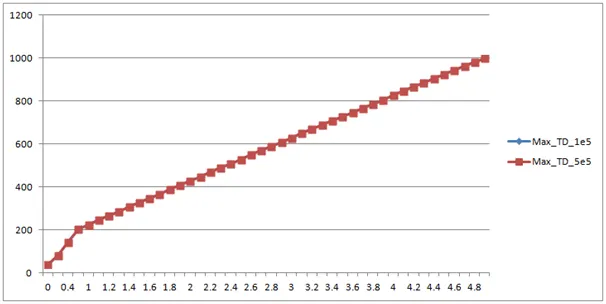
Figure 14 Max total deformation for each time step of simulation.
The equivalent stresses are around 4 times higher in case with bearing load 5e5 N, as shown in below figures 15,16,17. The maximum eq. stress is 129.38 MPa in case of bearing load 1e5 N whereas in case when bearing load is 5e5N, the maximum eq. stress is 497.33 MPa which is 3.84 times higher.
The equivalent stresses are below 15 MPa for almost complete wheel, complete shaft and complete rail.
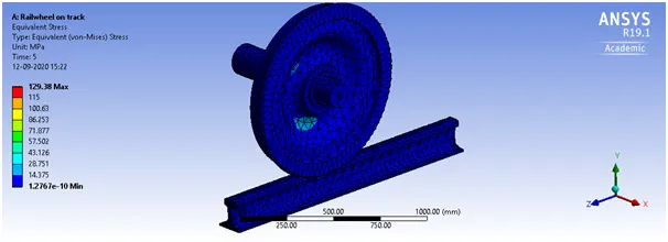
Figure 15 Equivalent(von-mises) stresses for case with bearing load of 1e5N.
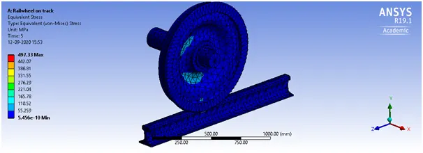
Figure 16 Equivalent(von-mises) stresses for case with bearing load of 5e5N.
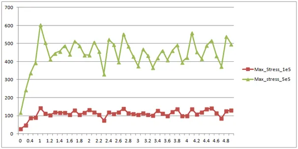
Figure 17 Max eq. stress for each time step of simulation.
The equivalent strains are also almost four times higher than in case of bearing load 1e5 N as shown in below figures 18,19,20. The maximum eq. elastic strain is 0.0069116 in case of bearing load 1e5 N whereas in case when bearing load is 5e 5N, the maximum elastic strain is 0.0026162 which is 3.78 times higher.
The equivalent strains are below 7.6796e-5 for ammost complete wheel, complete shaft and complete rail.
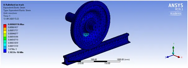
Figure 18 Equivalent elastic strains for case with bearing load of 1e5N.
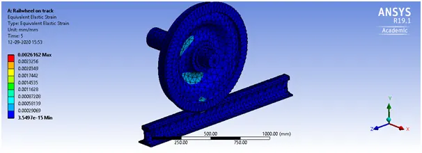
Figure 19 Equivalent elastic strains for case with bearing load of 5e5N.
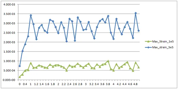
Figure 20 Max eq. elastic strains for each time step of simulation.
Solution for case 2 : The total deformations for the bearing load 1e5 N are found to be same using inbuit solution and user defined solution (=sqrt(UX^2+ UY^2+ UZ^2)) as shown in below figures 21 and 22.
Figure 21 Total deformations for the bearing load 1e5 N by inbuilt solution
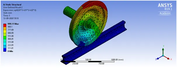
Figure 22 Total deformations for the bearing load 1e5 N by user defined solution