Week 2 Railwheel and Track
OBJECTIVES
To Perform a static structural analysis on the Rail wheel and Track setup
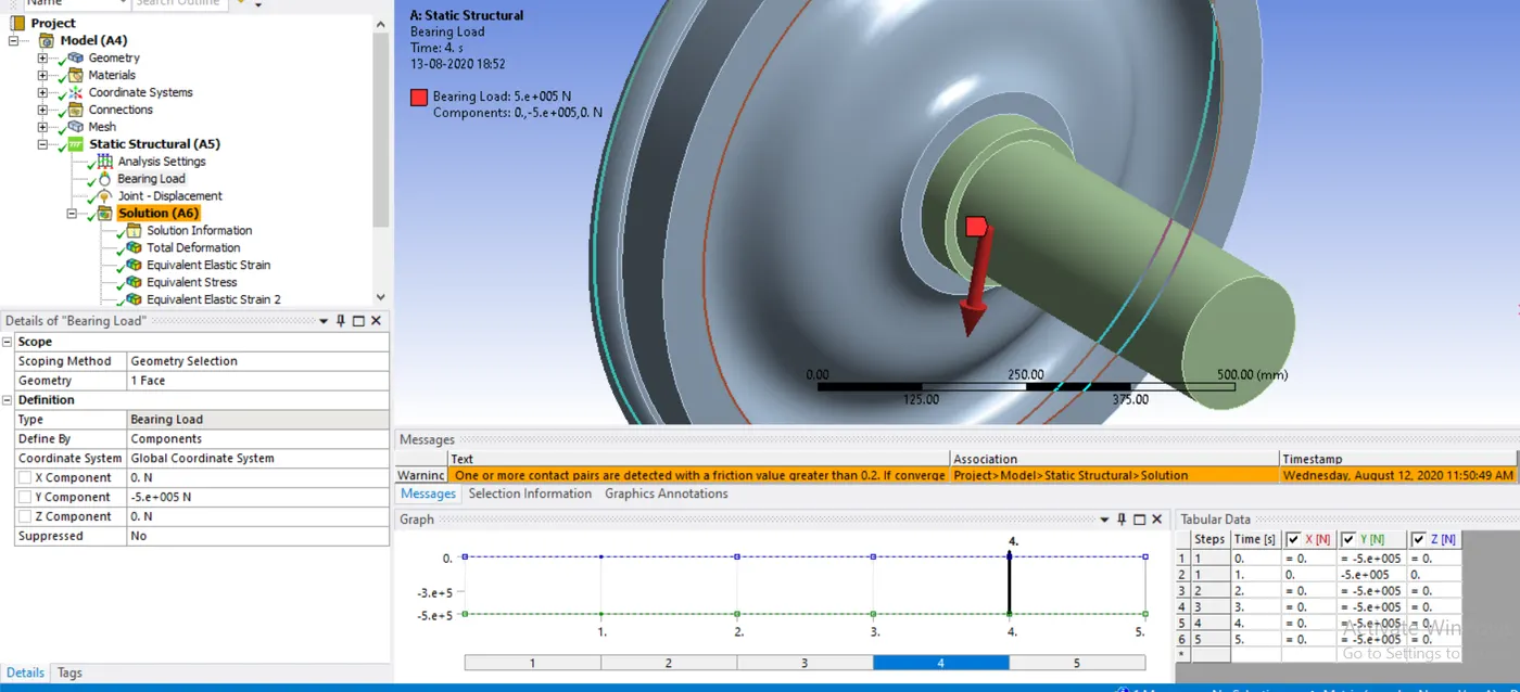
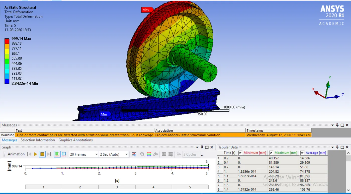
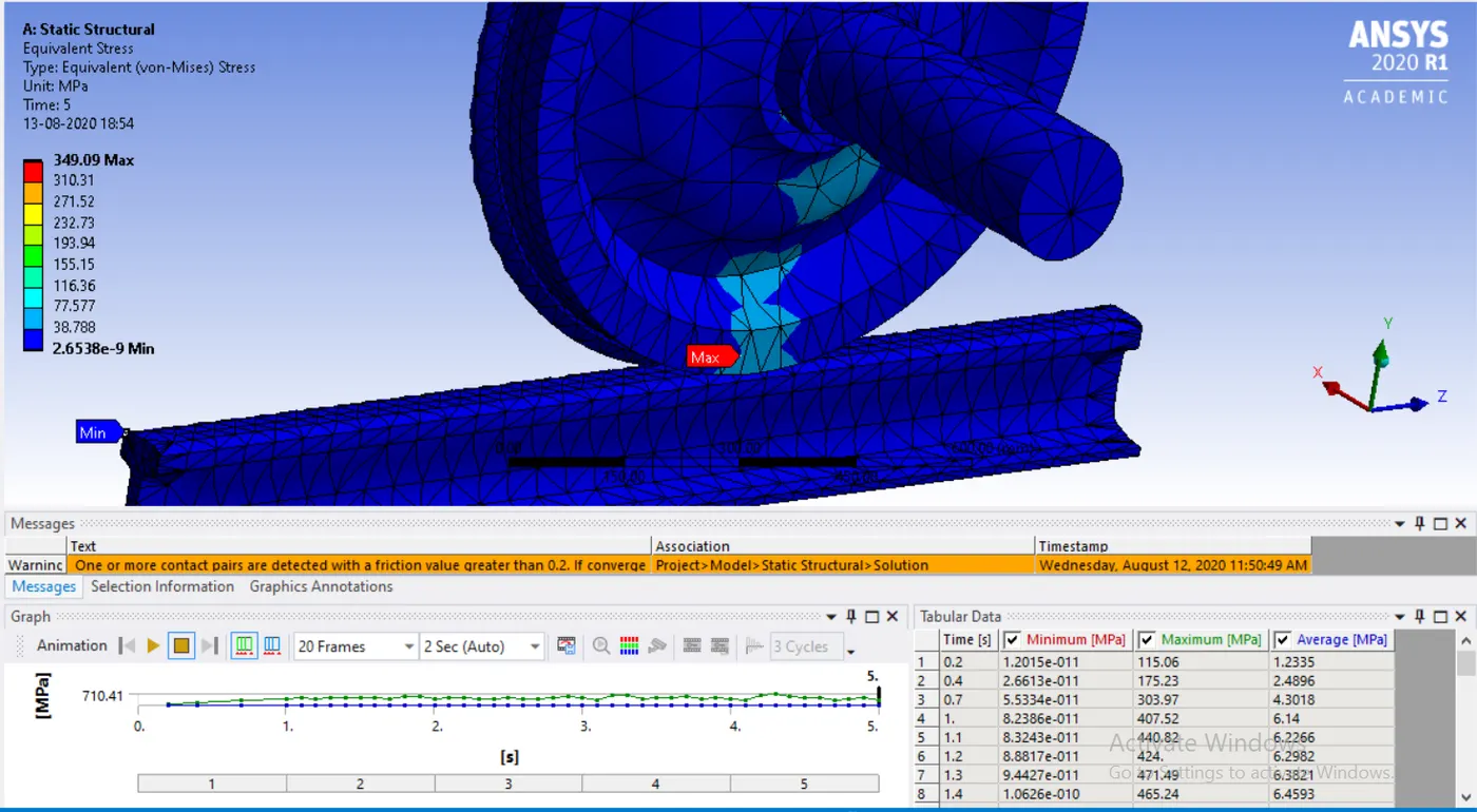
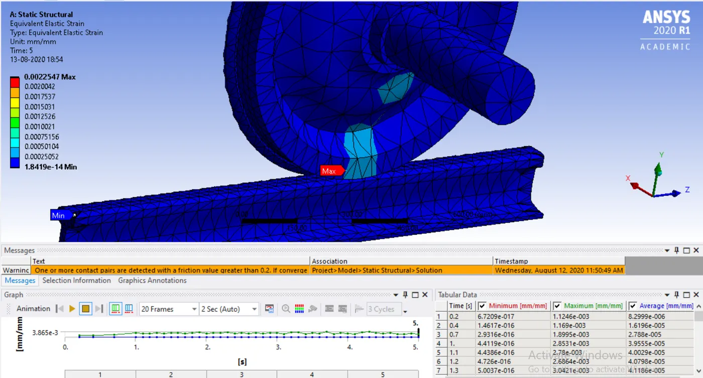
Case 1: Multiply the bearing load by 5 times and compare the results with the load of 100000 N (As done in week 2 video). Compare the Total Deformation, Equivalent stress and the life under both the loads
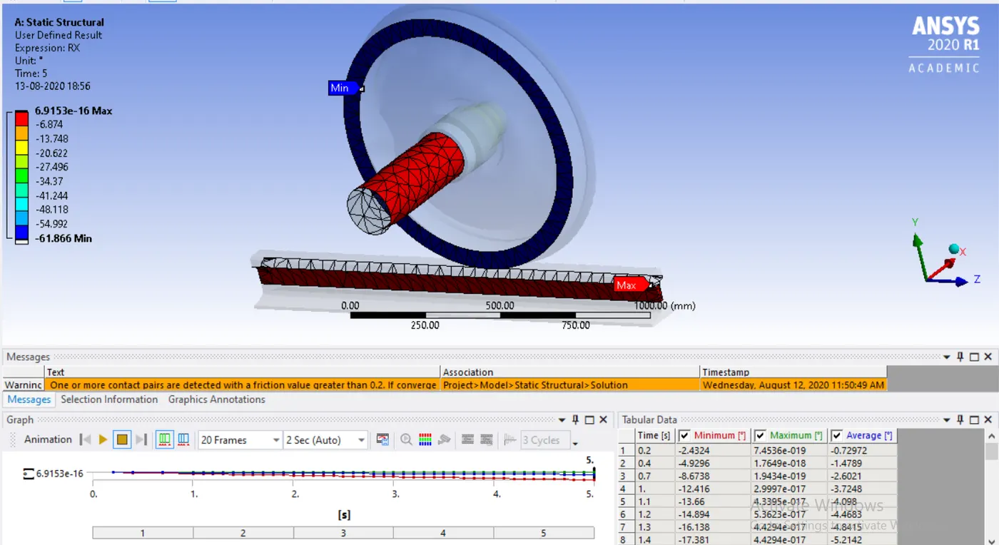
Case 2: Implement a User defined result and calculate the Total Deformation from this result and check if it is the same as that obtained by the inbuilt result by ANSYS for a load of 100000 N.
PROCEDURE
- Assign the material in engineering data or create if new material needed.
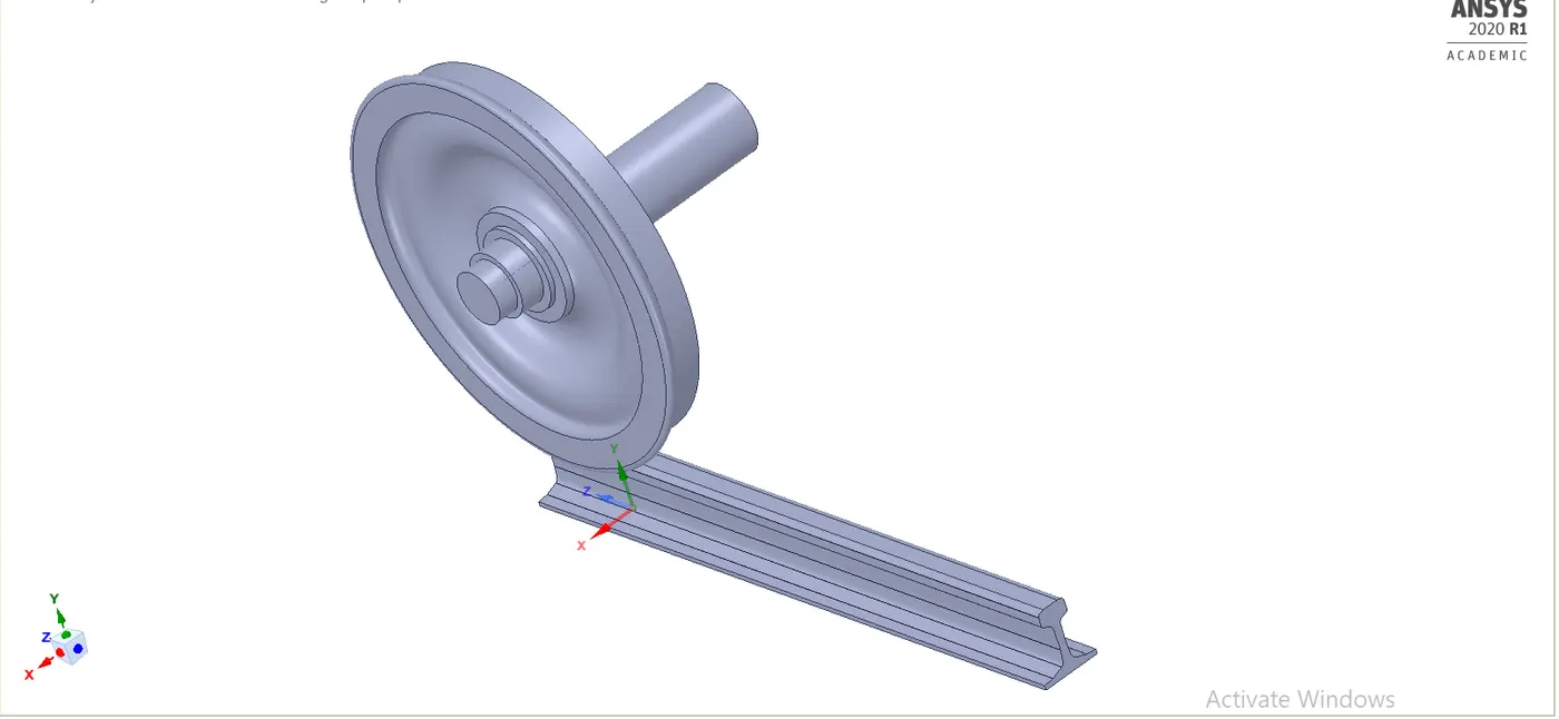
- Then import the model into ansys by opening it in space claim.
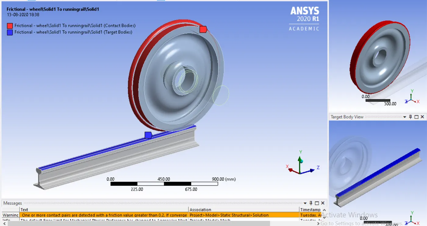
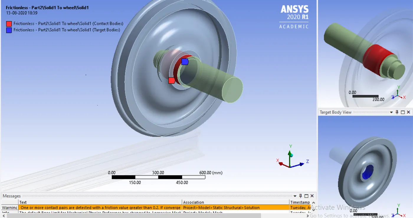
- Give the contact between the wheel, rail and shaft. Define the contact between rail and wheel as frictional and wheel and the shaft as frictionless.
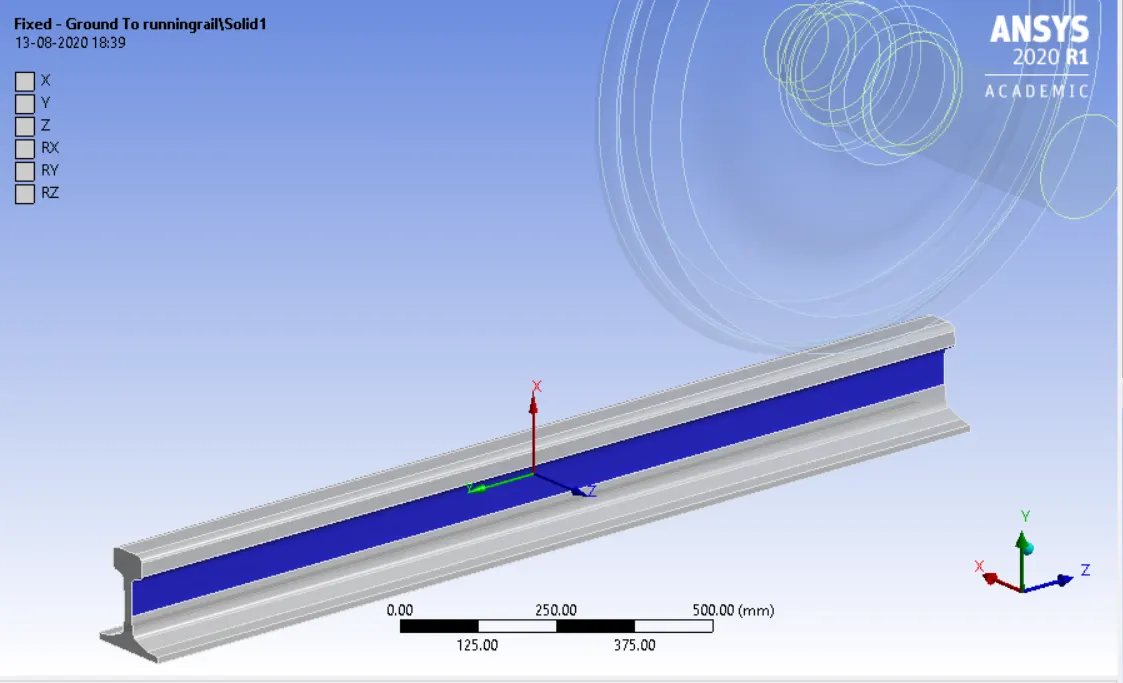
- Then create joints for the components. Fixed joints on the rail, translate joint on the shaft and planar joint on the wheel.
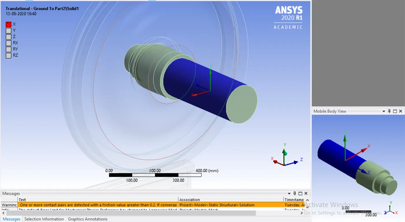
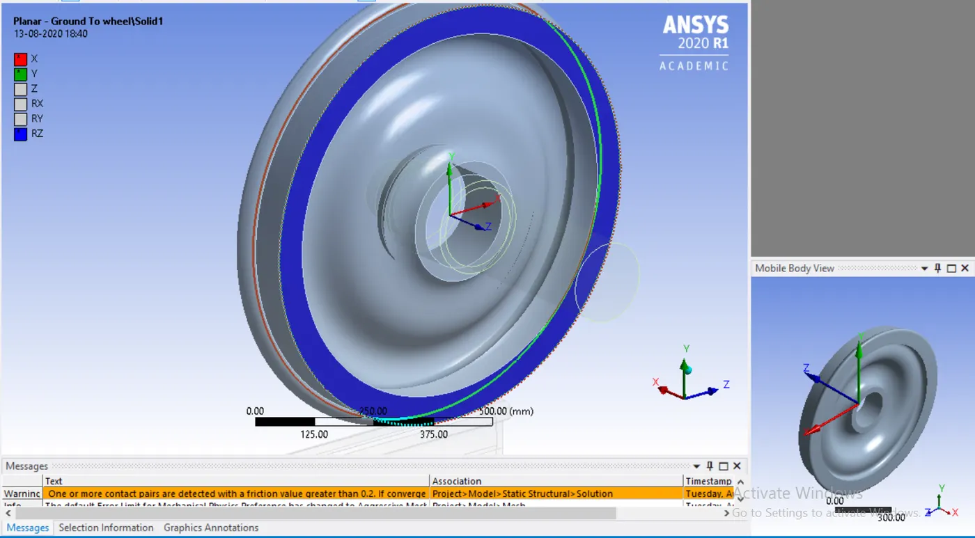
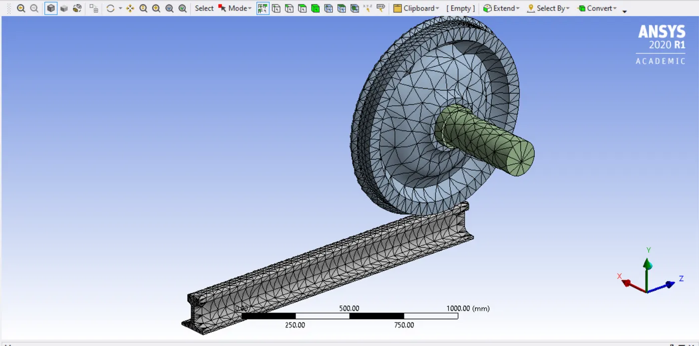
- Then mesh the components with required mesh size as 50 and redefine the mesh with finer mesh of 35 on the faces of wheel and rail.
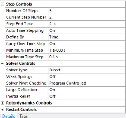
- Then define the required parameters in analysis setting.
- Then create joints load as displacement and assign required distance.
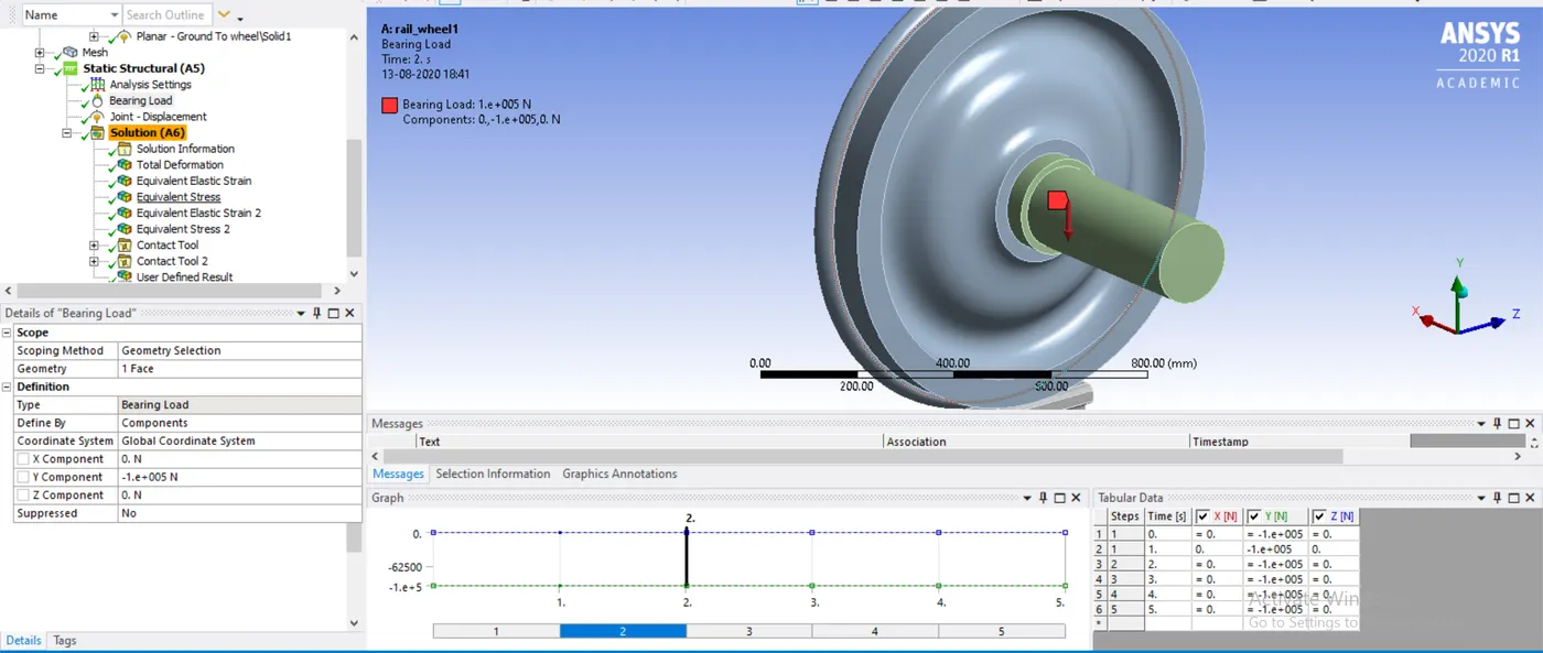
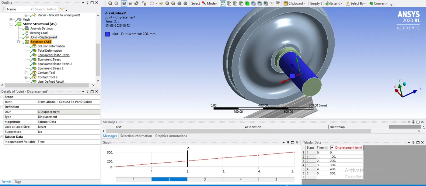
- Then create bearing load on the id of the wheel.
RESULTS
Case1
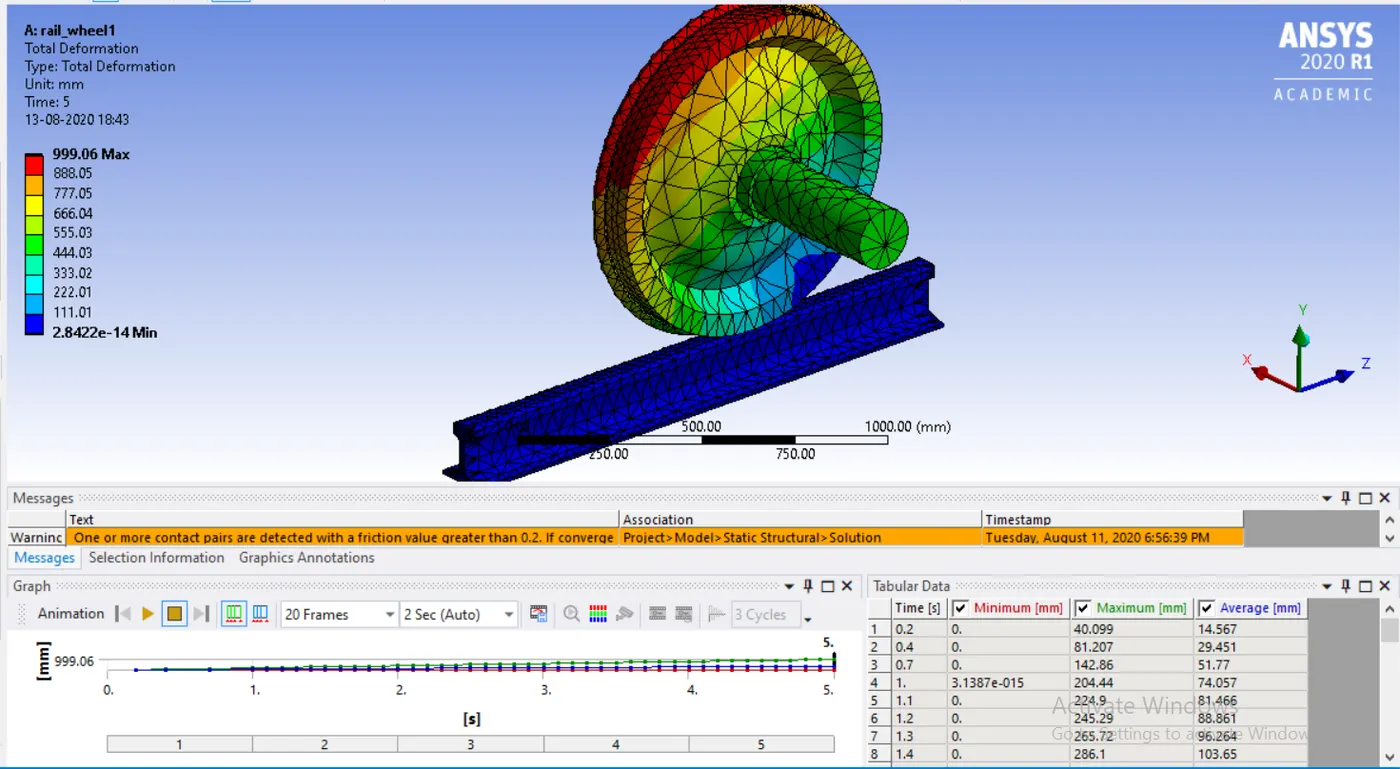
Total deformation
Equivalent stress
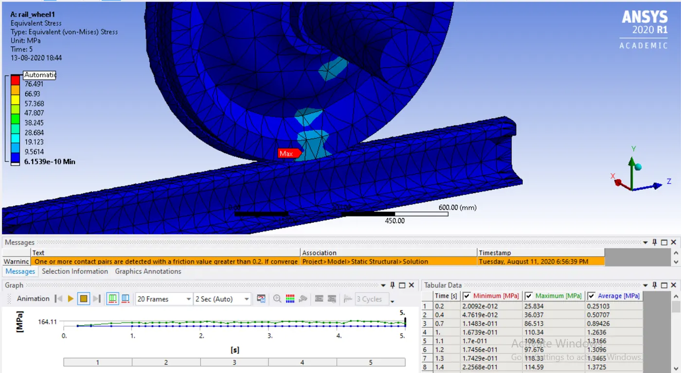
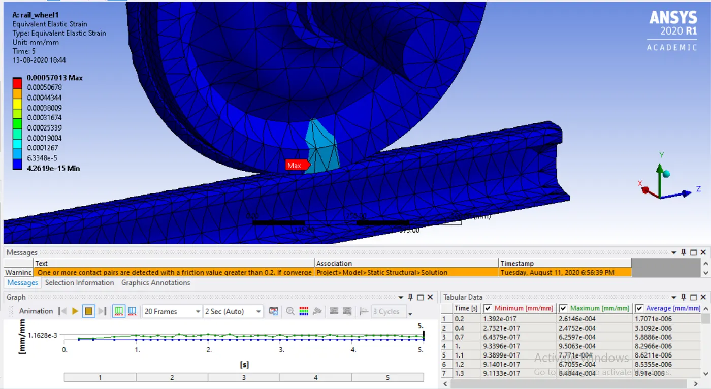
Equivalent strain
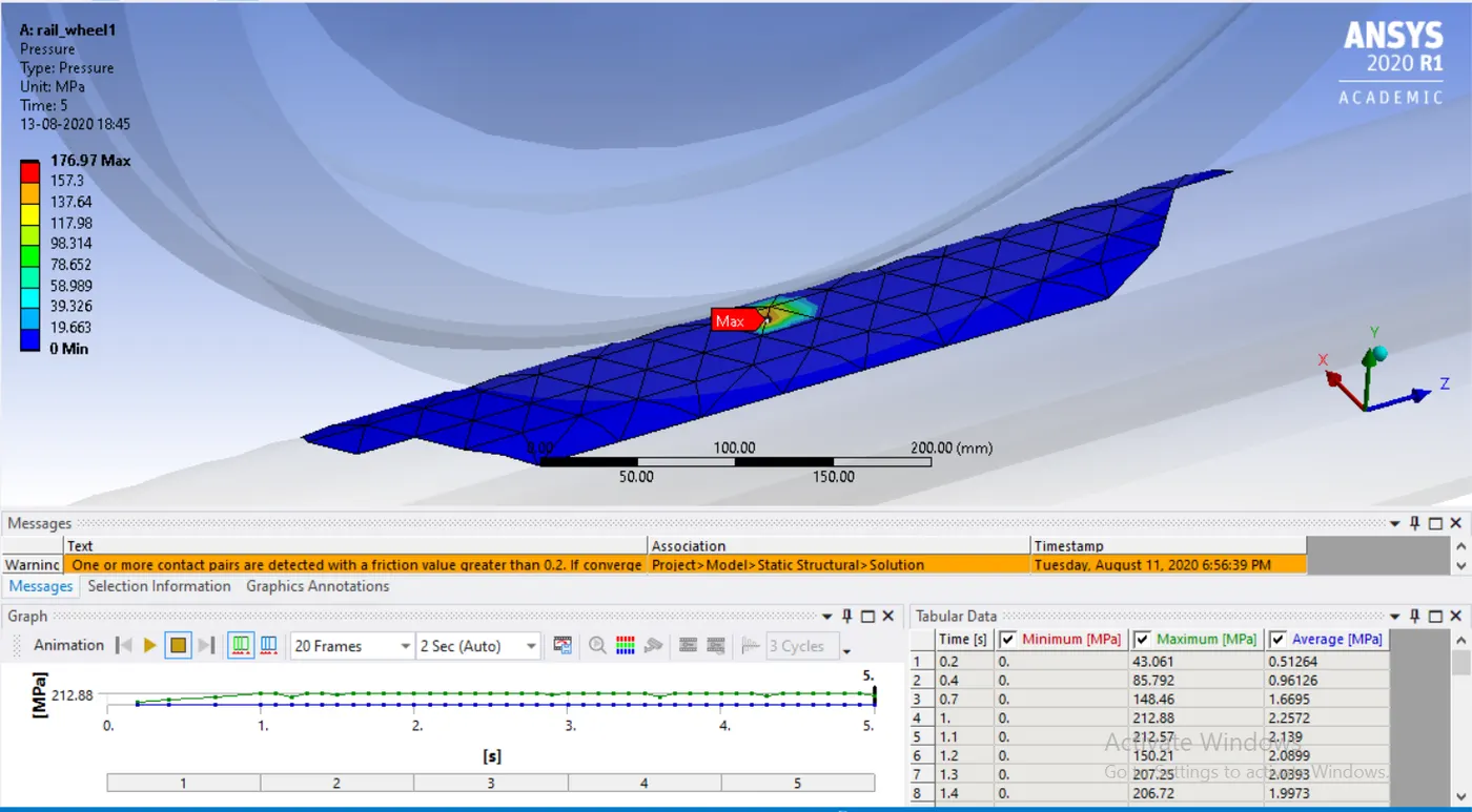
Pressure
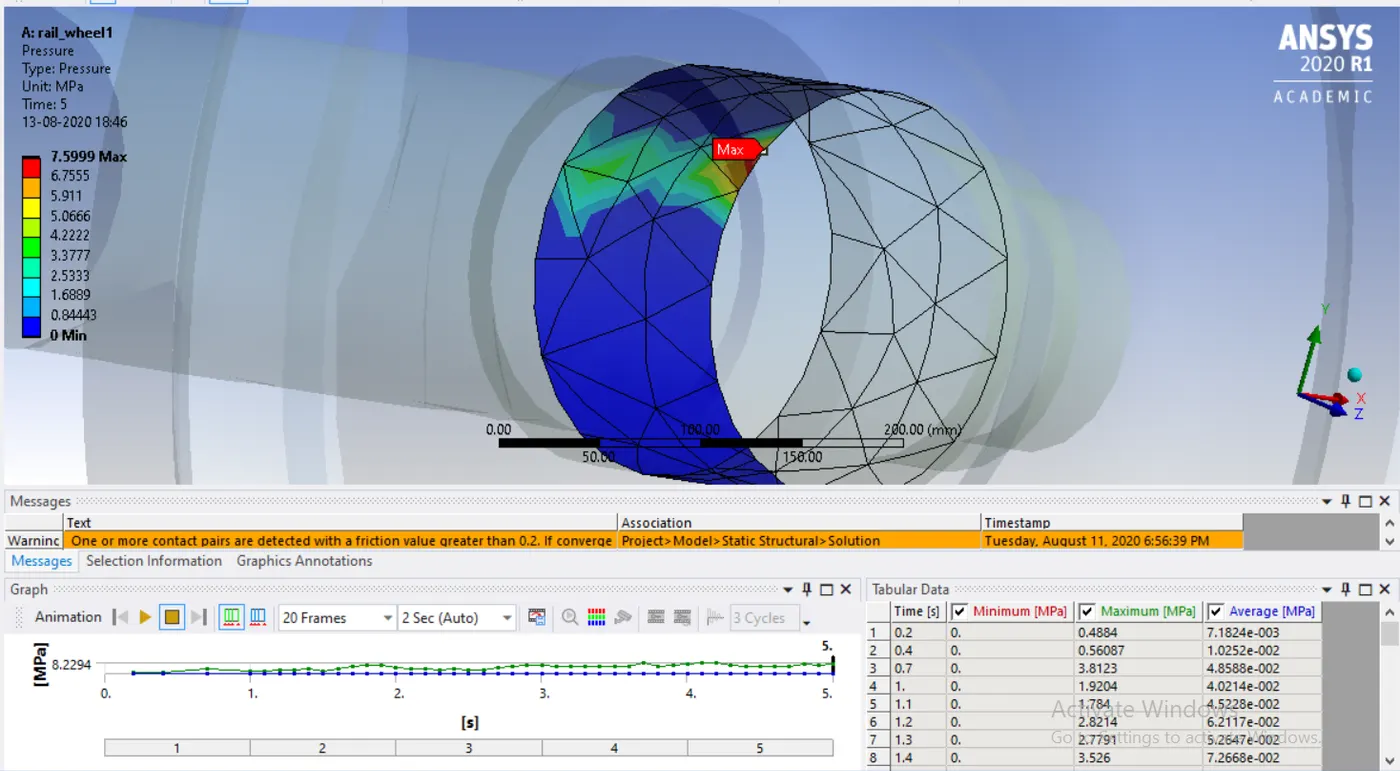
User Define
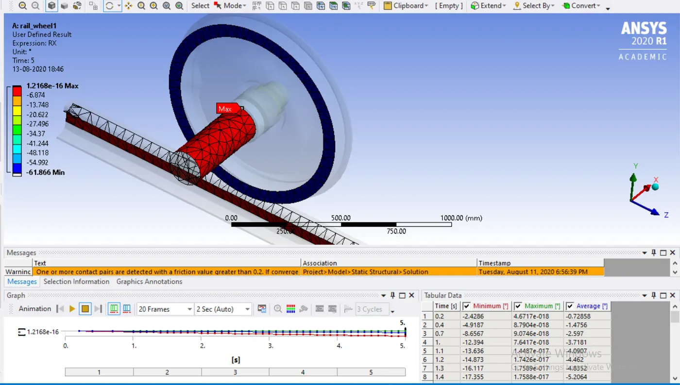
Case2
Total deformation
Equivalent stress
Equivalent strain
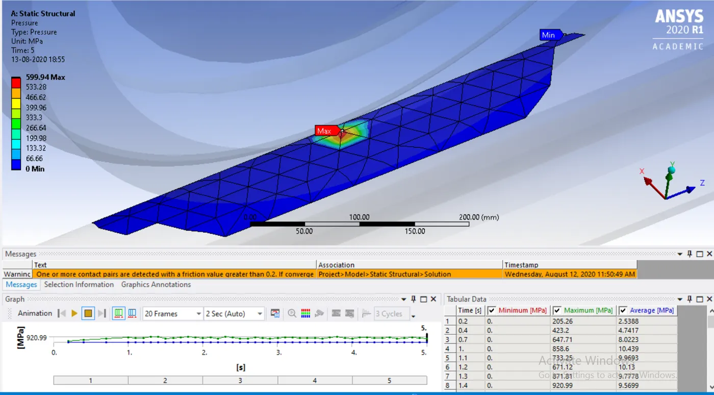
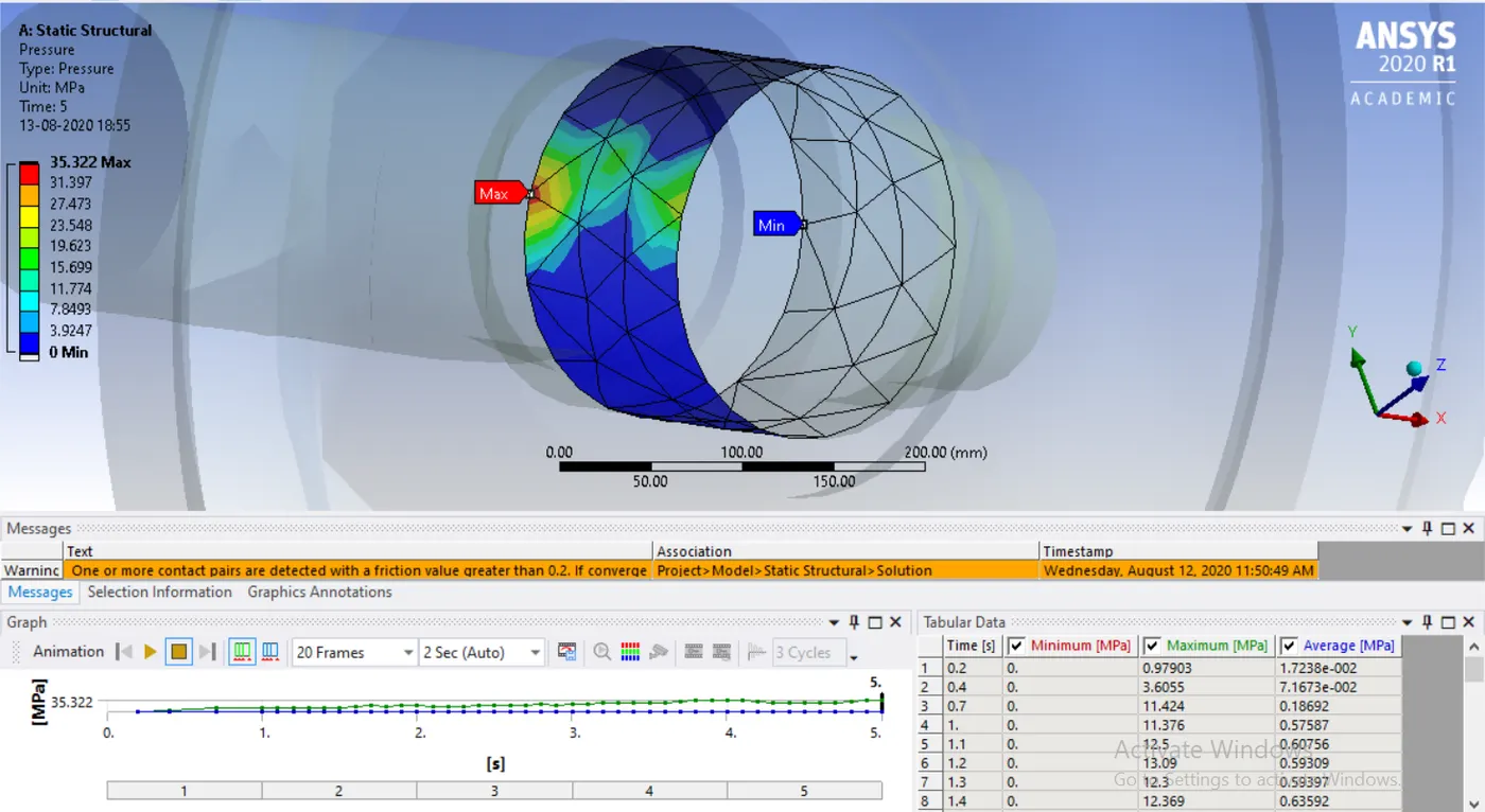
Pressure
User Define
CONCLUSION
| Total deformation (mm) | Max Equivalent stress (MPa) | Max Equivalent strain | contact pressure at rail (MPa) | contact pressure at bearing (MPa) | |
| Case1 1e+5N | 999.09 | 84.49 | 5.5e-4 | 176.87 | 7.599 |
| Case2 5e+5KN | 999.14 | 349.09 | 22.2e-4 | 599.94 | 35.322 |
As the table denote that the stress, strain and contact pressure is more in case2 because the bearing load is 5 times more than the case 1.
but by the life the material assign is suitable for both the load cases.