Week 2 Railwheel and Track
Objective: In this study Railwheel track analysis has done. The solution is compared with bearing load at 100000N and 500000N. The outcomes results are Equivalent stress , strain, total deformation and life This study is done in Ansys 2022
Introduction:
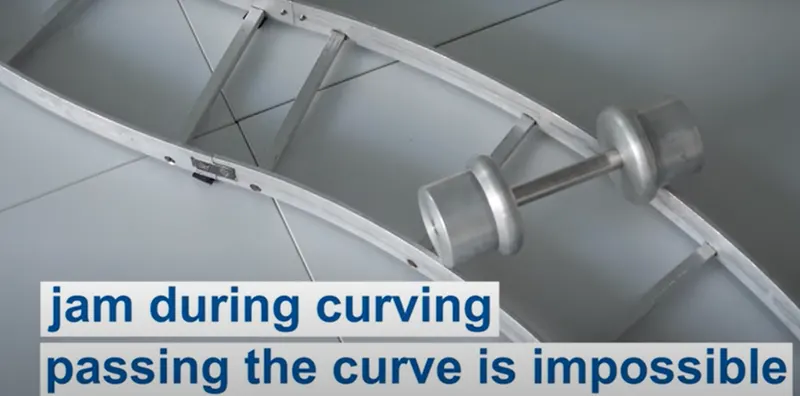
As per design purpose Railwheel does not design as a cylindrical shape because wheel can jam on railway track during the curve direction track shape
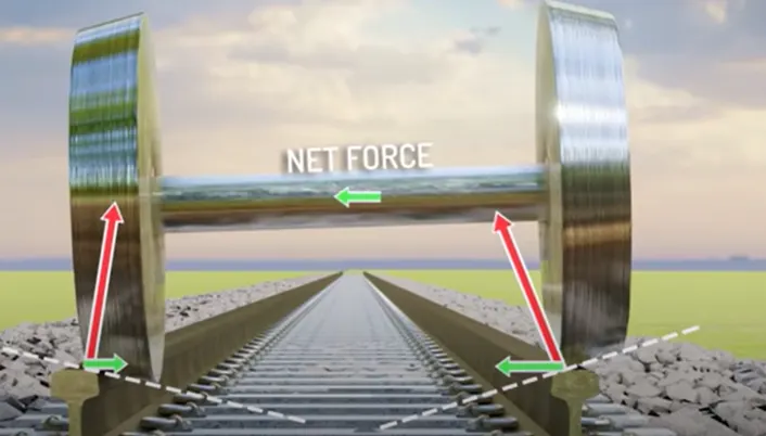
So Designer design the wheel in conical shape , 1st reason for centralized movement of wheel axle in respect to railway track as in below figure suppose axle goes toward right side then net force (due to horizontal component of reaction force at contact of wheel and track) shift the axle other side, so by this way axle wheel remain centralized track
2nd reason, flanges avoid jam condition(differential action) at curve track , so the wheel designed as a conical shape. To understand let see below figure, wheel travels more distance.
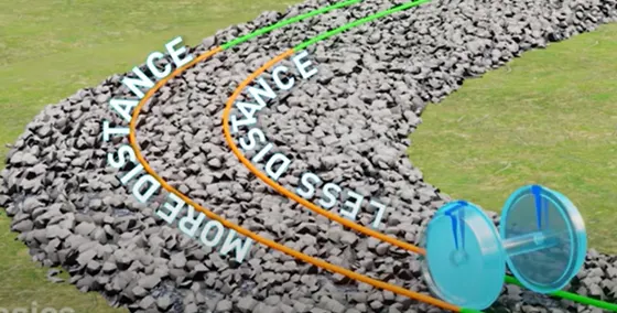
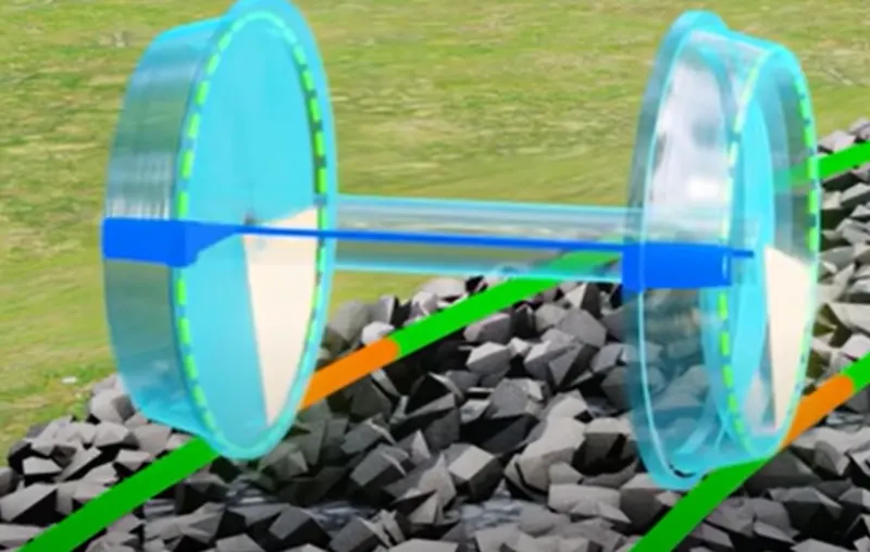
The wheel travels large distance because suppose during the changing direction on curved track ,left wheel slides toward left side and also right wheel due to centrifugal force and then at that condition left wheel have large radius of rotation as compare to right side wheel (because now at that point right wheel has less contact radius at the track due to conical shape of wheel) so more radius will have to cover more distance for same amount of speed.
Modern track typically uses hot-rolled steel with a profile of an asymmetrical rounded I-beam. Unlike some other uses of iron and steel, railway rails are subject to very high stresses and have to be made of very high-quality steel.
Procedure:
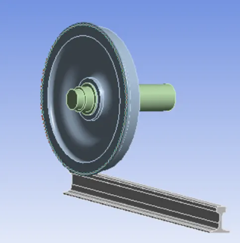
1.Geometry
- Input the model as Step format in geometry
2.Material assignment
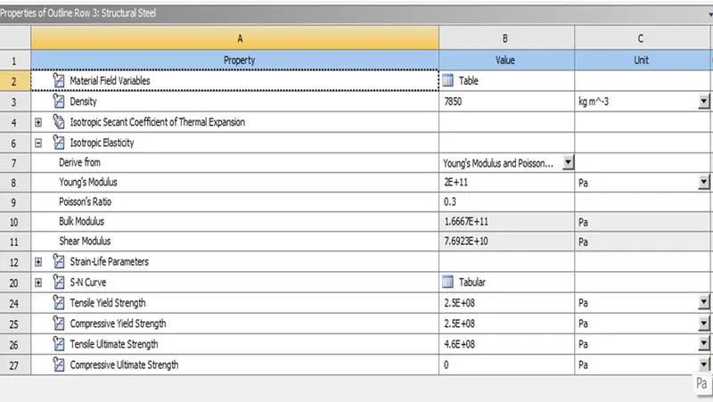
- Open Engineering Materials and select the required material.
- Structure steel is used as material in ANSYS of given material:
3.Meshing
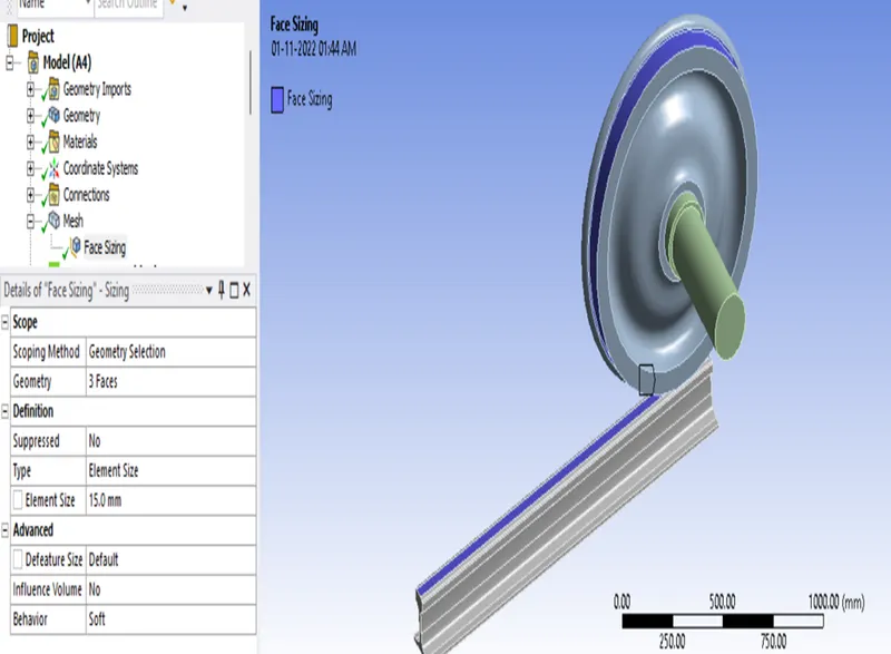
- For Meshing the body element size =20mm
- For Contact surface meshing = 15mm
4.Boundary condition
Connection
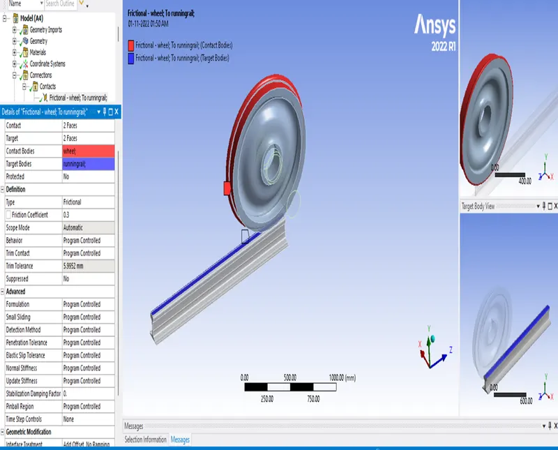
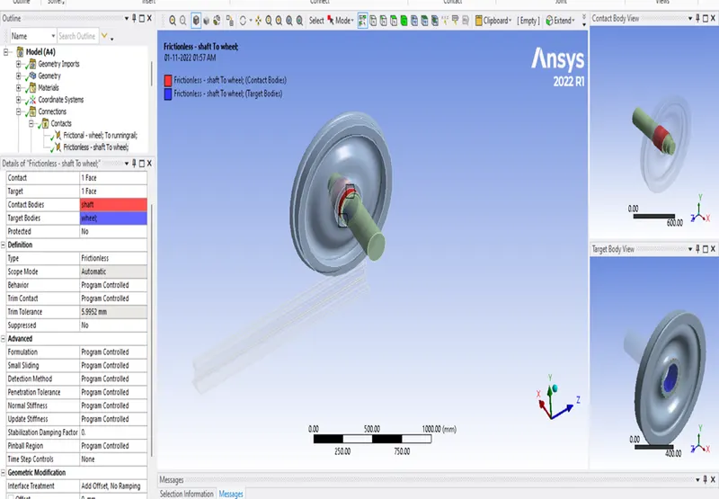
1.Contact creation
(a)
- Select the faces of gear teeth which will be in contact during simulation running
- Definition > type - Frictional
- Advanced > Formulation - Program controlled
- Geometric Modification > Interface Treatment - Add offset Not ramping
(b)
- Select the faces of gear teeth which will be in contact during simulation running
- Definition > type - Friction less
- Advanced > Formulation - Program controlled
- Geometric Modification > Interface Treatment - Add offset Not ramping
- Joint creation
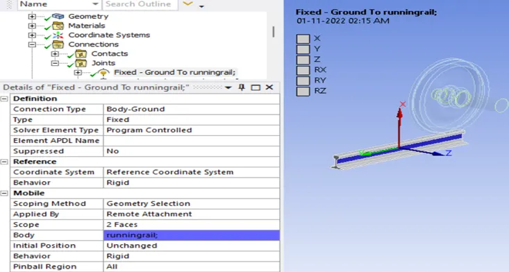
(a)
- Create joint for running rail by Connection > Right click on it > Select joint
- Connection Type- Body Ground
- Type- Fixed
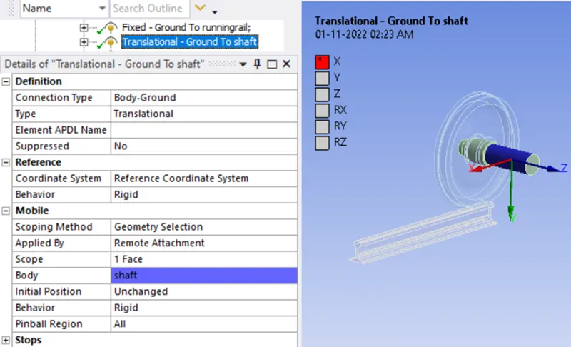
(b)
- Create joint for shaft by Connection > Right click on it > Select joint
- Connection Type- Body Ground
- Type- Translational
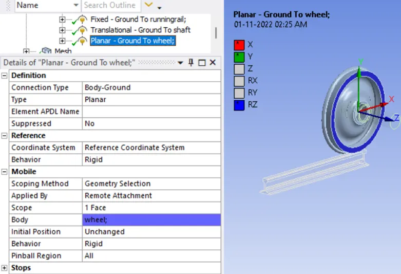
(c)
- Create joint for wheel by Connection > Right click on it > Select joint
- Connection Type- Body Ground
- Type- Translational
3.Analysis Setting
(a)
- Apply number steps= 1
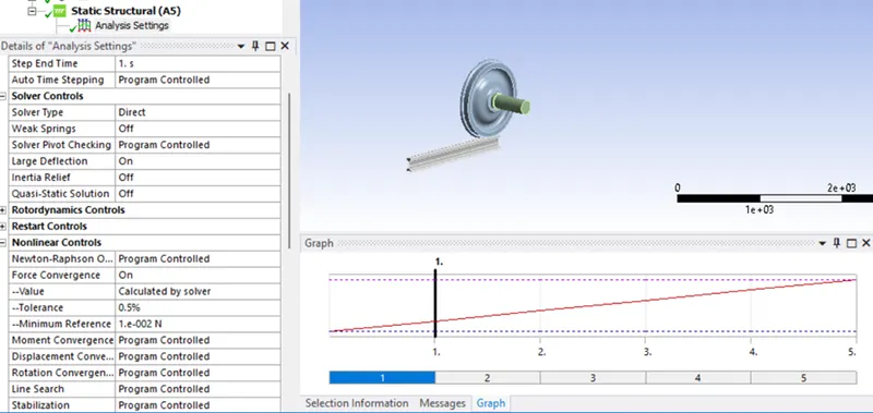
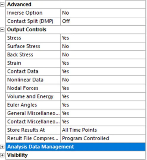
(b)
- Apply number steps= ( 2 to 5 )
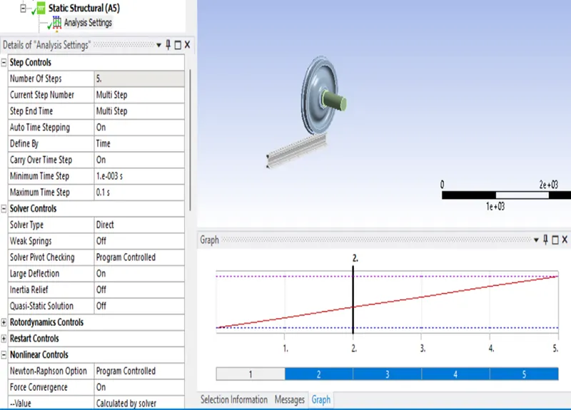
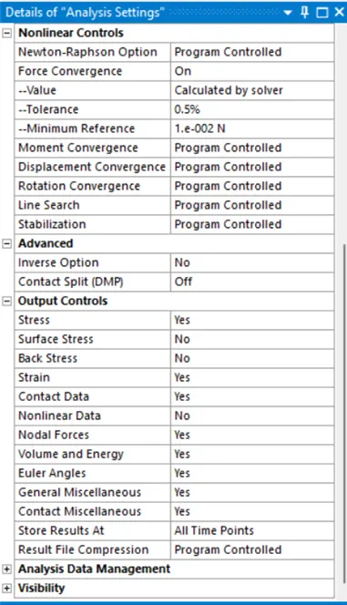
Insert different load by right click on analysis setting
- (a) Insert bearing load with Definition > Type- Bearing load
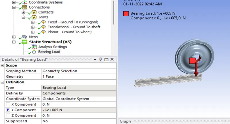
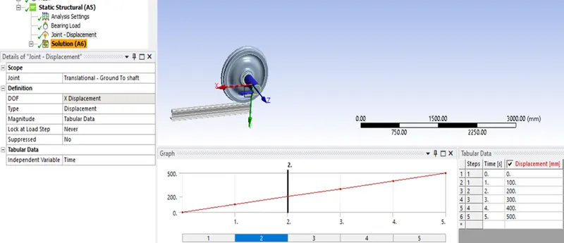
Insert joint load by right click on analysis setting
- (b) Insert joint load with Definition > Type- Displacement (500mm with tabular data)
Results (output):
Mesh
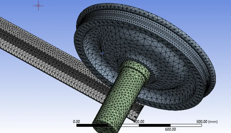

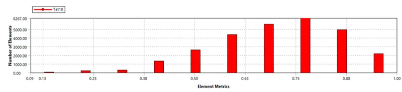
Meshed Quality: According to mesh matrics the Quality vary from 0 to 1
0 for poor Quality element
1 for best Quality element
In our case Mesh of maximum element lies in between 0.7 to 0.9 so it is good as per Quality scale
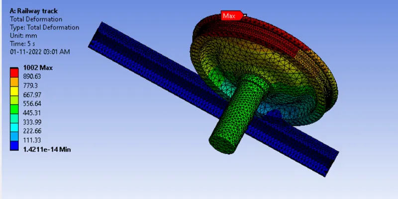
Deformation
Max deformation= 1002mm
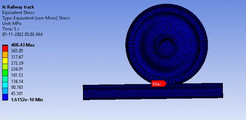
Stress
Max stress= 408.43 Mpa
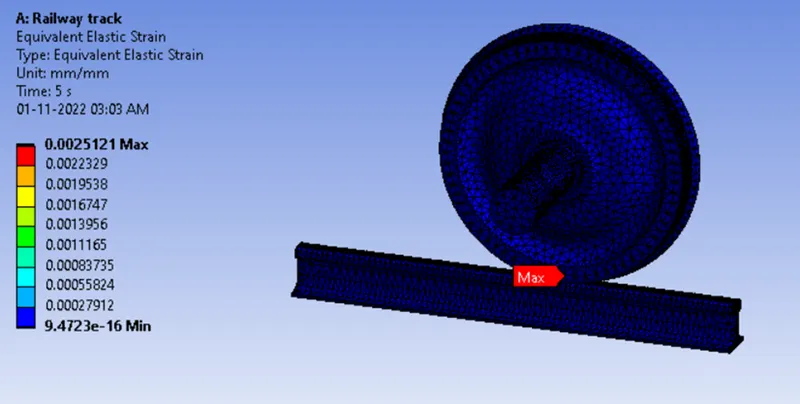
Strain
Max Strain =0.0025121 mm/mm
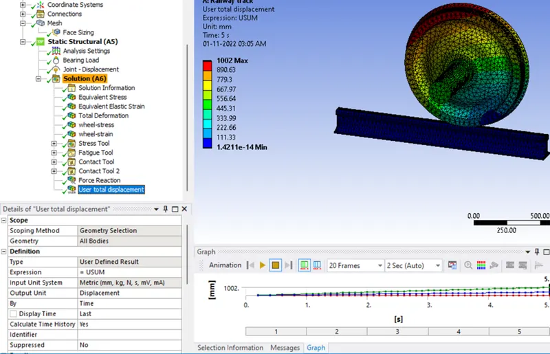
Total deformation (User defined)
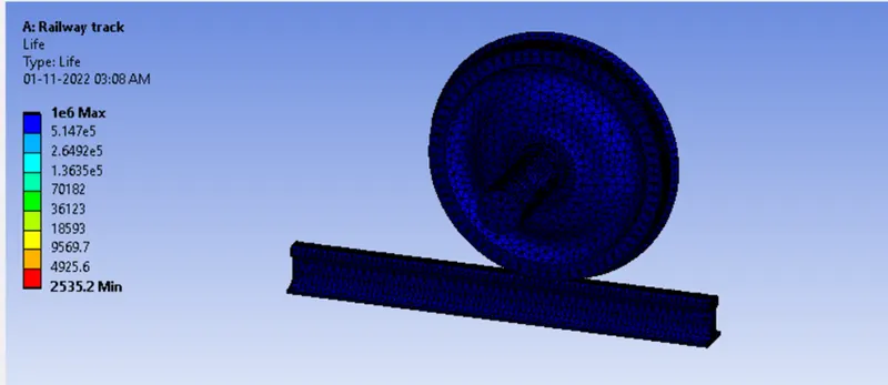
Life cycle result
Minimum = 2535.2 cycles
Now compare these results for different bearing load by parametric study by selecting the P symbol as above results which will required for comparing
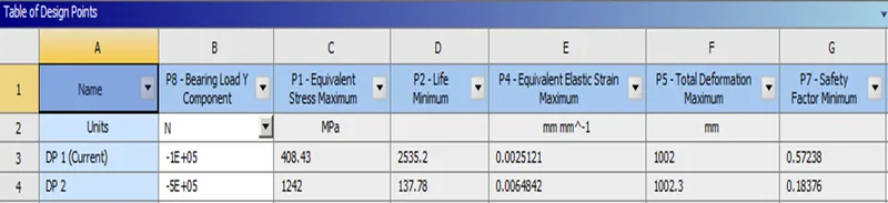
Conclusion:
By comparing the result, the study shows that deformation result and strain result has negligible change but stress result shows the considerable change ,with increased load the factor of safety and minimum life cycle reduced and tend toward the fail condition. So, it is suitable not to put load beyond that limit because beyond it, dangerous accident can be happen.