Week 2 Railwheel and Track
OBJECTIVE: The objective of this challenge is to perform a static structural analysis on the Railwheel and Track setup and to Compare the Total Deformation, Equivalent stress and the life under the two bearing loads such as 100000N and 50000ON respectively. And also to implement a user defined result and calculate the Total Deformation from this result and to compare the Total Deformation that obtained by the inbuilt result by ANSYS for a load of 100000 N.
INTRODUCTION: A train wheel or rail wheel is a type of wheel specially designed for use on railway tracks. The wheel acts as a rolling
component, typically pushed onto an axle and mounted directly on a railway carriage or locomotive, or indirectly on a bogie (in the UK), also called a truck (in North America). The powered wheels under the locomotive are called Driving Wheels. Wheels are initially cast or forged and then heat-treated to have a specific hardness. New wheels are machined using a lathe to a standardized shape, called a profile, before being installed onto an axle. All wheel profiles are regularly checked to ensure proper interaction between the wheel and the rail. Incorrectly profiled wheels and worn wheels can increase rolling resistance, reduce energy efficiency and may even cause a derailment.
PROCEDURE:
1. Open the ANSYS Workbench software. Under the Analysis system select the Static structural and wait for few seconds to pop up the window, which contains Engineering data, Geometry, Model, setup, Solution and Results.
2. Rename the static structural as Railwheel and Track.
3. Under geometry import the Railwheel and Track model.
4. Update the model by right click and edit the Model for Preprocessing.
5. Wait for few seconds and ANSYS Mechanical will open as shown below.
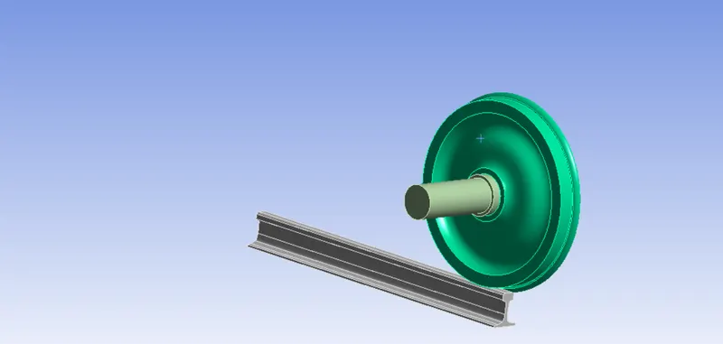
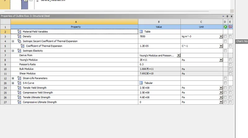
6. Assign the material to the model, as in our case we have structural steel, the material will asign automatically. If we need another material then we have to click on the model, which we have to assign the material. The below figure shows the material properties of a structural
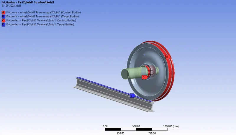
frictionless properties are defined
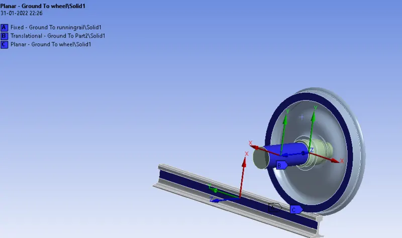
8. Insert a fixed joints for the track in order to act stable. So click on connections go to insert and select joint. select body to ground option, type as fixed and select the both face of the track for reference.
Insert a translational joints for the shaft in order to translate about the X-Axis. So click on connections go to insert and select joint. select body to ground option, type as translational and select the face of the shaft for reference.
Insert a Planar joints for the Wheel. So click on connections go to insert and select joint. select body to ground option, type as Planar and select the face of the Wheel for reference.
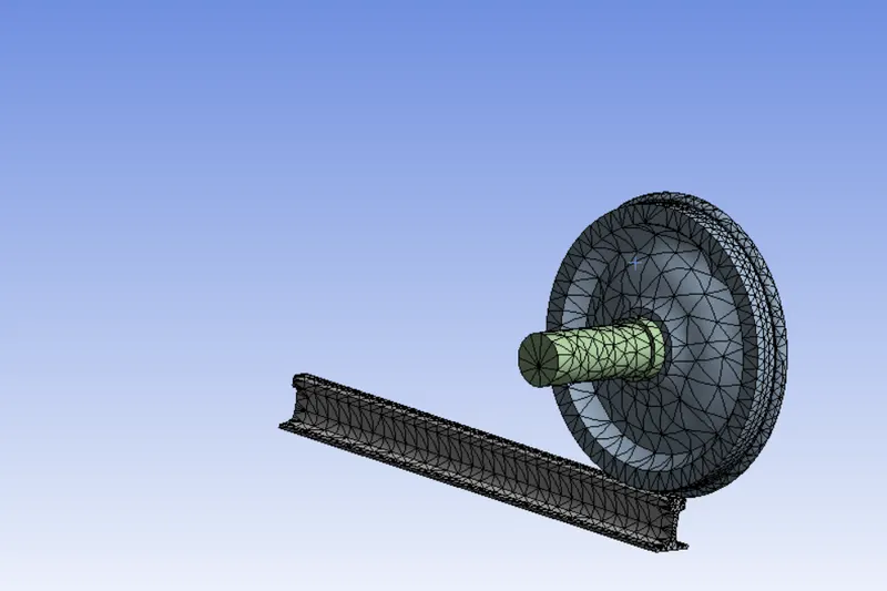
9. In ANSYS automatic mesh will be performed with Default mesh size and change the mesh size as 50mm. (ie Ansys student version will have a limted number of elements and nodes.)
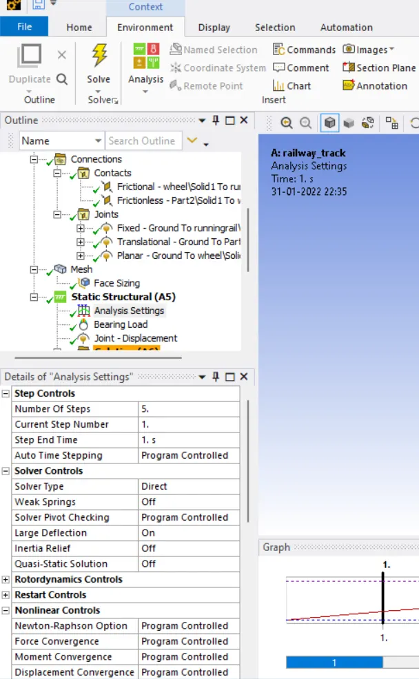
Analysis settings Change no. of steps as 5, auto time as program control, large deflection on, solver type as direct, in output control make all parameters as yes, in nonlinear control make force converge on. This is followed for first time step.
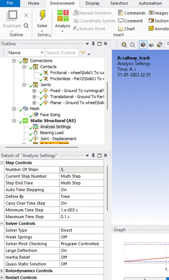
Analysis settings Change no. of steps as 6, auto time steeping on, define by time, carry over time step as on, minimum time step as le-3s, maximum time step as 0.1s. This is followed for time step second to fifth.
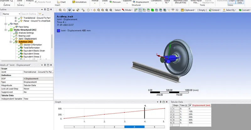
Now define the joint load for the shaft as translation joint. so click on the static structural and select joint load, change the type as displacement and with a magnitude of 0, 100, 200, 300, 400, 500
Now hide the shaft and select the inner surface of the hole and select the bearing load, define it by component and add the value y = -1e5.
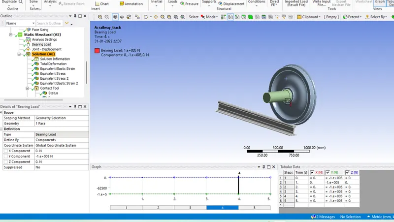
CASES:
Case 1: To Multiply the bearing load by 5 times and compare the results with the load of 100000 N. To Compare the Total Deformation, Equivalent stress and the life under both the loads
Case 2: To Implement a User defined result and To calculate the Total Deformation from this result and check if it is the same as that obtained by the inbuilt result by ANSYS for a load of 100000 N.
RESULT:
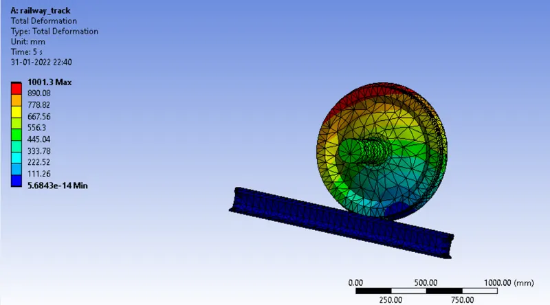
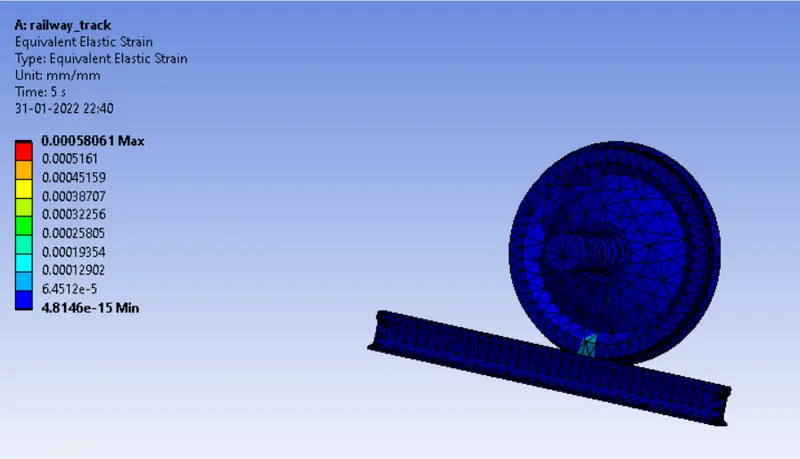
Simulation results for case-1 with different loads are as shown in below.
Case-1 with a Bearing load of 1000OON..
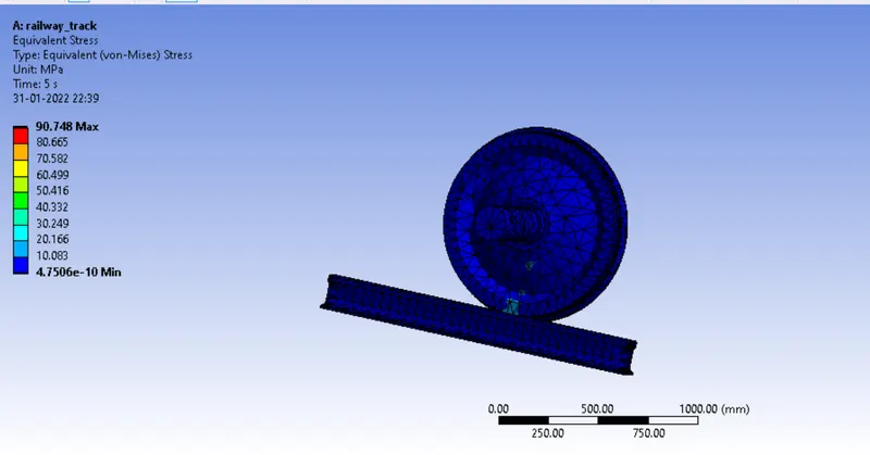
total deformation
strain
 .
.
BEARING LOAD OF 500KN
equivalent stress
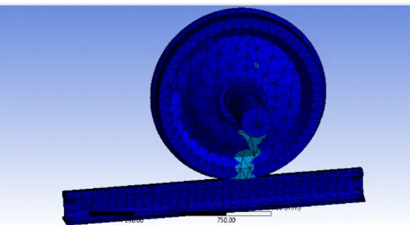
TOTAL DEFORMATION
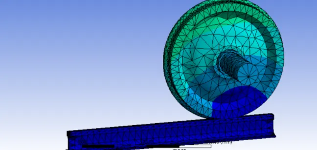
CONCLUSION:
From the table we can say that the stress is Maximum at 50000ON Load that is 673.16 and Minimum at 10000ON Load that is 188.53. The Fatigue will be minimum at higher load of 500000N which is 2532.3. And the Maximum fatigue remains same for both the cases. As well as the Total Deformation also remains same for both the cases.