Week 2 - Flow over a Cylinder.
ABSTRECT
Flow over a cylinder is a simulation to study the Karman vortex street flow which is generated. A Von Karman vortex street is a repeating pattern of swirling vortices arising in the wake of flows around cylindrical objects. In fluid dynamics, vortex shedding is an oscillating flow that takes place when a fluid such as air or water flows past a bluff body at certain velocities, depending on the size and shape. In this flow, vortices are created at the back of the body and detach randomly from either side of the body. The fluid flow past the object creates alternating low-pressure vortices or eddies on the downstream side of the object. The object will tend to move toward the low-pressure zone and flow separation occurs results in vortex generally found above Reynolds no. 40.
The computational fluid dynamics (CFD) package FLUENT as a fluid flow analysis tool to solve the governing equations, prominently equations of continuity, motion, and energy. Numerical results can be compared with experimental results and which was done by research scholar since due to model setup and lab constraints we will only compare the simulation results of different cases as per our objective. The mesh size is selected to do that the numerical solution is taken considering the computation time and simulation processing time. The flow has Reynolds no. above 40 shows Karman vortex street as per simulation results.
Keywords: Karman vortex street, numerical simulation, Fluent, CFD, laminar model, Reynolds No.
CONTENTS
Candidate’s undertaking i
Acknowledgment ii
Abstract iii
Contents iv
List of figures v
List of table’s vi
Nomenclature vii
Contents
CHAPTER 1: INTRODUCTION
-Introduction
-History
-Application
- What is a cylindrical body/object?
CHAPTER 2: LITERATURE REVIEW
- Introduction
- Review of Literatures
- Objectives
CHAPTER 3: METHODOLOGY
-Flow chart for CFD simulation
-Procedure/Steps for the CFD simulation
CHAPTER 4: RESULT AND DISCUSSIONS
CHAPTER 5: CONCLUSIONS AND FUTURE SCOPE
NOMENCLATURE
Symbols Significance
Re no. Reynolds No
d diameter of the cylinder
u free stream velocity
Cd. coff. of drag and
Cl. coff. of lift.
CHAPTER 1
INTRODUCTIO
Figure(1): shows the Karman vortex effect at Re. No. 100 at transient state
A Von Karman vortex street is repeating patterns of swirling vertices that are arising in the wake of flows around the blunt objects. The phenomena of vortex shedding are shown on flow over a two-dimensional cylinder in the above image. The fluid flow past the object creates alternating low-pressure vortices on the opposite side of the object and the object low-pressure zone is created.
Figure(2): Shows Streamline flow at the Karman vortex effect at Re. No. 100 flow over a 2D cylindrical surface.
Vortex shedding is an oscillating flow that takes place when a fluid flows past a body at certain velocities, depending on the shape and size of the body and other factors. In this flow, the vortices are created at the back of the body and detach randomly from either side of the body generating a Von Karman vortex street in a flow.
The bluff body is not fixed and the frequency of vortex shedding matches the natural resonance frequency of the object, then the object can begin to resonate and start vibrating. These vibrations can cause more damage to the object.
Figure(3): Shows Streamline flow at the Karman vortex effect flow over a 2D cylindrical surface and the velocity variation.[1]
Strouhal No:[2]
The Strouhal number is the ratio of inertial force due to the local acceleration of the flow to the inertial forces due to the convective acceleration. Inflows characterized by a periodic motion, the Strouhal number is associated with the oscillations of the flow due to the inertial forces relative to the changes in velocity due to the convective acceleration of the flow field. Thus, periodic flows are given by the following expression.
St= F *L/U
F= the frequency at vortex shedding (Hz )
L = characteristic length of the body(here Dia. of the cylinder)
U = Flow Velocity (m/s).
Consider a stream of fluid flow past a circular cylinder. As the fluid passes from the two extreme ends of the cylinder, it finds itself unable to negotiate the rear half of the cylinder where there is an uphill pressure gradient. Hence the fluid separates from the leading surface and the flow is separate individually with highly organized and typically consists of two sequences of vortices, one from each point of the body, with circulations of opposite signs. Depending on the shape and motion of the body more random patterns of vortices may arise. In the wake of the cylinder ie low-pressure area, the flow pattern consists of an alternating system of vortices or regions of rotation, as shown in Figure is '3'. This repeating pattern of swirling vortices at the wake of the cylinder is known as Karman vortex street.
It is important to note that even if the incoming flow is steady (i.e, does not change with time), the unsteadiness is intrinsically generated and the Karman street is formed downstream of the body. Thus causes turbulence due to variation in pressure an velocity.
A vortex street can be observed only. Beyond Re ≈40 the flow becomes unsteady and the Kármán vortex street occurs due to low-pressure gradient and low high velocity and fluid properties.
Figure(4): Shows flow vector during the Karman vortex effect at Re. No. 100; flow over a 2D cylindrical surface.
To check the vortex nature it is important to know the Reynolds no. The Reynolds number is a measure of the ratio of inertial to viscous forces in the flow of a fluid and may be defined as:
Reynolds No.[3]
Re = ρVD/ μ
where:
ρ = Density,
D = the diameter of the cylinder around which the fluid is flowing,
V = the steady velocity of the flow upstream of the cylinder and
μ = the kinematic viscosity of the fluid.
Figure(5): Flow variation at different conditions; flow over a 2D cylindrical surface.[4]
Drag And Lift:
Figure(6): Define the drag and lift direction on an aerofoil shape.[5]
It is a common experience that a body meets some resistance when it is forced to move through a fluid. You experience the same feeling when you extend your arm out of the window of a moving car. A fluid may exert forces and moments on a body in and about various directions. The force a flowing fluid exerts on a body in the flow direction is called drag.
A stationary fluid exerts only normal pressure forces on the surface of a body immersed in it. A moving fluid, however, also exerts tangential shear forces on the surface because of the
no-slip condition caused by viscous effects. Both of these forces, in general, have components in the direction of flow, and thus the drag force is due to the combined effects
of pressure and wall shear forces in the flow direction. The components of the pressure and wall shear forces in the direction normal to the flow tend to move the body in that direction, and their sum is called lift.
The drag and lift forces depend on the density 𝜌 of the fluid, the upstream velocity V, and the size, shape, and orientation of the body, among other things, and it is not practical to list these forces for a variety of situations. Instead, it is more convenient to work with appropriate dimensionless numbers that represent the drag and lift characteristics of the body. These numbers are the drag coefficient CD, and the lift coefficient CL, and they are defined as a formula
The drag and lift forces themselves are not as interesting as the dimensionless drag and lift
coefficients. These depend only on the Reynolds number and an object’s shape, not its
size. The coefficients are defined as
using the following parameters:
• FD and FL are the drag and lift forces
is the fluid’s density
• Umean is the mean velocity
• A is the projected area (product of thickness and diameter of a cylinder)[6]
History
Zdravkovich in an excellent monograph, has compiled almost all the experimental, analytical and numerical simulation data on flow past cylinders, available since 1938 and systematically classified this challenging flow phenomenon into five different flow regimes based on the Reynolds number. In the present study, the computation is restricted only to the first few regimes designated by Zdravkovich as (1) creeping laminar state (L1) of flow (0<Re<4)">(0<Re<4), (2) laminar flow (L2) with steady separation (4<Re<48">(4<Re<48) forming a symmetric contra-rotating pair of vortices in the near wake, (3) laminar flow (L3) with periodic vortex shedding (48<Re<180)">(48<Re<180) and finally (4) part of the transition-in-wake (TrW) regime (180<Re<400)">(180<Re<400) when the three-dimensional instabilities lead to the formation of streamwise vortex structure. Computations are carried out in the present work in the range of 0.1<Re<400">0.1<Re<400 for comparison with available measurement data or other computation results for both steady and unsteady flow situations. All the computations use an implicit pressure-based finite volume Navier–Stokes algorithm (RANS3D) for time-accurate prediction of the flow. This flow solution algorithm, originally proposed by the last author has been further developed at the CTFD Division, NAL, Bangalore during the last 10 years. The whole flow domain covering the L1–TrW regimes has first been computed under the assumption of two-dimensional flow. Later, in order to understand the effect of the three-dimensional disturbances on the complex wake vortex dynamics, three-dimensional analysis have been carried out at five different Reynolds number covering part of the L3 and TrW regimes, already reported in unclassified literature by a few researchers.
Table(1)TYPES OF FLOW OVER A CYLINDER AT DIFFERENT. REYNOLDS NO.
-Application
Strouhal made the first measurements of the frequencies associated with the shedding of vortices by defining a Strouhals number (S)
S = fD/L
where, diameter (D), speed (U), frequency (f)
Note: As Strouhal Number deals with frequency, it can be only obtained for transient type problems. Both Renolds number and Strouhals number are nondimensional numbers. On the practical side, the Karman street can lead to unwanted noise or even cause the failure of structures when the vortex shedding frequency coincides with the natural frequency of the structure. This type of vortex-induced oscillations can occur in a variety of situations such as chimneys, bridges, heat exchanger tubes, overhead power cables, and marine structures. Therefore understanding the physics of the Karman vortex street is crucial to avoid disasters in these situations.
It is important to reduce vortex-induced vibrations, drag, and lift force acting on them in order to prevent structural damage. Therefore, it is necessary to adapt control techniques in flow past circular cylinder to reduce structural damage and improve the service life of cylinder used for the particular application
- What is a cylindrical body/object?
A cylinder (or disk) of diameter 'D' is placed in a two-dimensional, incompressible, inviscid flow. The goal is to find the steady velocity and pressure p in a plane, subject to the condition that far from the cylinder.
Solutions:
The flow over a 2D cylinder is a very simple flow simulation and has a lot of fluid properties to be monitored while running it. While the flow can be witnessed in real life, It has a specific pattern that forms the Karman Vortex Street. its an oscillation flow phenomenon that can be observed very easily. So let's understand what the Karman Vortex street pattern is all about.
To describe in an informal way the flow created by the motion of a cylinder with constant speed in a fluid at rest. For very small Reynolds numbers, the flow is completely laminar around the cylinder, with no recirculation and no instability. For larger Reynolds numbers, a recirculation zone appears behind the obstacle. More precisely, two eddies with opposite signs appear just behind the cylinder and remain close to it. For larger Reynolds numbers, these eddies are unstable and successively leave the cylinder to propagate in the wake, to form the so-called “Von Karman” vortex street.
Above are some of the examples as to how the vortex pattern forms around a cylinder or any laminar flow at the obstacle in the center. We are going to perform the same phenomenon in ANSYS-FLUENT. First, we are going to create a geometry with a cylinder-like a shape in the middle which will have the same conditions as the cylinder at the center of any fluid flow path. We are going to create this in space claim.
The following are the tools we used to create the geometry and we have the same after the attempt of creation.
We used line tool to draw with dimensions
circle - 2m, with circle origin - -20 on X and +40 on X-axis.
box - 60x20m
and then used Pull to create a surface from the geometry that looks like
And then move on to Mesh.
Here we are going to perform mesh and to achieve a very fine Triangular mesh we have to perform certain steps to make sure it is desirable and
we are to be some different methods and tools to do so. Below are the steps involved in order to do so. This is the former mesh.
and that the next steps involve naming selection and making the mesh more fine around the cylinder as well as to the whole computational mesh.
the following are the tools involved:
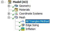
First, we try to add a method that let us convert quadrilateral mesh to triangle mesh
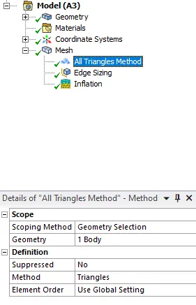
Though we are going to have undesirable physical simulation at the CFD post with this amount of MESH as we performed beforehand what elements size is suitable for that physical phenomenon.
So we further tuned it more to finer mesh with an element size of 0.25 and we have
further, for element sizing, we have a finer cylinder layer where we make it finer by increasing the number of edges by 36 having to be considered as 10 degrees between each other.
The same goes for the inflation layer.
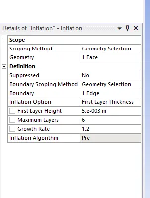
As you can see the layers are formed as we provided the layer quantity to the wall edge and that's how we get the finer edge mesh.
PART-I
- Simulate the flow with the steady and unsteady case and calculate the Strouhal Number for Re= 100.
Moving on to the Fluent we will simulate the above mesh with steady-state simulation and calculate the strouhal number. This part has 2 cases so first we run simulation for steady state. We will also animate the following output and to plot the contour we have:
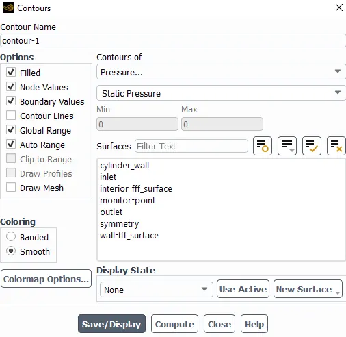
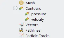
Thats how we got the contour of boh velocity and pressure here. The general information starts with pressure based solver with steady state and having Laminar Viscous model with usr defined material, which is air but we defined as custom material. This is how we find the suitable tools in fluent do perform these actions.
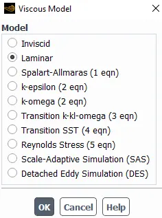
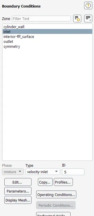
Here viscosity value is similar to as dynamic viscosity which is kinematic viscosity over density of the fluid. And then we ran for first 350 iteration with boundary condition below and then to 150 more to achieve up to 500 iterations.
OUTPUT:
case 1 : Steady state simulation of Reynolds number 100.
Plot of Vortex shredding behind the cylinder
DragCoefficient:
LiftCoefficient:
Strouhal Number: The Strouhal number is defined as St = fstD/U, where fst is the vortex shedding frequency (or the Strouhal frequency) of a body at rest, D is the diameter of the circular cylinder and U is the velocity of the ambient flow. And the relation between Strouhal number and coefficient of drag and lift is as follows:
Coefficient of Lift
Coefficient of drag
The contour of velocity magnitude :
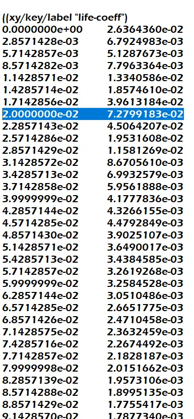
And when we open the FFT data file into an excel sheet we determined the magnitude of strouhal number as 2e-2 as the highest magnitude is
7.27e-2
Animation:
Case 2: Transient state simulation of reynolds number 100.
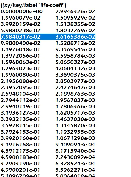
And when we open the FFT data file into an excel sheet we determined the magnitude of Strouhal number as 3.616e-2 as the highest magnitude is
7.98e-2
PART-II
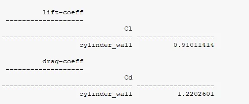
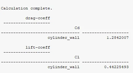
- Calculate the coefficient of drag and lift over a cylinder by setting the Reynolds number to 10,100,1000,10000 & 100000. (Run with steady solver)
- Discuss the effect of Reynolds number on the coefficient of drag. [ Results should be validated with any standard literature and error should be within 5 %]
Solution 1:
As we move forward for calculating the coefficient of drag and lift with Reynolds number. All the steps are the same as running the case in Fluent where we have to change the viscosity value in materials with different values and run the case.
Reynolds number : 10 100 1000 10000 100000
Viscosity : 0.2 0.02 0.002 0.0002 0.00002
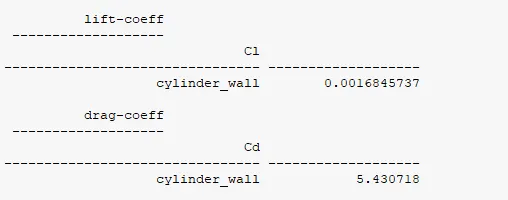
for Re = 10 and mu = 0.2
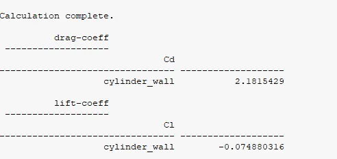
for Re = 100 and mu = 0.02
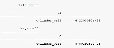
for Re = 1000 and mu = 0.002
for Re = 10000 and mu = 0.0002
for Re = 100000 and mu = 0.00002
Solution 2:
The effect of Reynolds number on the coefficient of drag and Lift done by aerodynamic experimentation of an airfoil with gurney flap
Lift coefficient decreases rapidly and drag coefficient increases rapidly when Reynolds number is decreased below critical range. This occurs due to a change in flow pattern near the Gurney flap at low Reynolds numbers.
A computational investigation on the effects of Reynolds number on the aerodynamics of NACA0012 airfoil without and with Gurney flap of the height of 3% airfoil chord has been carried out. ANSYS FLUENT commercial CFD code with one-equation Spalart-Allmaras turbulence model is used for the six Reynolds numbers varying from 3.0 × 10⁵ to 3.0 × 10⁴. From this investigation, the following major conclusions are drawn.
(1)Reynolds number plays a very major role in the airfoil aerodynamics for the NACA0012 airfoil without and with Gurney flap. Lift decreases and drag increases when Reynolds number is decreased.
(2)For the airfoil with GF, Reynolds number has adverse effects on lift coefficient, while the drag coefficient of the airfoil with GF has some beneficial effects compared to the airfoil without GF.
(3)For high Reynolds number above critical range, decrease in Cl and Cd increase in are negligible.
(4)As the Reynolds number is decreased below the critical Reynolds number range, Cl decreases and Cd increases at a very steep rate and the performance degrade rapidly.
(5)For lower Reynolds numbers, the two vortices behind the Gurney flap vanish. The Gurney flap seems to increase the effective camber of the airfoil, causing a negative zero-lift angle and reduced stall angle.
Conclusion of both cases:
And In both approaches, the flow has converged and we looked at a monitored control point plot to make sure that estimation. The frequent curve frequency shows that there's the presence of a physical phenomenon of vortex shedding around the cylinder wall.
Steady-state case
Unsteady state Case