Week 2 - Flow over a Cylinder.
Flow Over a Cylinder
Question: Simulate the flow over a cylinder and explain the phenomenon of Karman vortex street.
PART-I
Simulate the flow with the steady and unsteady case and calculate the Strouhal Number for Re= 100.
PART-II
Calculate the coefficient of drag and lift over a cylinder by setting the Reynolds number to 10,100,1000,10000 & 100000. (Run with steady solver)
Discuss the effect of Reynolds number on the coefficient of drag. [ Results should be validated with any standard literature and error should be within 5 %]
Theory:
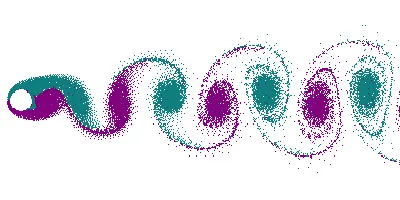
Vortex Shedding is the phenomenon that occurs when a fluid (air or water) flows past a blunt body (such as a cylinder) at certain velocities, depending on the size and shape of the body. In this oscillating flow, vortices are created at the back of the body and detach periodically from the sides of the body forming a “von Karman vortex street”. The fluid flow past the object creates alternating low-pressure vortices on the downstream end of the object. The object will tend to move toward the low-pressure zone. Furthermore, von Karman vortex street is a repetitive pattern of vortices, caused by a process called Vortex Shedding, which is responsible for the unsteady separation of flow of a fluid around blunt bodies.
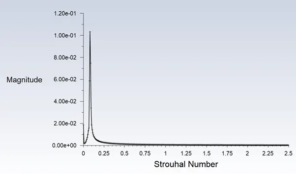
Strouhal Number is a dimensionless number used to describe oscillating flow mechanisms. The Strouhal number is given as:

where f is the frequency of vortex shedding, L is the characteristic length (for example, hydraulic diameter or the airfoil thickness) and U is the flow velocity.
Procedure:
- In Ansys Workbench, drag and drop Fluid Flow (Fluent) into Project Schematic.
- Open Spaceclaim to create the 2D drawing of the apparatus. An infinitely long cylinder of dia D = 2m is placed in an otherwise undisturbed uniform crossflow. The boundaries on either side are placed at a value of 10D and 20D from the center of the circular cylinder, respectively.
- In Spaceclaim, covert the above drawn figure into a surface by using “Pull” command. Delete all sketch lines and exit Spaceclaim when completed.
- Open Mesh generation module. Create Named Selections for Inlet, Outlet, the two long edges of the surface will be “symmetry” and Wall for the edge of the hole.
- Assign appropriate element size (0.225m in this report) as per grid-dependency test and generate triangular mesh. Ensure that the element metrics/quality is not lower than 5%. Edge sizing is given for the hole. (No. of edge divisions =36).
- 6 inflation layers at a distance of 0.005m from each other are assigned for better mesh quality around the hole. Exit Mesh module.
- Set the following data in Fluent Module for the simulation of Flow over a cylinder.
Part 1: Steady flow vs Unsteady Flow for Re = 100
|
Tab |
Criteria |
Parameter |
Value |
|
Domain |
Units |
Distance |
m |
|
Physics |
General |
Solver |
Pressure-Based |
|
Time |
Steady |
||
|
Velocity formulation |
Absolute |
||
|
2D Space |
Planar |
||
|
Models |
Viscous Model |
Laminar |
|
|
Materials |
Create/Edit Material |
Create New Material - "User Fluid" |
|
|
Zones |
Cell Zones |
Replace "Air" with "User Fluid" as simulation fluid |
|
|
Boundary Conditions |
Inlet Velocity = 1m/s |
||
|
Results |
Surface |
Create Point |
Create a "Monitor Point" at (8,0,0) from the centre of hole |
|
Graphics |
Contours |
Create Contour animations for pressure and velocity at "Monitor Point" |
|
|
Solution |
Solution |
Methods |
SIMPLE Scheme |
|
Reports |
Definitions |
New Surface Report-->Vertex Average |
|
|
New Force Report-->Lift |
|||
|
New Force Report-->Drag |
|||
|
Initialization |
Method |
Hybrid |
|
|
Initialize |
|||
|
Run Calculation |
No. of Iterations |
500 |
Note: The above set-up is done for Steady flow at Re=100. For unsteady flow the setup remains the same as above except for the following changes:
- Physics-->Time-->Transient
- Solutions-->time step size-->0.1
- Solutions-->No. of iterations-->750
Part 2: Calculate the coefficient of drag and lift over a cylinder by setting the Reynolds number to 10,100,1000,10000 & 100000. (Steady flow)
- Lift and Drag Coefficients are plotted as shown in the above table.
- Reynolds Number (Re) =
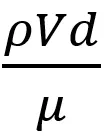
Where ρ = Density of fluid, V = velocity of fluid, d = diameter of cylinder and µ= Dynamic Viscosity
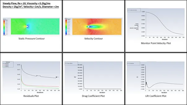
Case 1: Re = 10, Viscosity = 0.2 kg/ms, Density = 1 kg/m3, Velocity = 1 m/s, Diameter = 2 m
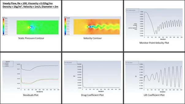
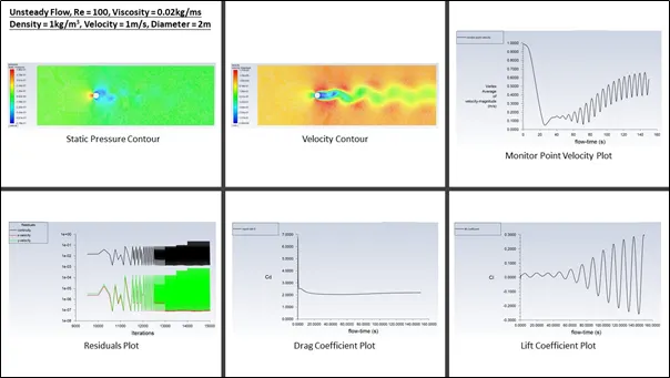
Case 2: Re = 100, Viscosity = 0.02 kg/ms, Density = 1 kg/m3, Velocity = 1 m/s, Diameter = 2 m
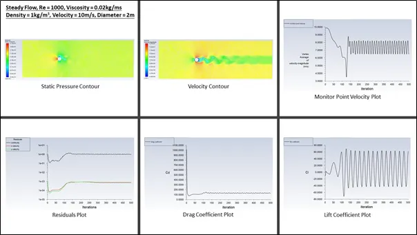
Case 3: Re = 1000, Viscosity = 0.02 kg/ms, Density = 1 kg/m3, Velocity = 10 m/s, Diameter = 2 m
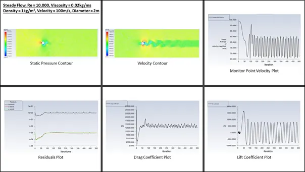
Case 4: Re = 1000, Viscosity = 0.02 kg/ms, Density = 1 kg/m3, Velocity = 100 m/s, Diameter = 2 m
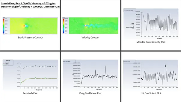
Case 5: Re = 1000, Viscosity = 0.02 kg/ms, Density = 1 kg/m3, Velocity = 1000 m/s, Diameter = 2 m
Results: The results are shown in the images below:
Conclusion:
- When Re increases Cd decreases.
- When Re > 4000, flow is turbulent and therefore laminar flow is small, leads to lower skin friction drag.
- When Velocity increases, Cd increases.
- When Re = 10, no vortices are seen as the velocity is low and only boundary layer separation occurs. The Cd, also increases.
- In Unsteady flow for Re = 100, the vortices can be seen and shedding frequency calculated.
- Strouhal number (For unsteady flow, Re = 100) can be seen below.
Measure to avoid Vortex Shedding:

To prevent Vortex Shedding and unwanted vibrations of tall cylindrical structures, a longitudinal fin can be fit on the downstream end, which, given it is longer than the diameter of cylinder, will prevent the formation of eddies. Helical projections are placed at the top of tall cylindrical structures, such as chimneys (as shown above). They are helical because wind can blow from any direction. Another measure to prevent vortex shedding in tall cylindrical structures is to vary its diameter with height, such as tapering. This prevents the entire structure being driven at the same frequency.