Flow over a Cylinder.
Introduction
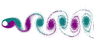
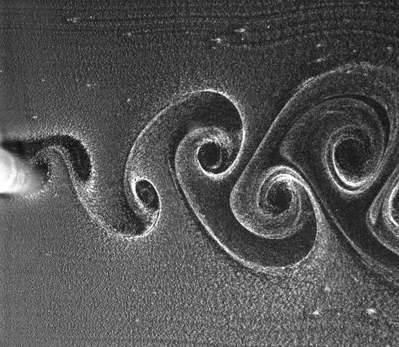
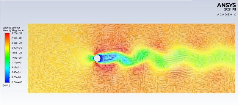
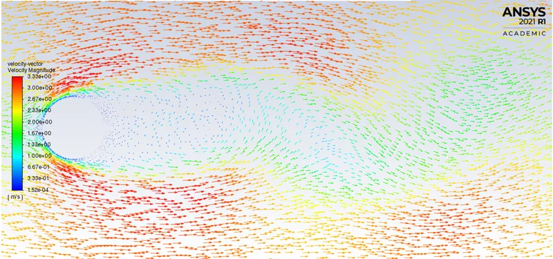
In fluid dynamics, vortex shedding is an oscillating flow that takes place when a fluid such as air or water flows past a bluff (as opposed to streamlined) body at certain velocities, depending on the size and shape of the body. In this flow, vortices are created at the back of the body and detach periodically from either side of the body forming a Von Karman Vortex Street. The fluid flow past the object creates alternating low-pressure vortices on the downstream side of the object. The object will tend to move toward the low-pressure zone.
If the bluff structure is not mounted rigidly and the frequency of vortex shedding matches the resonance frequency of the structure, then the structure can begin to resonate, vibrating with harmonic oscilations driven by the energy of the flow. This vibration is the cause for overhead power line wires humming in the wind, and for the fluttering of automobile whip radio antena at some speeds. Tall chimneys constructed of thin-walled steel tubes can be sufficiently flexible that, in air flow with a speed in the critical range, vortex shedding can drive the chimney into violent oscillations that can damage or destroy the chimney.
Reynold's Number
The transition from laminar to turbulent flow depends on the geometry, surface roughness, flow velocity, surface temperature, and type of fluid, among other things. After exhaustive experiments in the 1880s, Osborne Reynolds discovered that the flow regime depends mainly on the ratio of inertial forces to viscous forces in the fluid. This ratio is called the Reynolds number.
`Re= (ρVD)/μ`
`rho` = Desnisty of fluid kg/m^3
V = Velocity of fluid m/s
D = diameter of cylinder
`mu`=dynamic viscosity of fluid Pa.s
Strouhal Number
Strouhal number is a dimensionless number describing oscillating flow mechanisms.

f is the frequency of vortex shedding, L is the characteristic length.
The Strouhal Number can be important when analyzing unsteady, oscillating flow problems. The Strouhal Number represents a measure of the ratio of the inertial forces due to the unsteadiness of the flow or local acceleration to the inertial forces due to changes in velocity from one point to an other in the flow field.
Porcedure
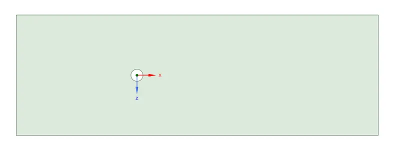
Create the gometry in SpceClaim and generating the surface using the pull tool
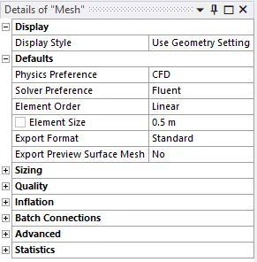
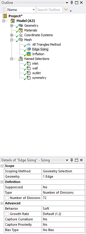
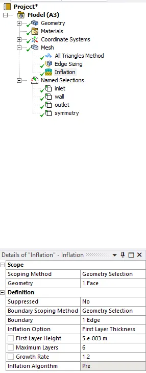
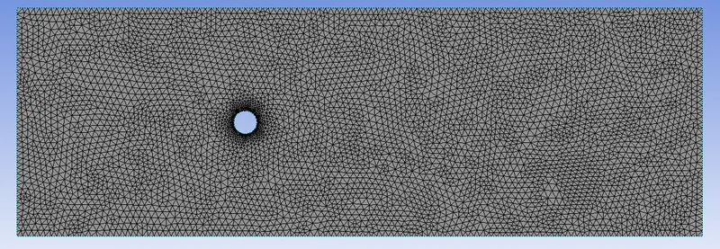
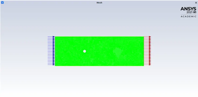
Meshing
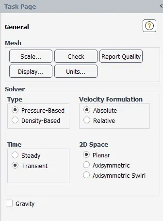
Setup
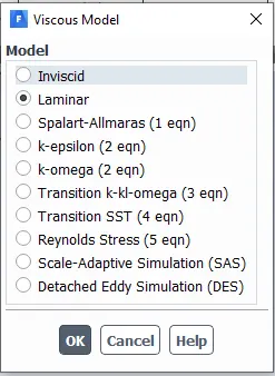
viscous model
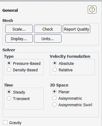
Steady state solver
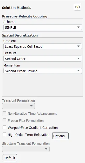
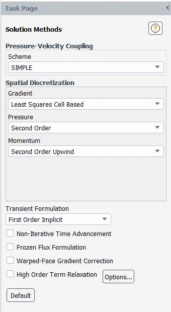
Solutin method
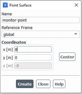
Monitor point
Transient simulation
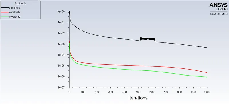
Case 1
Re = 10
velocity = 0.25m/s
viscosity = 0.05
No of iterations = 1000
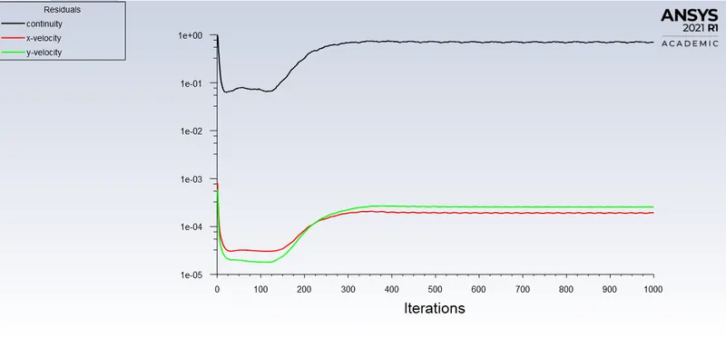
Residual plot
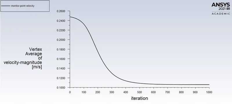
Monitor point velocity
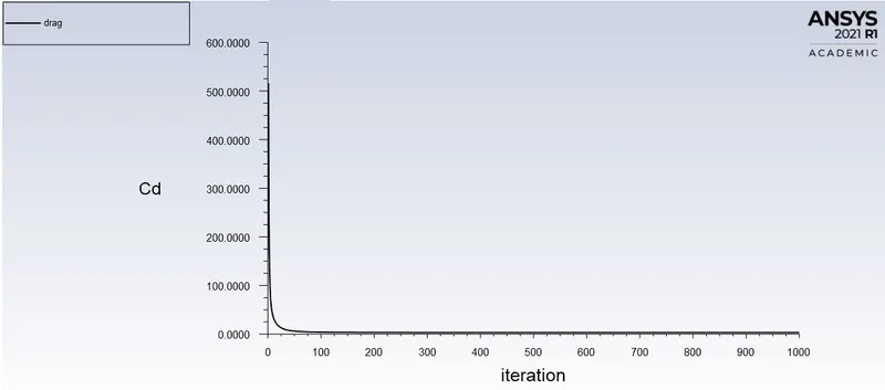
Drag Co-efficient
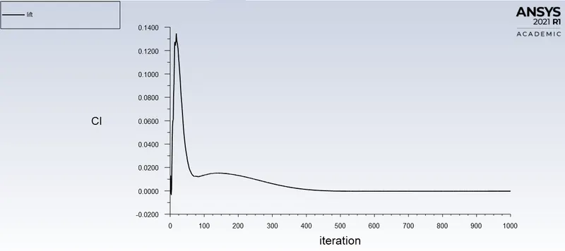
Lift Co-efficient
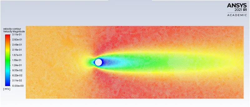
Velocity contour
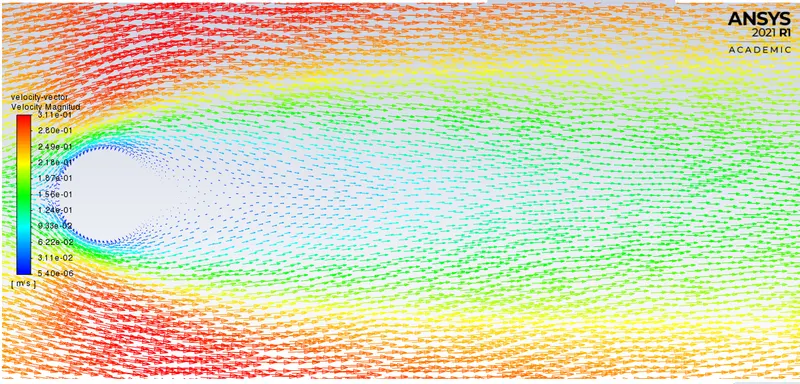
Velocity vector plot
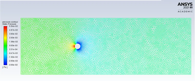
Pressure contour
Case 2
Re = 100
velocity = 2.5m/s
viscosity = 0.05
No of iterations = 1000
Residual plot
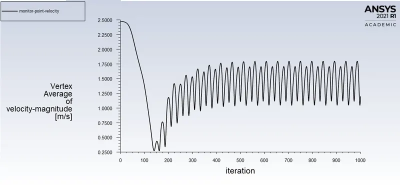
Monitor point velocity
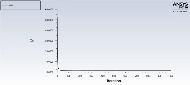
Drag Co-efficient
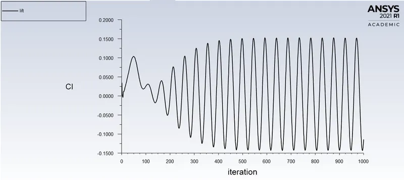
Lift Co-efficient
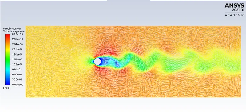
Velocity contour
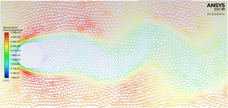
Velocity vector plot
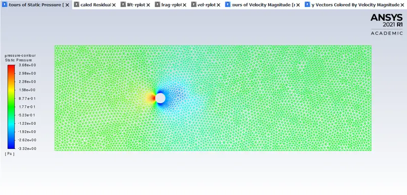
Pressure contour
Case 3
Re = 1000
velocity = 25m/s
viscosity = 0.05
No of iterations = 1000
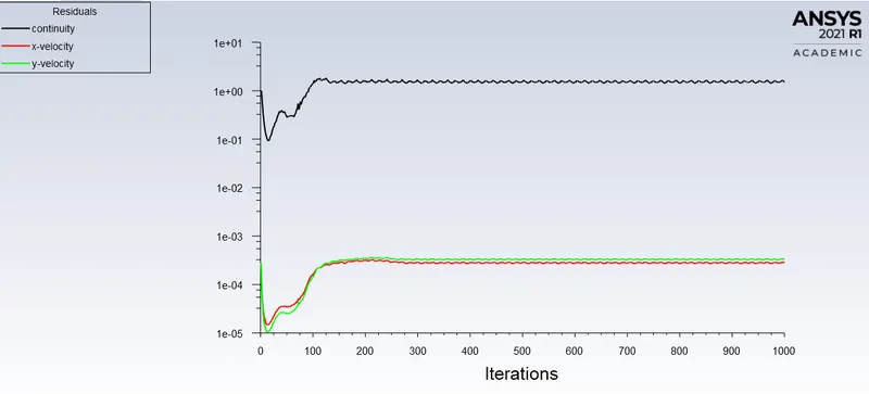
Residual plot
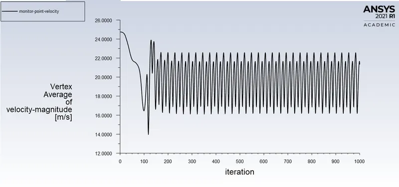
Monitor point velocity
Drag co-efficient
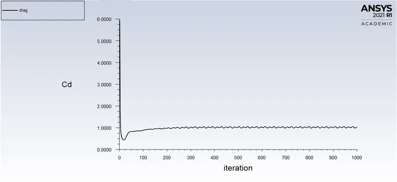
Lift Co-efficient
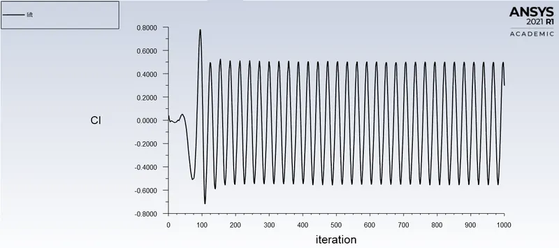
Velocity contour
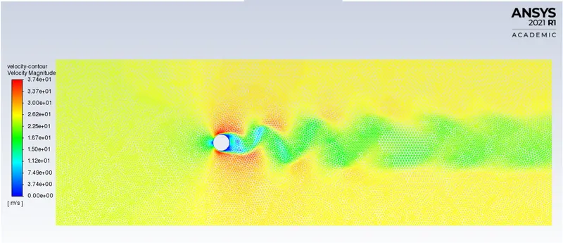
Velocity vector
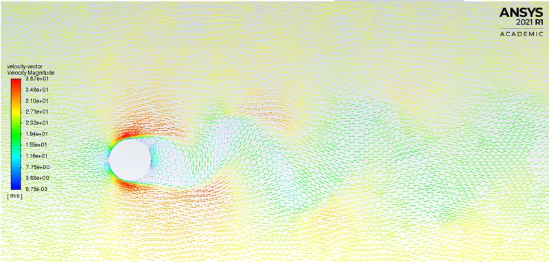
Pressure contour
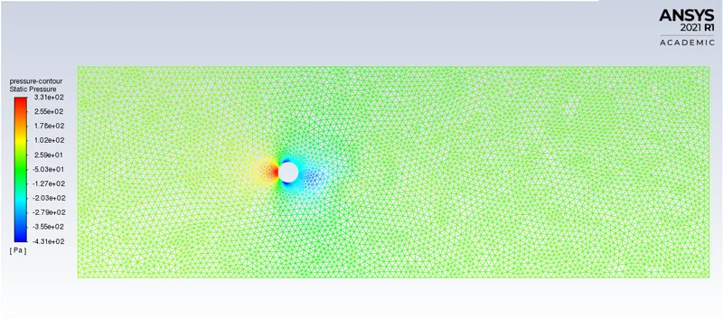
Case 4
Re = 10000
velocity = 250m/s
viscosity = 0.05
No of iterations = 1000
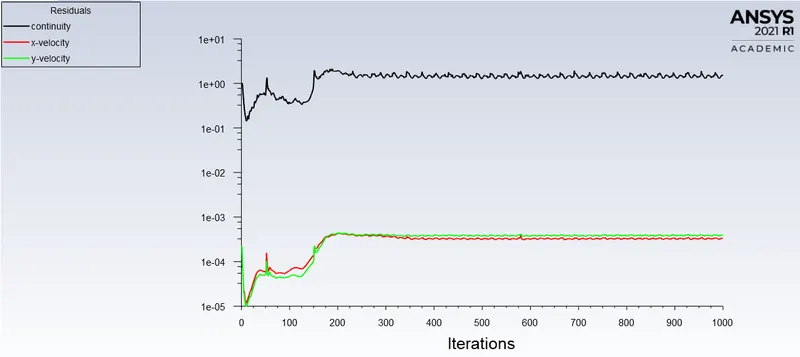
Residual plot
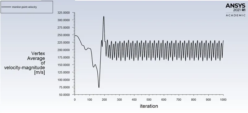
Monitor point velocity
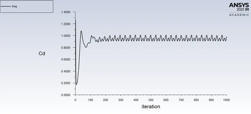
Drag Co-efficient
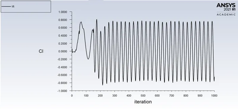
Lift Co-efficient
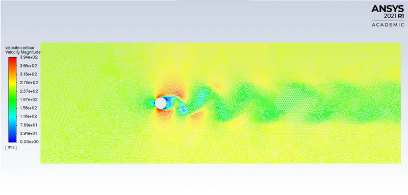
Velocity contour
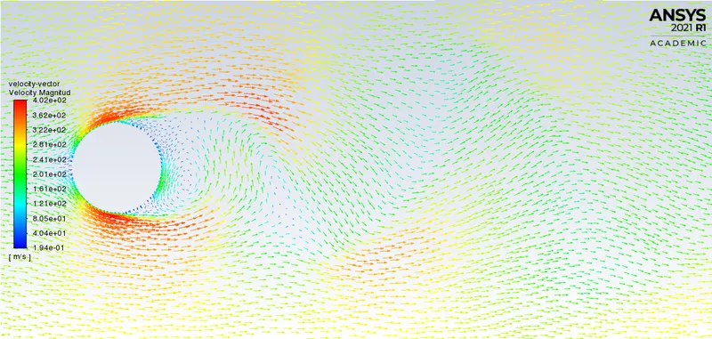
Velocity vector plot
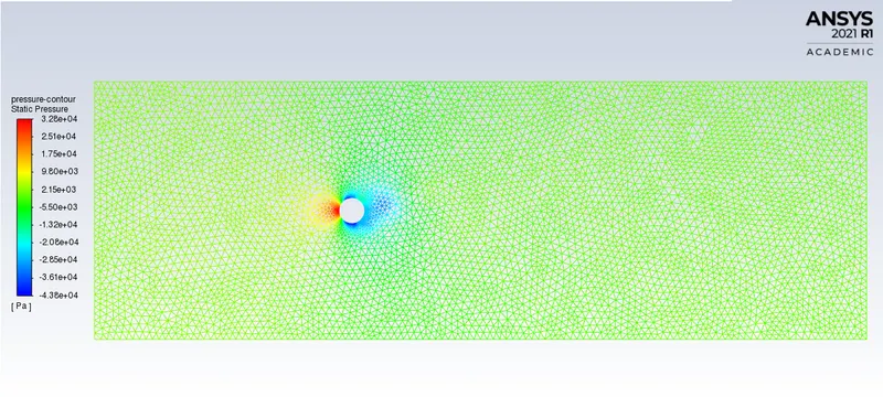
Pressure contour
Case 5
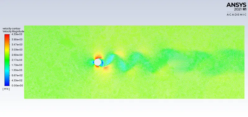
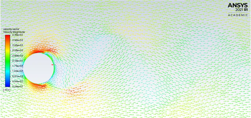
Re = 100000
velocity = 2500m/s
viscosity = 0.05
No of iterations = 1000
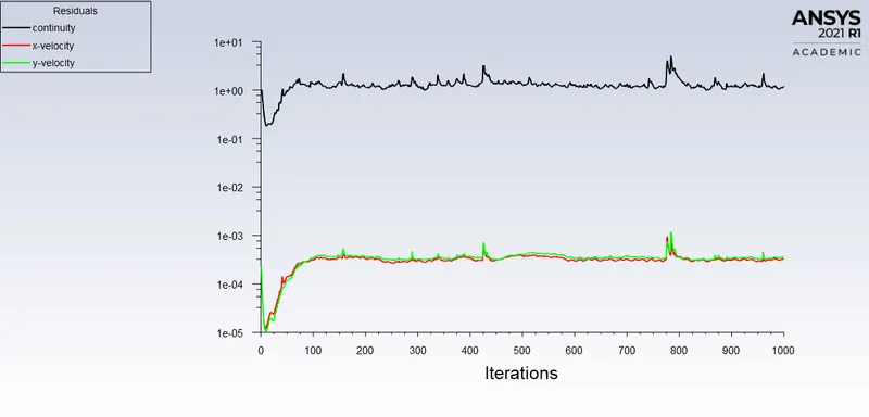
Residual plot
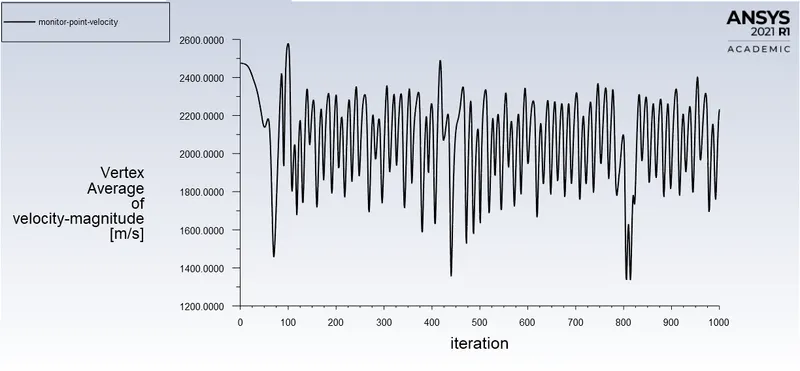
Monitor point velocity
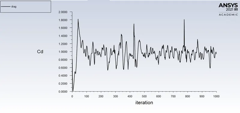
Drag Co-efficient
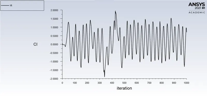
Lift Co-efficient
Velocity contour
Velocity vector plot
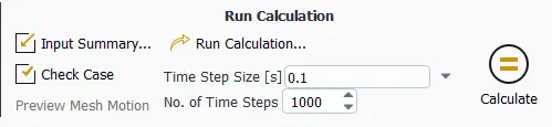
Transient simulation
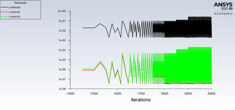
Re = 100
velocity = 2.5m/s
viscosity = 0.05
Time step size = 0.1
No of iterations = 1000
Residual plot
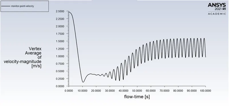
Monitor point velocity
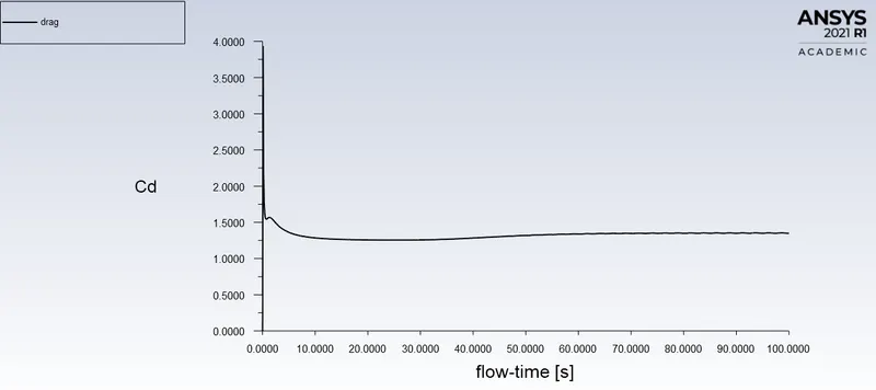
Drag Co-effiecient
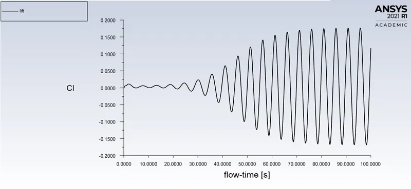
Lift Co-effecient
Velocity contour
Velocity vetor
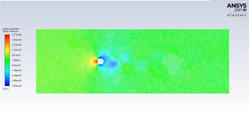
Pressure contour
Strouhal Number
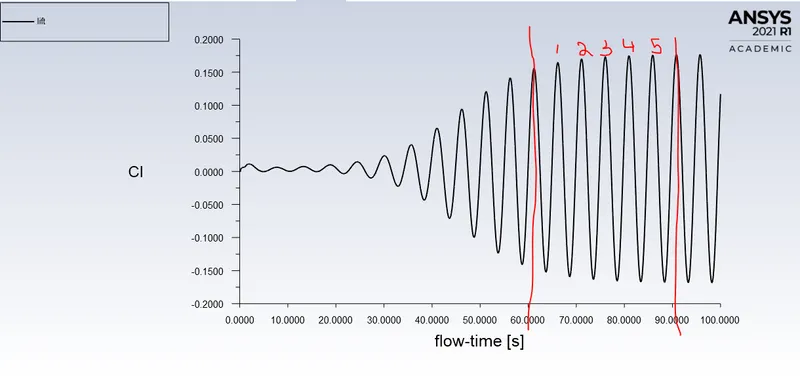
f = number of cycles/time = 5/30 = 0.16666
St = (0.16666*2)/2.5 = 0.133
Results:
|
Re number |
10 (Steady-state) |
100 (Steady-state) |
1000 (Steady-state) |
10000 (Steady-state) |
100000 (Steady-state) |
100 (Transient simulation) |
|
Velocity (m/s) |
0.25 |
2.5 |
25 |
250 |
2500 |
2.5 |
|
Drag Cd |
3.3333 |
1.3599 |
1.007 |
0.9833 |
0.9475 |
1.3500 |
When Reynold’s number increases, the coefficient of drag decreases as they are inversely proportional to each other. When the Reynold’s number is large (Re>4000), the flow will be turbulent (Chaotic and swirling vortices) in which laminar flow is very small, hence leads to lower skin friction drag.
In order to prevent the unwanted vibrations of cylindrical bodies, a longitudinal fin can be fitted on the downstream side, provided the fin is longer than the diameter of the cylinder, will prevent the eddies from interacting, and consequently remain attached. For example, for a tall building, the relative wind could come in any direction. For this reason, helical projection resembling larger screw threads are sometimes placed at the top of the building, thereby discouraging the shedding of vortices.
The counter measure for tall buildings is using variations in diameter with height, such as tapering- which prevents the entire building being driven at the same frequency. Foe ex, spiral added to the chimney need to avoid vortex shedding.