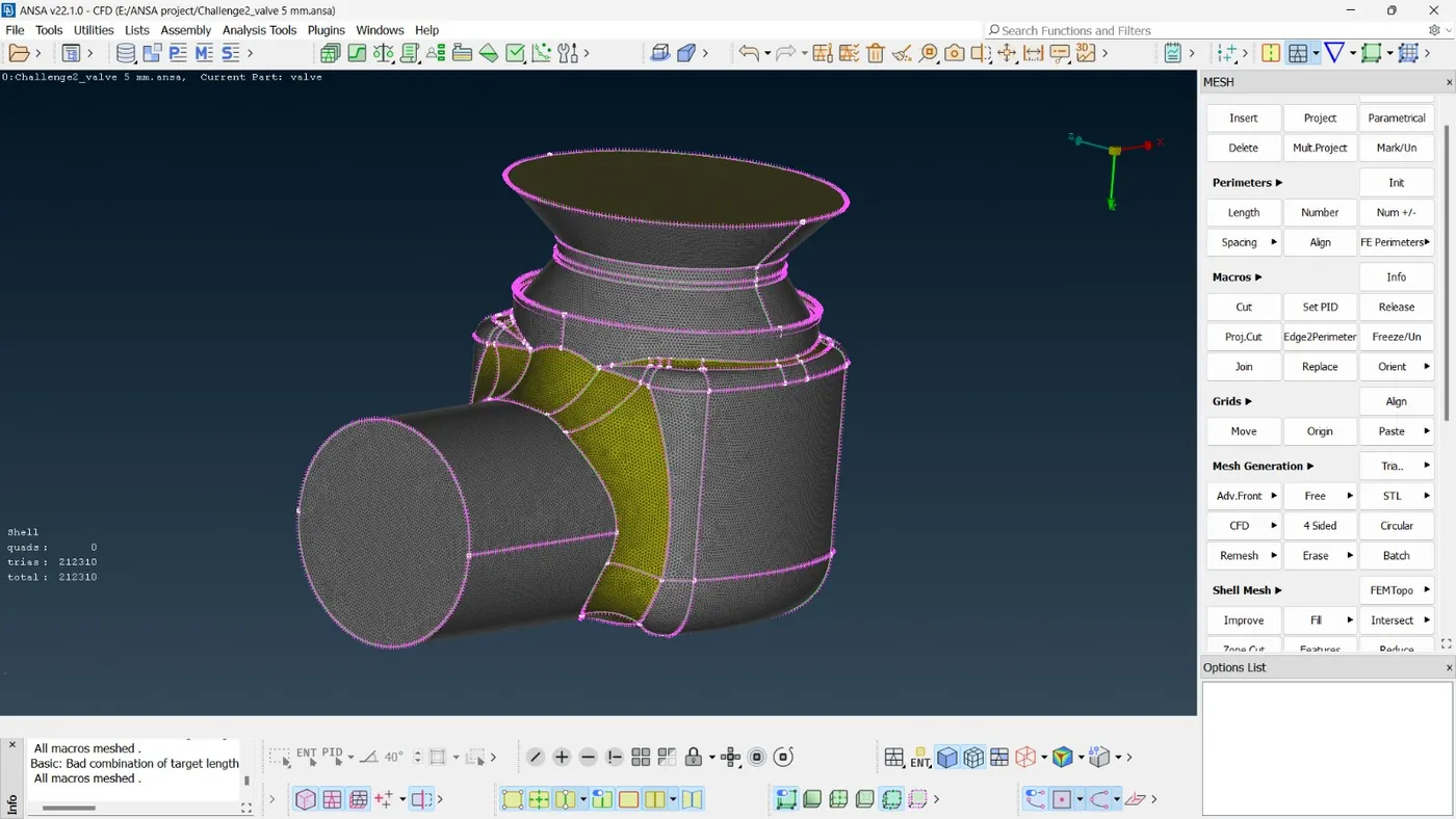
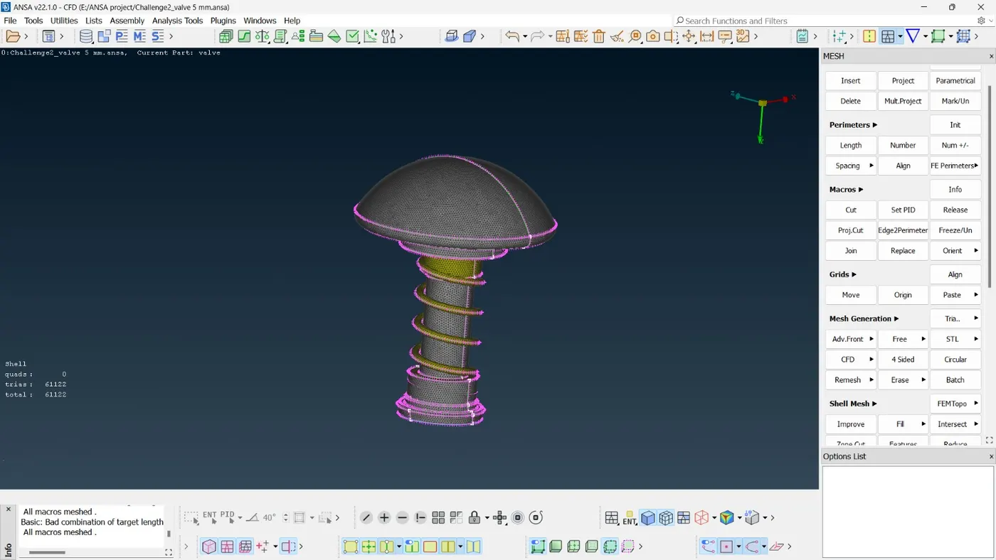
Week 2 Challenge : Surface meshing on a Pressure valve
Objective: This project aims to create a surface mesh on a Pressure Valve using ANSA pre-processing software. The basic operations involve geometry import with .ANSA extension, using the TOPO tool for checking geometry topology and geometry cleaning, setting up PID regions, setting up meshing parameters, and eventually generating the mesh of desired quality.
Procedure:
- The model was imported into ANSA GUI.
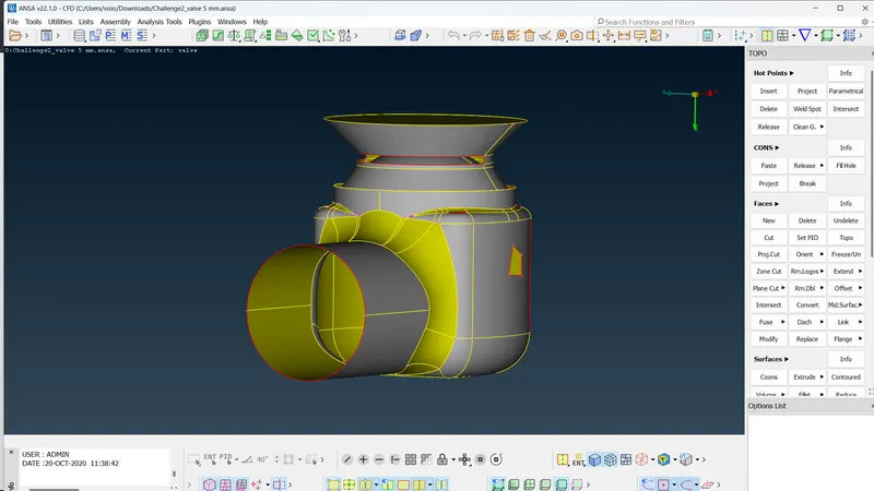
- Before proceeding to mesh, a geometry check is necessary to identify the defects that exist, if any, and remove those defects for further proceedings in order to have a hassle-free mesh generation without errors.
- To set up the geometry check, a set of parameters is first chosen in the tick boxes against the names of the respective checks that one wants to carry out.
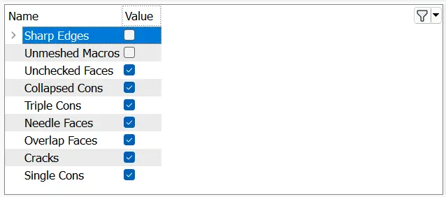
- After executing the error check run, we get to analyze the errors/defects that are present in the geometry and we can separately analyze each of the defects by clicking over any one.
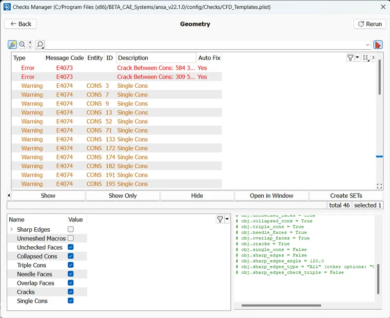
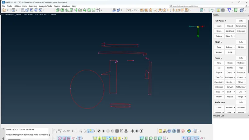
- For the sake of visual clarity, single cons can be viewed separately by hitting Ctrl+Shift or viewing in wireframe mode when only the single cons are enabled for display
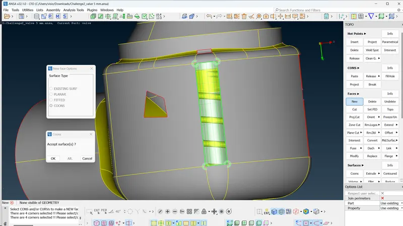
- Now, for the regions with defects, that is faces with one con only, new faces can be generated using existing faces or con loops. The New button in the Faces subsection can be chosen and using a loop for continuous cons selection, a new face can be generated using Coons option. For faces that need to be generated using existing faces, apart from selecting the cons, the required face needs to be selected too.
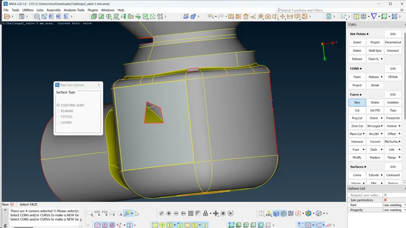
- The rest of the cracks and holes can be filled by directly using the Fill Hole command. It should be noted that the length of the opposite edges should be the same for the face creation to morph properly onto the edges. After correcting all the geometry defects, and topo operations, the geometry can be checked once more before proceeding.
Objective: This project aims to create a surface mesh on a Pressure Valve using ANSA pre-processing software. The basic operations involve geometry import with .ANSA extension, using the TOPO tool for checking geometry topology and geometry cleaning, setting up PID regions, setting up meshing parameters, and eventually generating the mesh of desired quality.
Procedure:
- The model was imported into ANSA GUI.
- Before proceeding to mesh, a geometry check is necessary to identify the defects that exist, if any, and remove those defects for further proceedings in order to have a hassle-free mesh generation without errors.
- To set up the geometry check, a set of parameters is first chosen in the tick boxes against the names of the respective checks that one wants to carry out.
- After executing the error check run, we get to analyze the errors/defects that are present in the geometry and we can separately analyze each of the defects by clicking over any one.
- For the sake of visual clarity, single cons can be viewed separately by hitting Ctrl+Shift or viewing in wireframe mode when only the single cons are enabled for display
- Now, for the regions with defects, that is faces with one con only, new faces can be generated using existing faces or con loops. The New button in the Faces subsection can be chosen and using a loop for continuous cons selection, a new face can be generated using Coons option. For faces that need to be generated using existing faces, apart from selecting the cons, the required face needs to be selected too.
- The rest of the cracks and holes can be filled by directly using the Fill Hole command. It should be noted that the length of the opposite edges should be the same for the face creation to morph properly onto the edges. After correcting all the geometry defects, and topo operations, the geometry can be checked once more before proceeding.
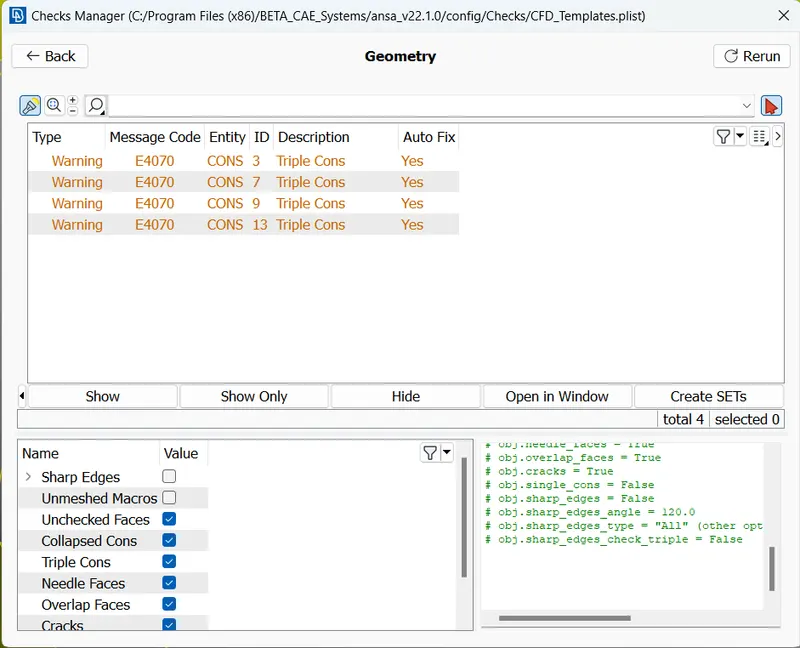
The only warnings visible are of triple cons, but they are not actual errors, so further proceedings can be undertaken.
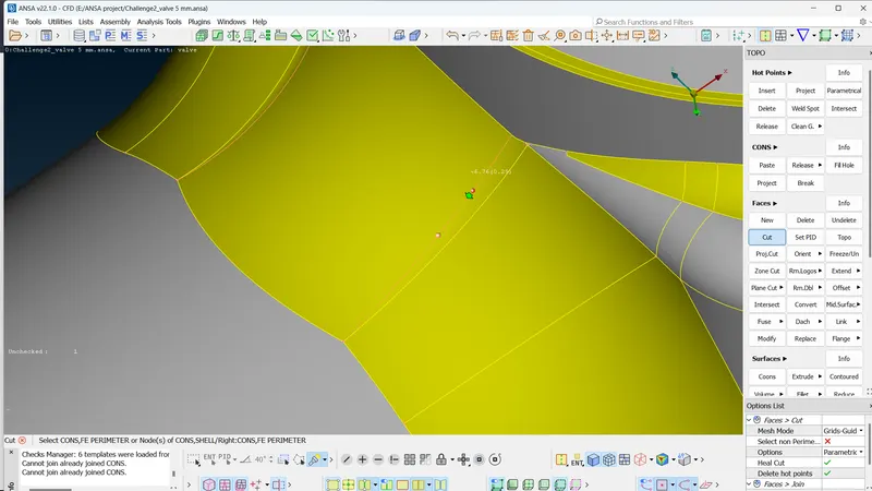
- The faces that have been created, in some regions, can be prohibitively too small for the size of the mesh element that one is meshing with so, they should be first removed using the Cut command in Face section.
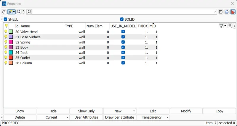
- The next process is assigning PIDs to different sections of the geometry that might serve the purpose of varying mesh lengths for different parts of the geometry. The set of PID regions that have been assigned in the current geometry are given in the below figure.
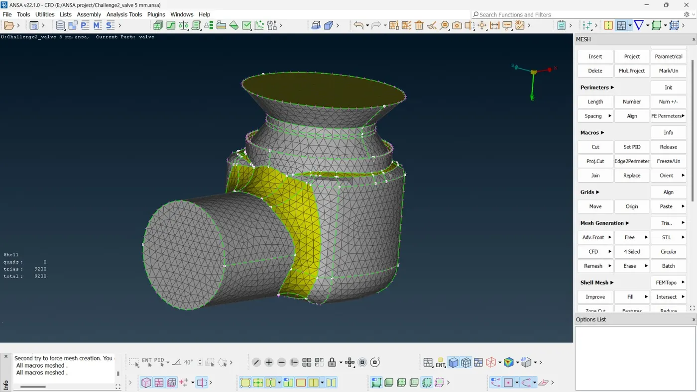
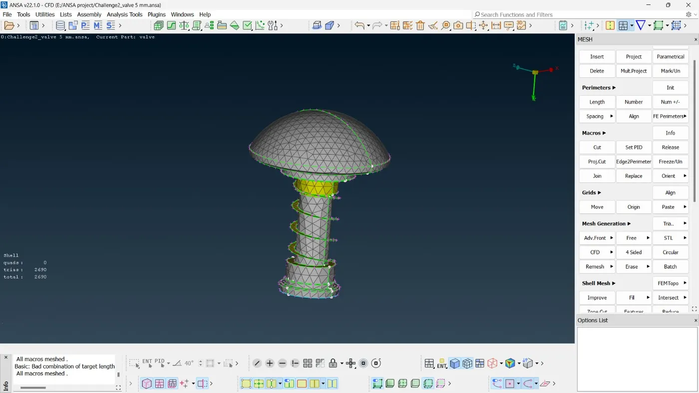
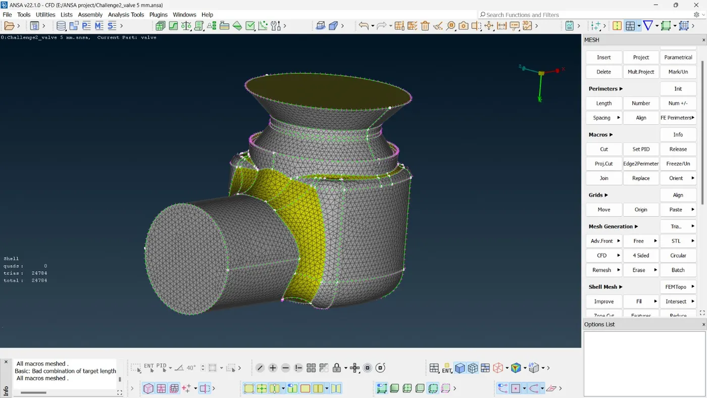
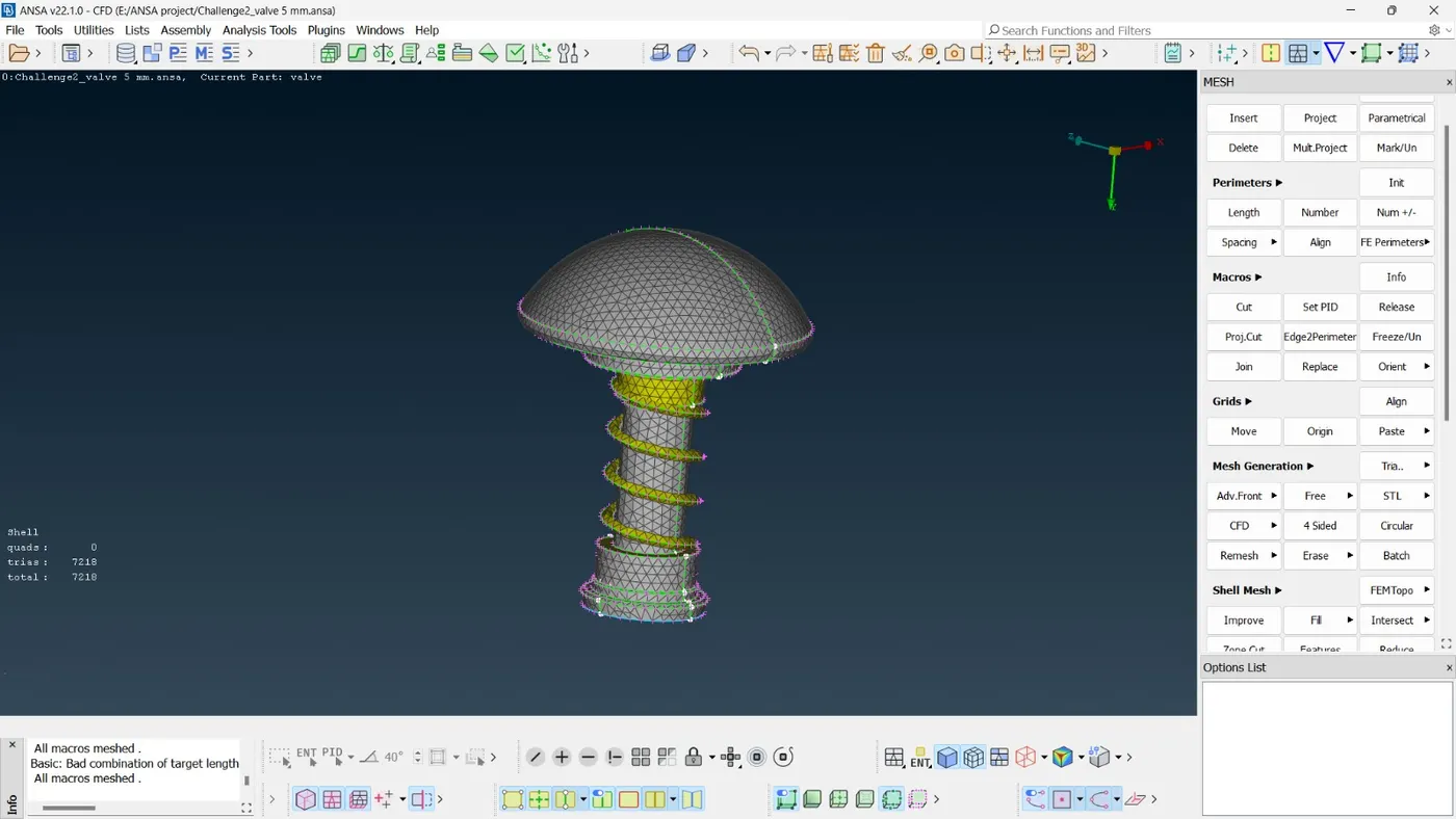
- In the final step, the mesh is generated using three different length parameters, that is, 1mm, 3mm, and 5mm. For meshing different PID regions, different PIDs are separately dealt with. If in the case that the sweep features or face size of certain PID regions happen to have dimensions smaller than that of the mesh length, then the mesh resolution can be made smaller enough to precisely capture the curvature of the shape.
- Case 1 (5mm) :
- Case 2 (3mm) :
- Case 3 (1mm) :