Week 2 Challenge : Surface meshing on a Pressure valve
Aim:
For the given model, check for the geometrical errors and perform Topology cleanup accordingly. Set three different target lengths as three different cases and mesh the model.
Objective :
Target length = 1mm, 3 mm and 5 mm (i.e. 3 cases)
Element type = Tria
Apply any one target length from the above at a time for the entire model as One case. Submit 3 different models for 3 cases.
Theory :
First of all lets see what is pressure control valve, so pressure control valve is used in system to prevent the damage caused by excessive pressure. These valve can do a pressure relief for system, an example for this is, using a line relief valve to limit the maximum allowable system pressure. These valves can be seen in hydraulic system to protect the system in order to achieve pressure control, pressure relief and pressure regulation must be done. The pressure is developed inn system because of restriction to flow fluid.
Why pressure control valve is used
- It can limit the maximum pressure
- Backpressure can be set
- These valves would send a signal if set pressure is reached
- It can protect the pump or system from over pressure
- It can unload a pump
- These valves set the pressure at which the fluid flows inside circuit
Procedure :
Geometry cleanup:
- First of all after opening geometry check the units, resolutions and orientation
- Next check the errors seen inn geometry or occurred in geometry
- To check the error click on check manager in which do full geometry check after checking we will get the list full of errors mentioning the errors present in geometry. We can see the geometry below in which the red lines shown are the single cons errors :
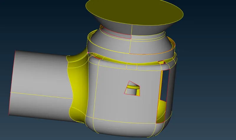
Fig 1: pre cleanup geometry
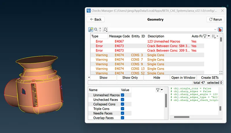
Fig 2: Errors in geometry
- As we check the errors now our next move is to overcome those errors. These errors are also visible on geometry in which nothing but some pieces of geometry are missing just like patches can be seen like if any single cons are visible then the parts there must be missing.
- Now we go to topo in which we select the faces as we have to add the patches there. In faces we have to select the type of surface we want where we have 4 options like existing surface, fitted, planer, and cons.
- So according to applications we select our type and clean the geometry. Now while doing this we also have to look on the geometry that any of the two lines shouldn’t come nearer to each other with distance less than mesh element size so if any then delete those lines by using cut lines option.
PID’s Creation:
- In this part we have to name the different parts with their specific colour which we can see below in images
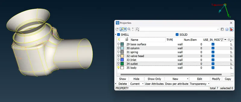
Fig 3: Body PID
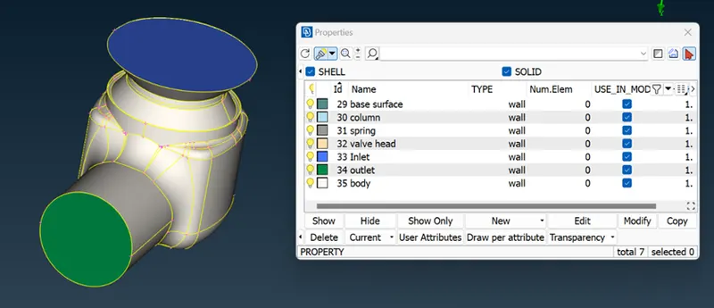
Fig 4: inlet and outlet
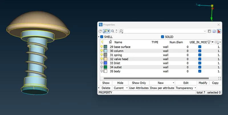
Fig 5: Valve inside PID
- Using PID we can create different mesh for different parts and also it is quite easy for us to find which part is where with its material id and different colour
Meshing:
- Now after completing all the geometry cleanup and PID defining lets start to our mesh. So we define the length first from perimeter and macros. for that first we select the perimeter/macros and then select the geometry which we have to mesh by box selection and then we hit the middle button to apply and then define the mesh length.
- Next we give same length in mesh parameter in front of target length (it may be 1, 3, 5mm according to our case)
- Then we go to mesh quality and define minimum length and maximum length du to which the mesh length shouldn’t exceeds the given length
- Again in mesh quality we define the type of mesh we want (tria, hexa, mixed)
- Next we goes to mesh generation and then select the spot mesh and then select the geometry we want to apply the mesh by clicking the middle button of mouse
- We can see the mesh created in images below with different target length :
We have three cases here
- 5mm target length
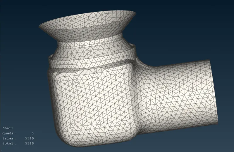
Fig 6:Body mesh with 5mm target length
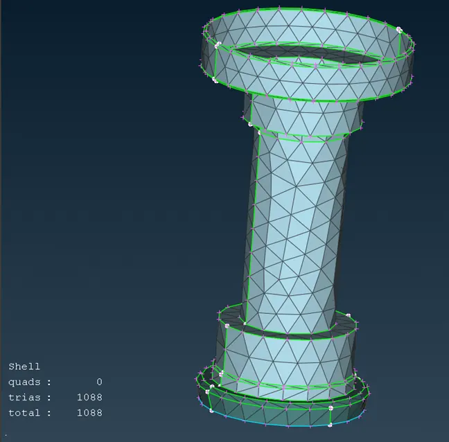
Fig 7:column mesh with 5mm target length
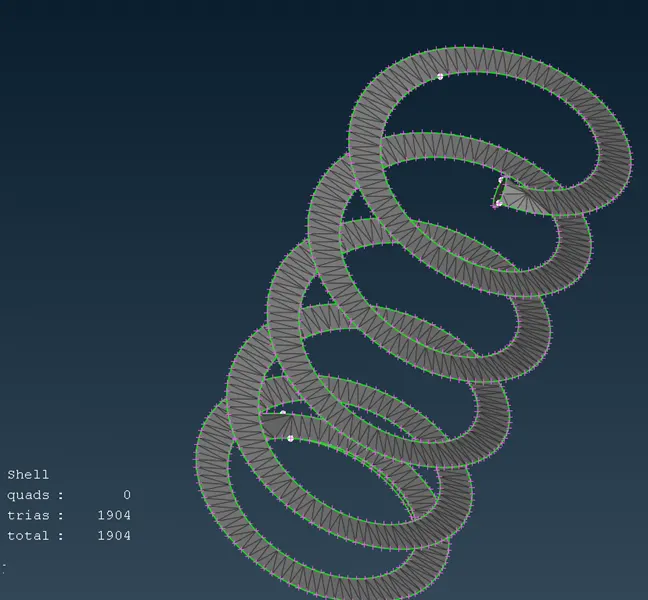
Fig 8:spring mesh with target length of 5mm
- 3mm target length
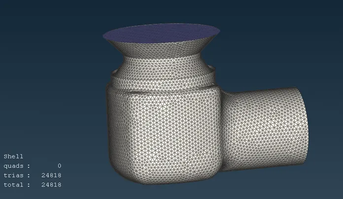
Fig 9:Body mesh with 3mm target length
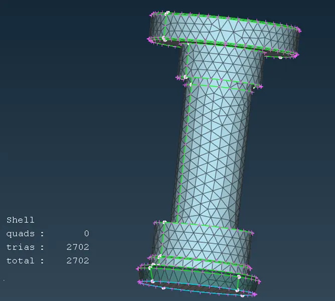
Fig 10:column mesh with 3mm target length
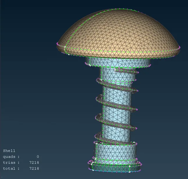
Fig 11: inner assembly at 3mm mesh target length
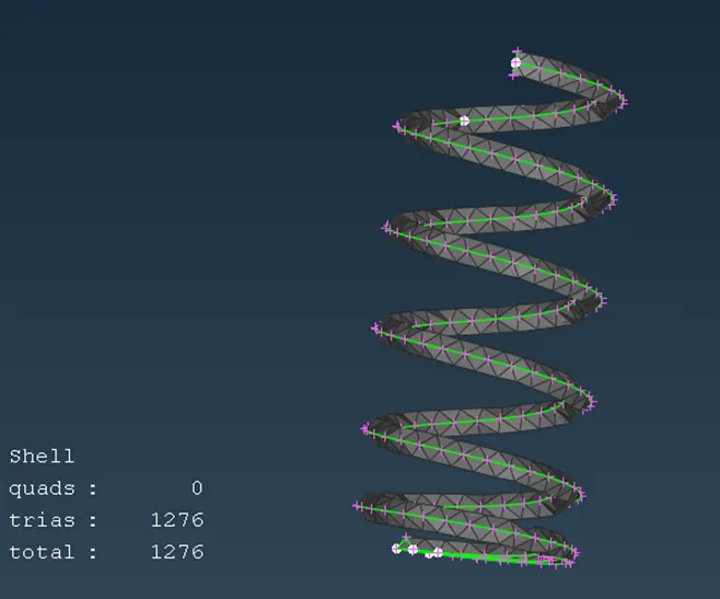
Fig 12:spring mesh with target length of 3mm
- 1mm target length
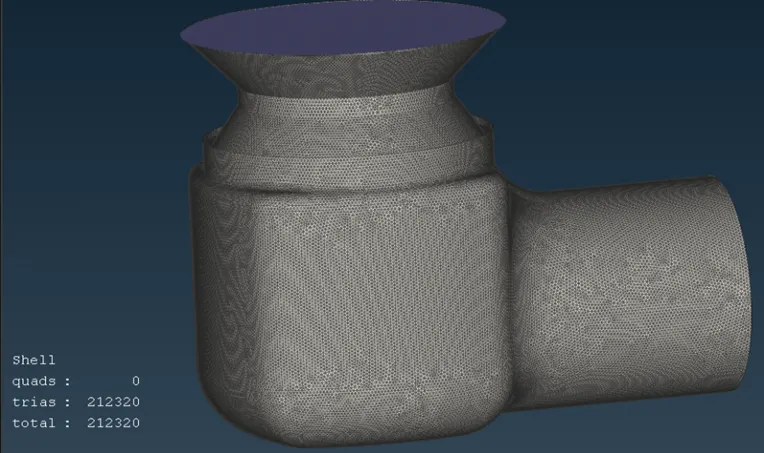
Fig 13:Body mesh with 1mm target length
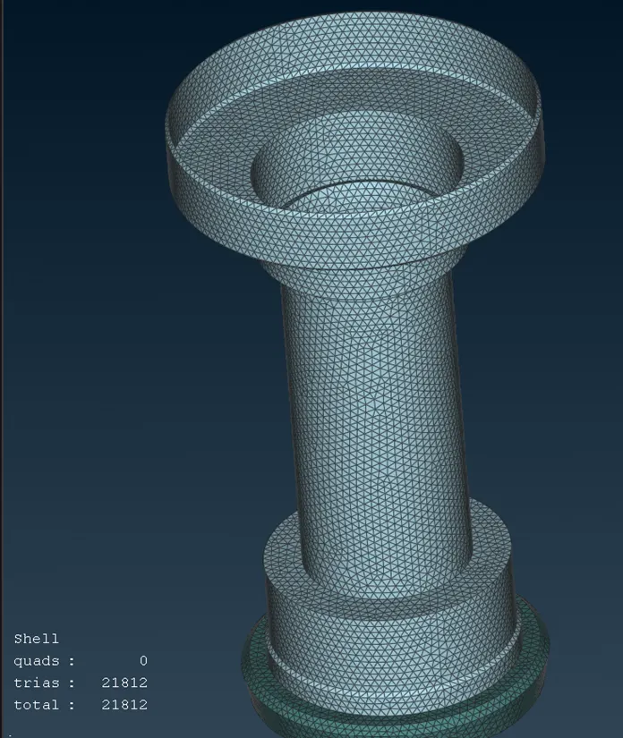
Fig 14:column mesh with 1mm target length
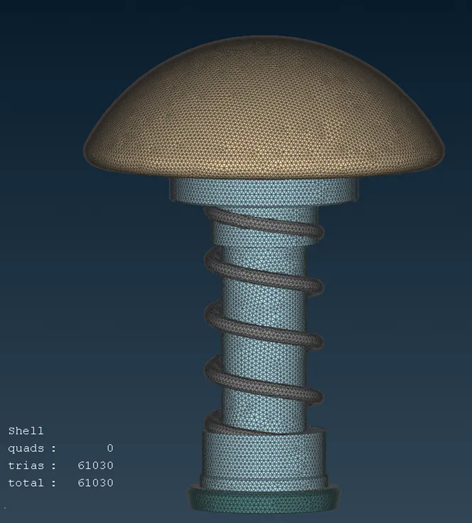
Fig 15: inner assembly at 1mm mesh target length
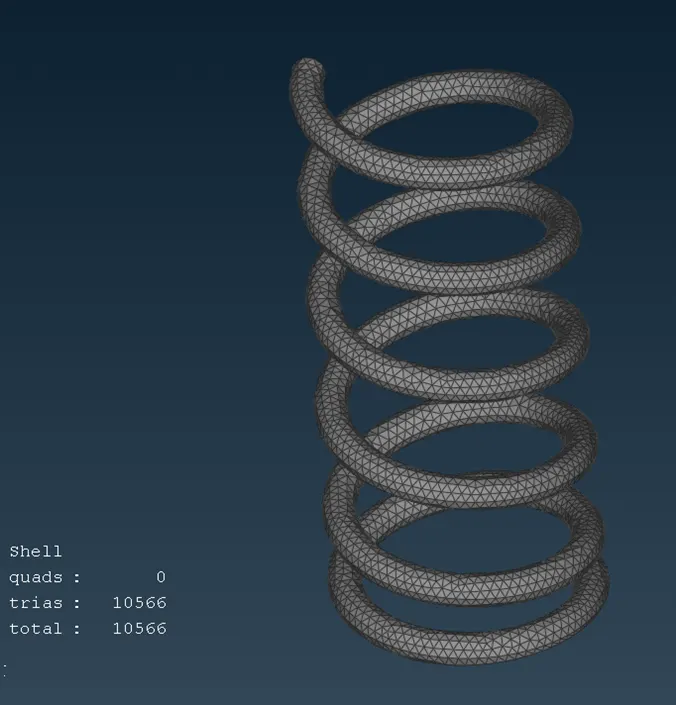
Fig 16: spring mesh with target length of 1mm
Learning Outcomes:
In this challenge after applying all these cases we can clearly see that as we decrease the mesh target length we get more defined geometry with higher accuracy and also increase in number of elements. So for more and higher accuracy we need our target length should be less.
Result :
|
Target length |
Components |
Number of elements |
|
5mm |
· Body · Column · Spring |
· 5546 · 1088 · 1904 |
|
3mm |
· Body · Column · Spring |
· 24818 · 2702 · 1276 |
|
1mm |
· Body · Column · Spring |
· 212320 · 21812 · 10566 |
Conclusion:
- In the end we conclude that defining the PID makes the work looks more easy and systematic way.
- Another points is as we decrease the mesh length we get more accurate result and more defining geometry and also increases the number of elements of mesh
- More the number of element more the computation power requires and more time it takes to simulate but to manage this we should use one technique in which we have to decrease the mesh length where we want to focus more like a particular part or the hotspot of geometry where we need more accurate results