Week 2 Challenge : Surface meshing on a Pressure valve
Aim: To mesh the valve model in 3 different mesh lengths and make a conclusive study
Procedure:
- We had to start by doing a topo cleanup. This was done by checking for any holes or single cons in the geometry surface.
- The checks could be done by Checks > Geometry > select the required parameters > Evaluate
- Once the single cons had been identified, new surfaces had to be created to fill in the gaps
- This was done by Faces > New > Selecting either of Fitted/Coons/Existing surfaces as per the use case
- Once the single cons were filled by selecting the cons via the Loop or Entity option, the holes in the outlet and bottom of the model had to be closed since CFD volumetric analysis cannot be done in an open model
- Then PIDs had to be created for each major entity in the model
- PID was created under the properties option and making new PIDs for each element, like Inlet, Outlet, Spring, Body, Valve head, etc
- Once the PID had been assigned using PID region option, we then check if there are any lines/entities that are small enough to create problems during meshing
- So we have to decide if the entities are smaller than what the mesh size will be. If they are, the lines in between must be deleted to create a bigger entity which can be meshed. So the whole geometry was checked for such anomalies and corrected
- Then we move onto meshing. Under the Mesh tab > Perimeters > Length > in both Macro and Perimeter the desired mesh length is given
- Then the mesh length and min and max length is defined in both Quality criteria and Mesh parameters. For 5mm length, min = 3, max = 7. For 1mm lenght, min = 0.5, max = 2. For 3mm length, min = 2, max = 5
- Under Mesh parameters, the element type is changed to tria is required.
- Under Mesh Generation > Spot mesh > Visible is selected to mesh the whole mode
Results:
We compare the smallest part, which is the spring, for 3 different mesh lengths to see which is the most suitable.
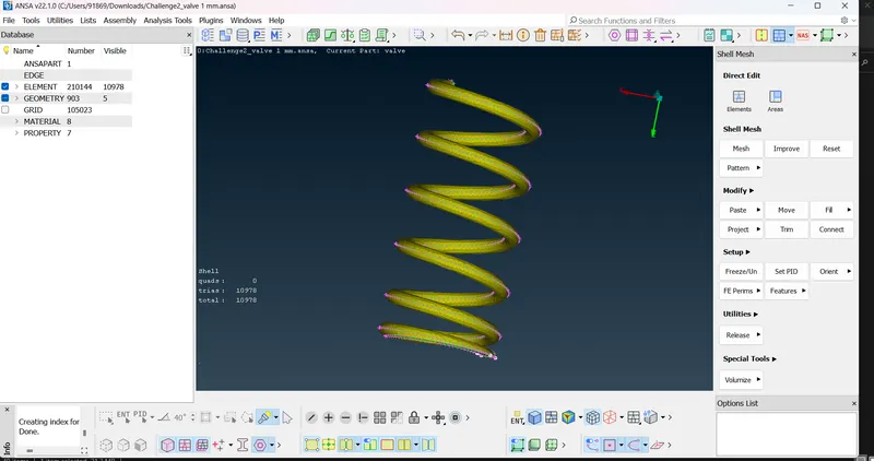
For 1mm mesh, we see that the mesh for the spring, which is the smallest part, is proper, and the number of elements is also highest, which will give an accurate result during analysis
Mesh length 3mm is shown below
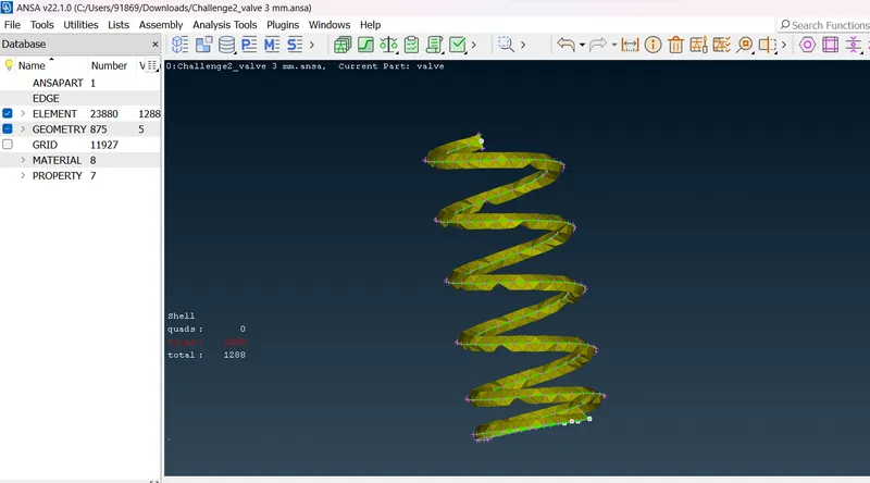
We see that the spring mesh is not proper, some elements are skewed and the number of elements has also decreased
Mesh size 5mm is shown below
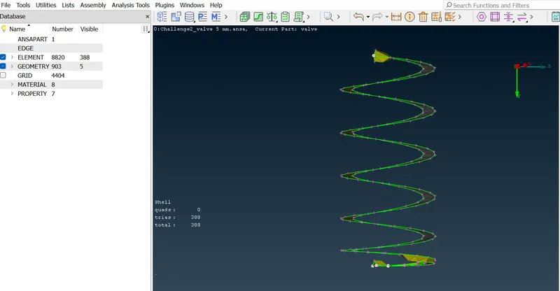
This has the worst mesh quality for the spring. This type of mesh will result in improper results during analysis
Conclusion:
From the results we conclude that 1mm mesh is the best to use since every element, especially the smaller ones are meshed properly and the number of elements is higher which results in more accurate outcomes.