Week 2 Challenge : Surface meshing on a Pressure valve
Aim/Objective: Surface Meshing on a Pressure valve with target lengths=1mm,3mm & 5mm, and the Element type is "Tria".
Procedure:
1st step is topology cleanup, in this step, one shall clean up the unwanted geometries in the model, like
- filling the holes,
- Adding faces on uneven surfaces,
- and getting rid of single cons, we can find the single cons by applying the Geometry check on the model
- and deleting the cons which are very close to each other for better meshing.
- The model must be closed from every side so that not a single con should'nt be present in the model.
After completing the topology cleanup we can further move into the PID creation part.
- With the properties tool's help, one can create many PIDs and assign different names as required, such as an outlet, inlet, body, valve head, spring, column, and the base surface.
- also, we can assign colours for each PID by double-clicking the colour option in properties and from the colour palette we can choose colours for PIDs.
- If there is an unwanted PID remains in properties we can remove it by adding a undelete method to remove that unwanted PID from the properties.
Meshing Procedure,
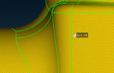
Following with the steps, Topological Cleanup, and PID creation, we can move to the meshing part of the model. Click on the classic mesh option and then start with the meshing process, first we have to follow the steps that are providing the length by selecting the model and setting the lengths for both perimeter and macros. giving target length in the mesh parameters and selecting the element type as Tria, and then giving the max and min length in the quality criteria.
then select the spot mesh and select the required region on the model and middle click for the final result for completing the meshing process.
Learning Outcomes:
- learned to check the geometry of the model,
- Topological cleanup,
- PID creation of different parts of the model individually,
- rectifying errors caused due to unwanted pids in properties,
- meshing with various target lengths.
- smaller element length size improves the geometrical sharpness, if the element size is the larger geometrical shape of the part can be compromised, we use a smaller target length for a better geometric shape
Result:
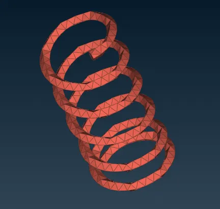
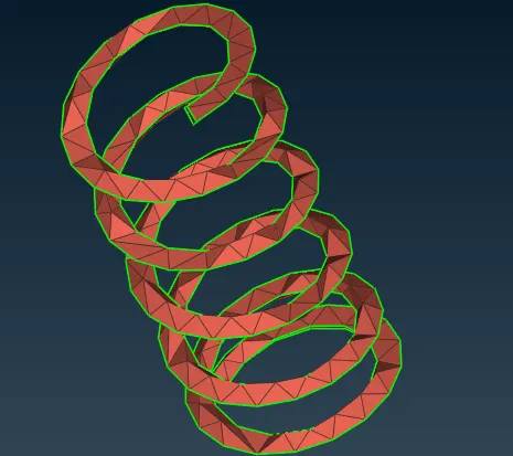
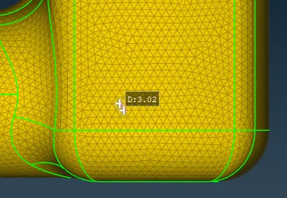
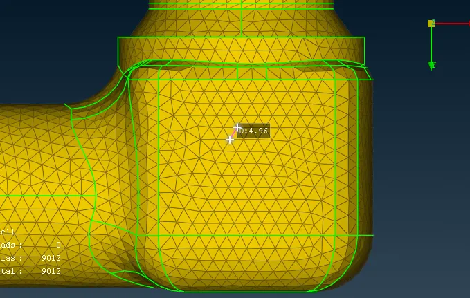
Surface Meshing of the model has been done with element type Tria with target lengths 1mm, 3mm & 5mm
Conclusion:
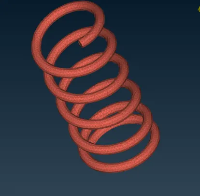
As shown in the below images we can conclude that If we decrease the target length which is less than that of part dimension as in this case diameter of the spring is 3 mm so to get true shape of the part after meshing the part we have to reduce the target length less than 3 mm or 1 mm.