Week 2 Challenge : Surface meshing on a Pressure valve
Aim:
For the given model, check for the geometrical errors and perform Topology cleanup accordingly. Set three different target lengths as three different cases and mesh the model.
- Target length = 1mm, 3 mm and 5 mm (i.e. 3 cases)
- Element type = Tria
Procedure:
Given geometry
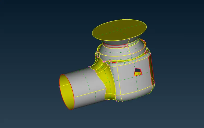
Geometry check:
Tools>checks>geometry
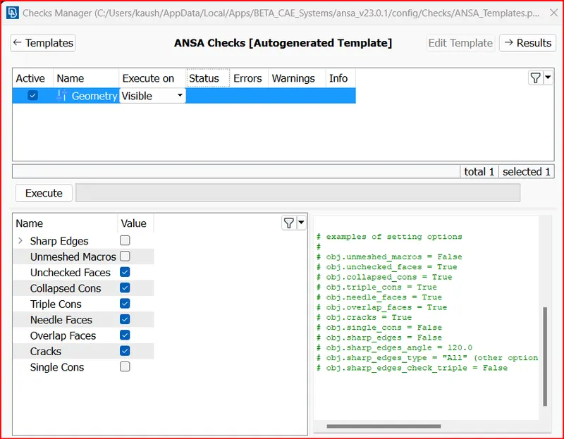
Errors detected in the preliminary check.
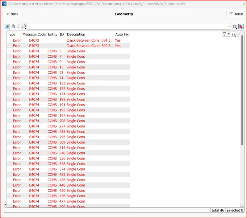
Geometry cleanup:
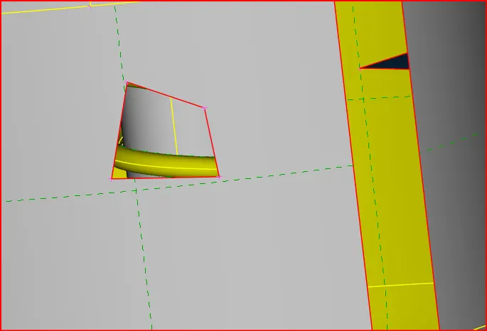
To fill the above surface>In Faces click on New>Existing surface>Select the cons>select face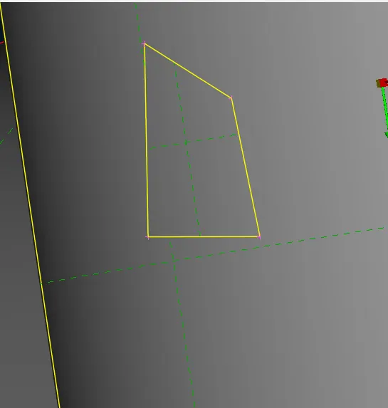
Fixed second surface using cooons and loop option.
close the outlet using Fill Hole command in the cons section.
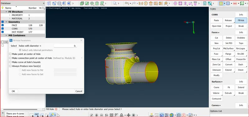
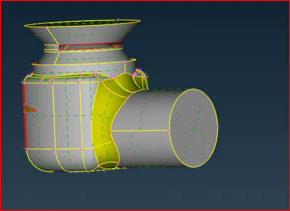
Created a nice clean geometry free of all single cons
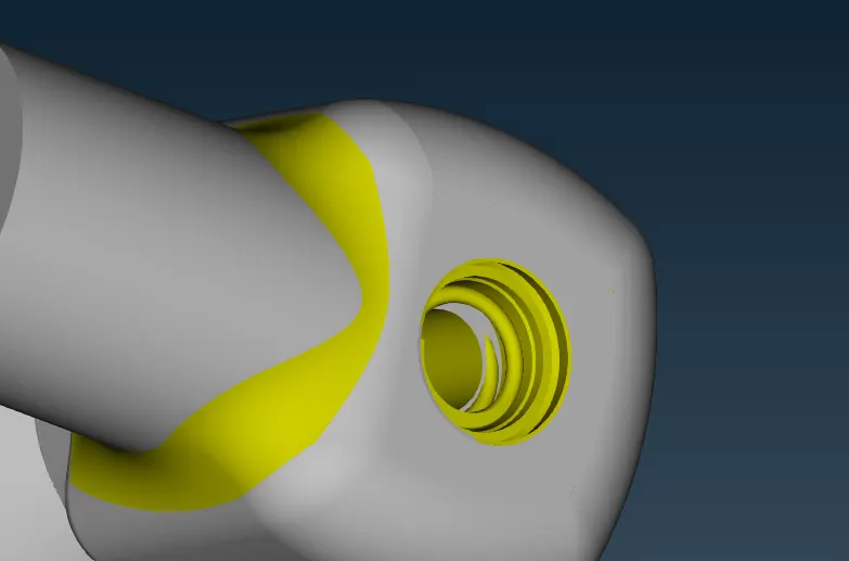 .
.
Now we perform the geometry checks
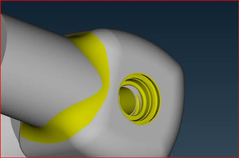
For cfd processing our model should be closed but the given model is open in the bottom hence we need to patch the surface.
Coons>select the double con>middle click.
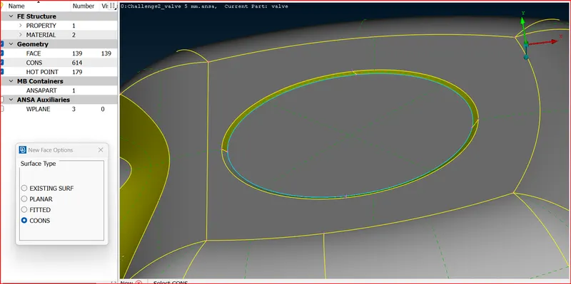
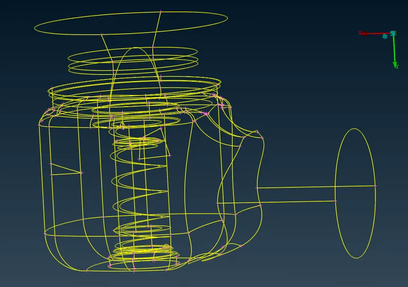
Wire frame appearance:
Double cons:
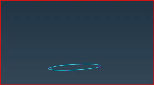
Triple Cons:
While designing any component a lot of small surfaces might be created in order to capture the features and maintain the shape.
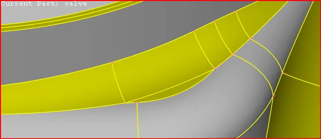
So the basic thumb rule is that the size of any surface must not be smaller than the largest mesh element size else that would interfere with the mesh.
So to do this go to cut right click on the edge.
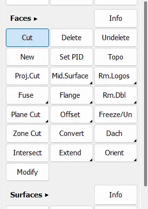
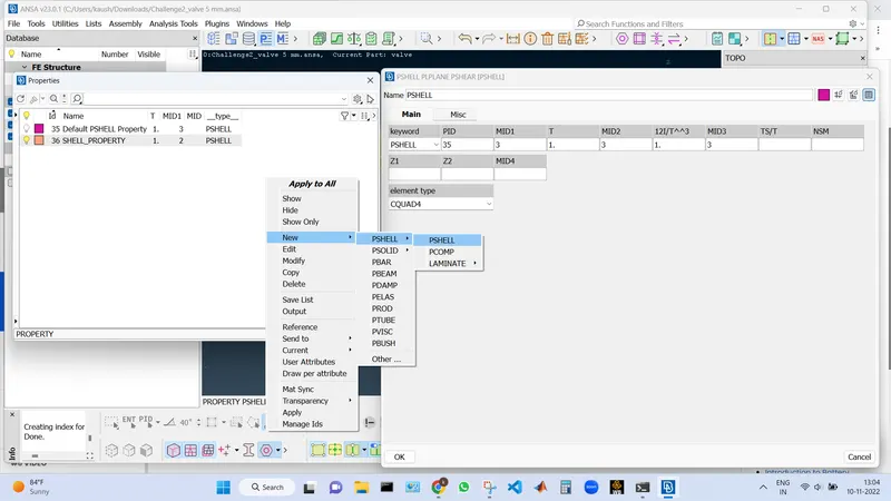
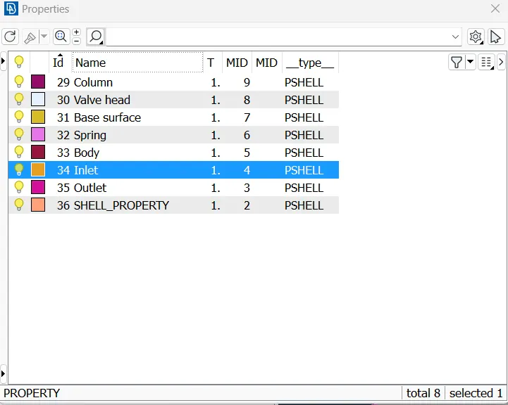
Create PID
Go toproperties>right click>New>pshell>pshell.
Created PID
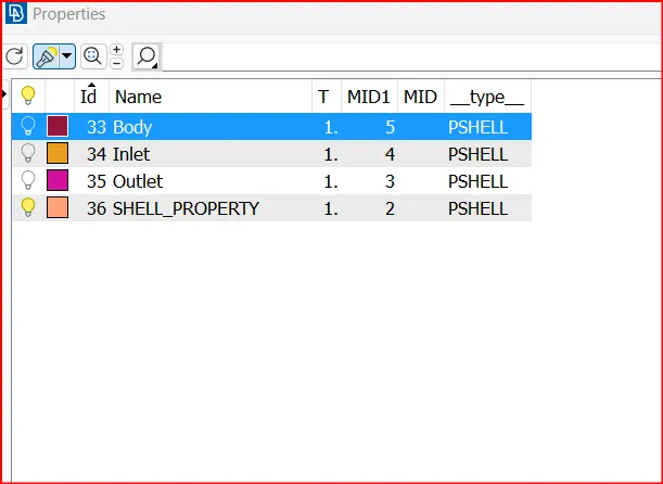
Now assign the components to the pid.
Select the pid>right click >apply>select the face by entity or pid region and middle click.
Like these all the faces are assigned to the following pids.
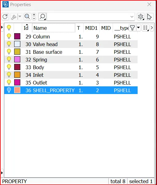
When we click on shell property in the pid manager still an edge is visisble
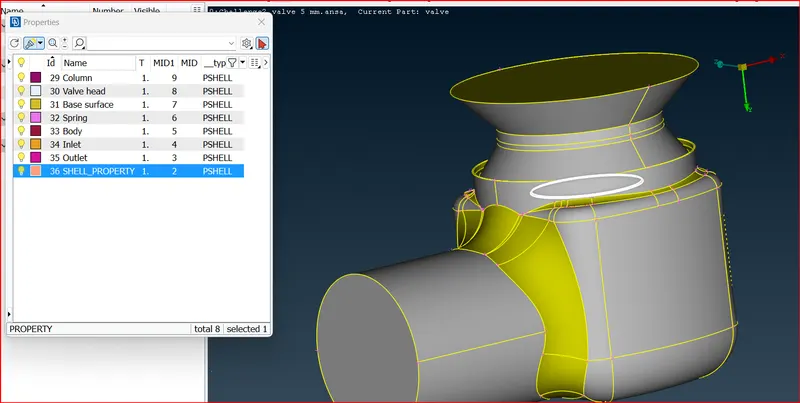
So we assign that surface to column pid.
Meshing:
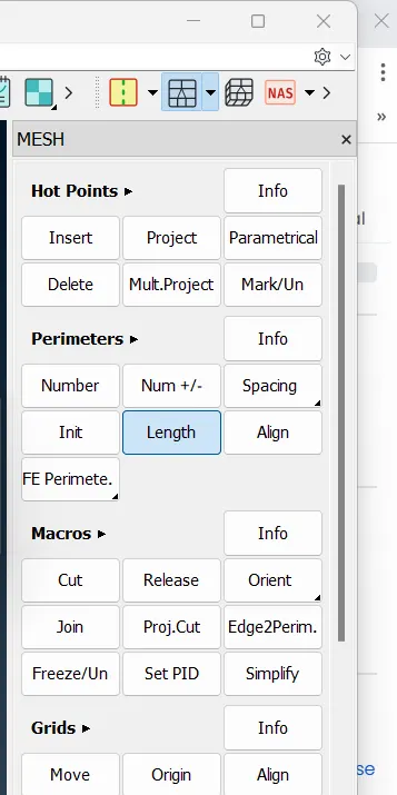
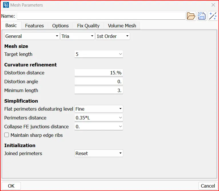
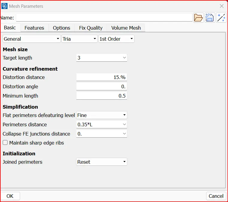
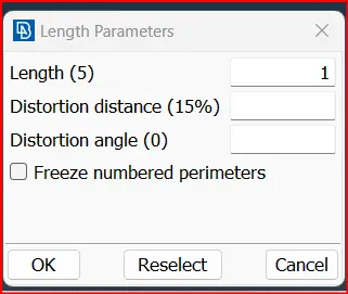
Mesh parameters
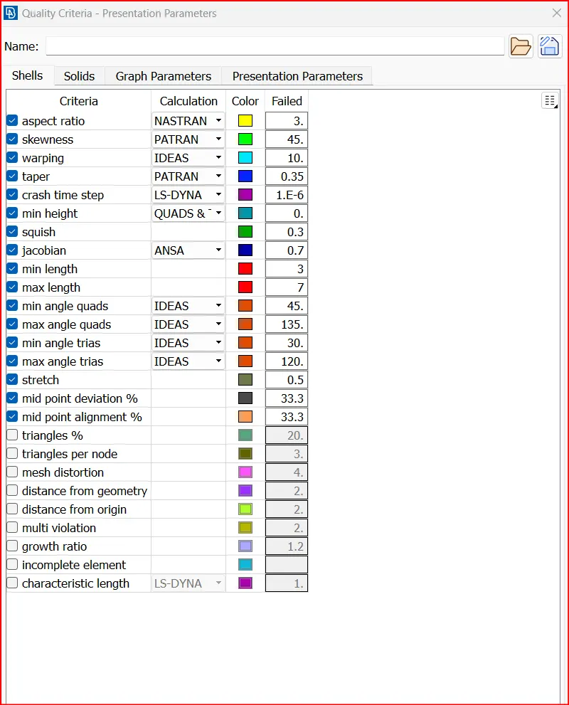
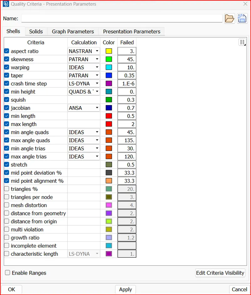
Mesh quality criteria
Now Go to spot mesh> select the faces and middle click to mesh them.
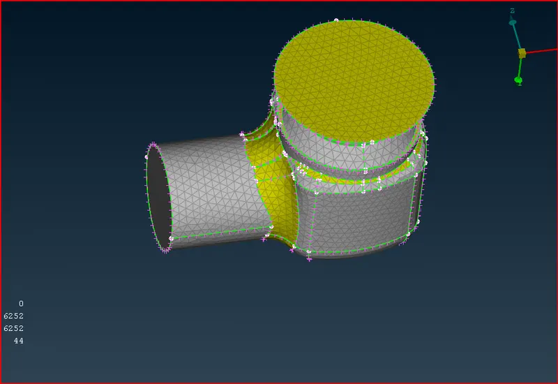
To Mesh this region:
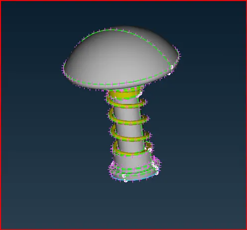
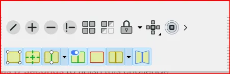
Use lock option to lock the view.
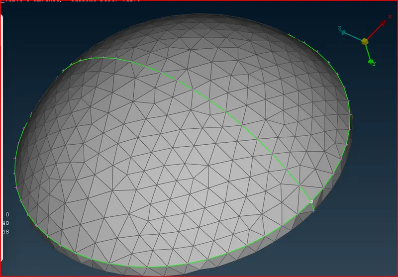
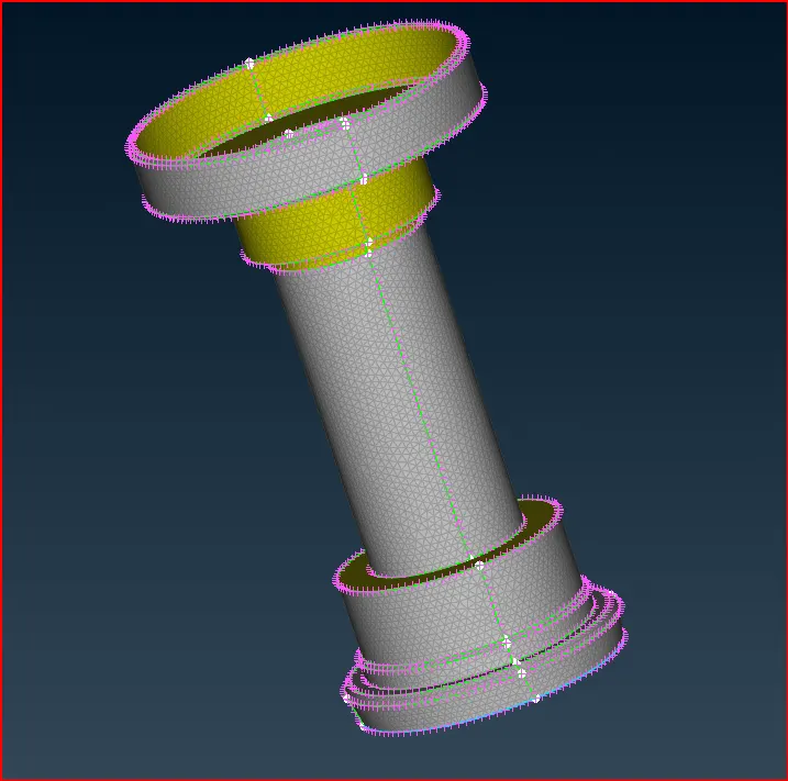
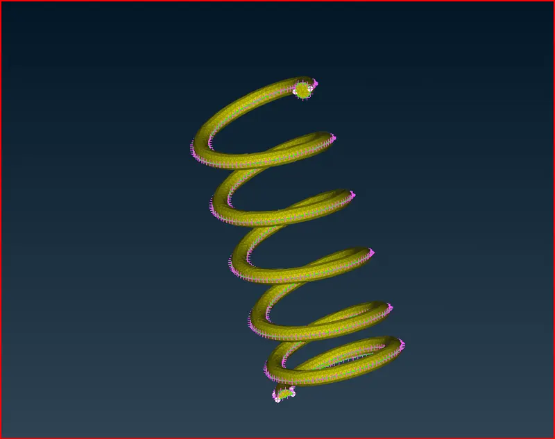
Now we can mesh the valve head, column and spring individually.
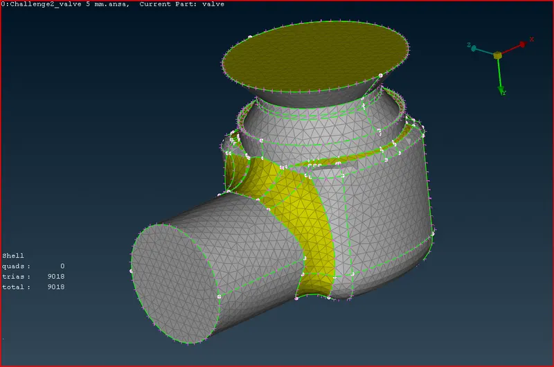
Valve head
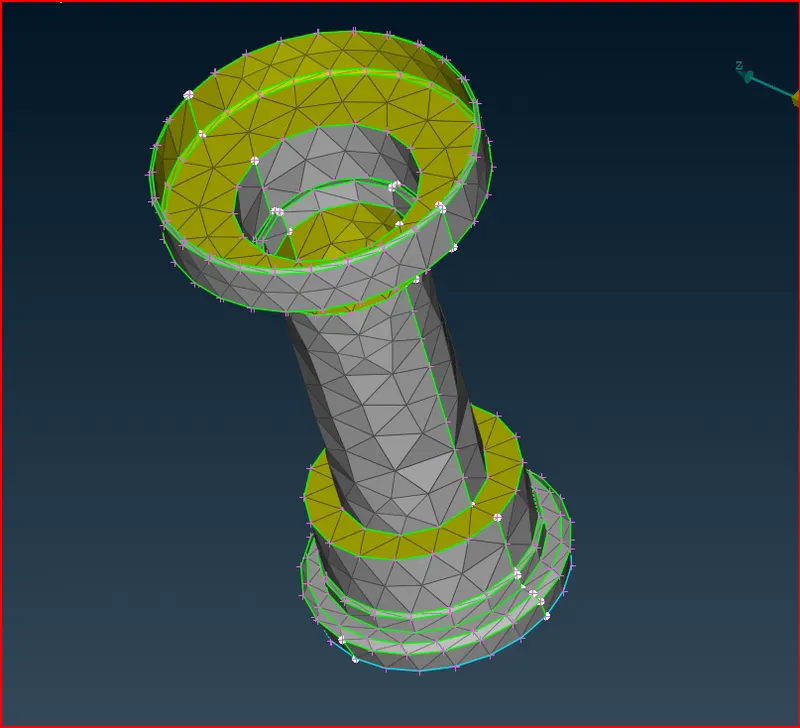
Column
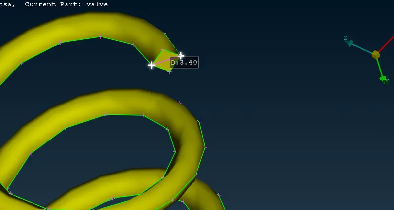
Spring
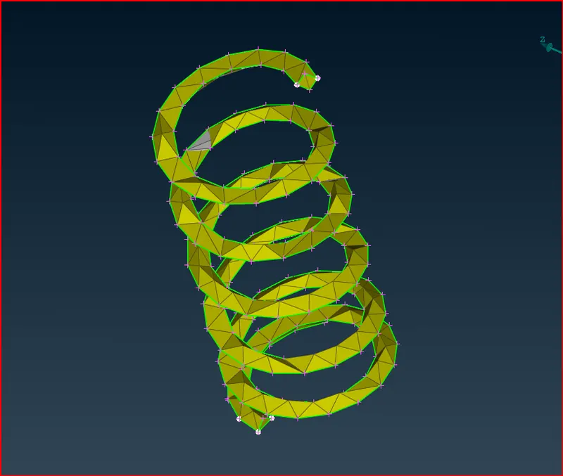
Complete geometry mesh with element size of 5mm.
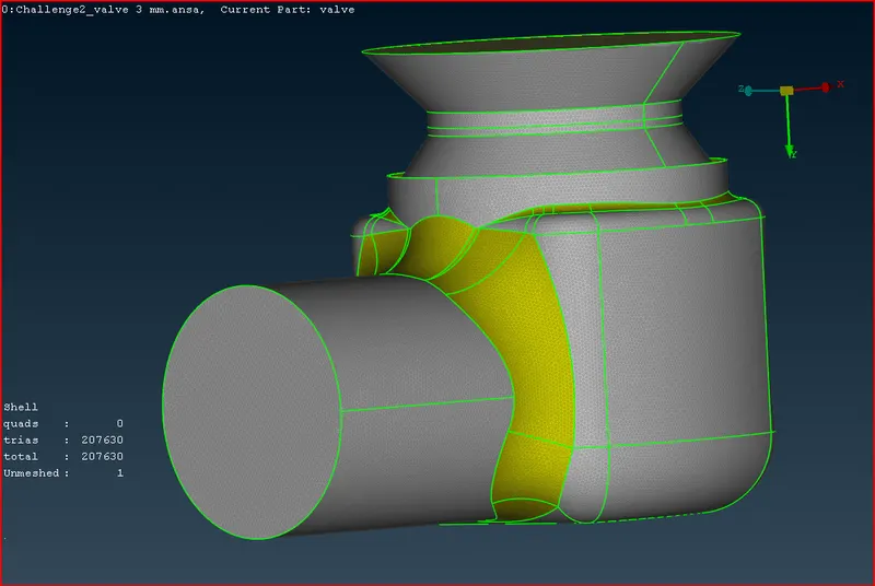
Mesh target length 3mm
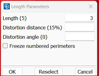
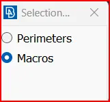
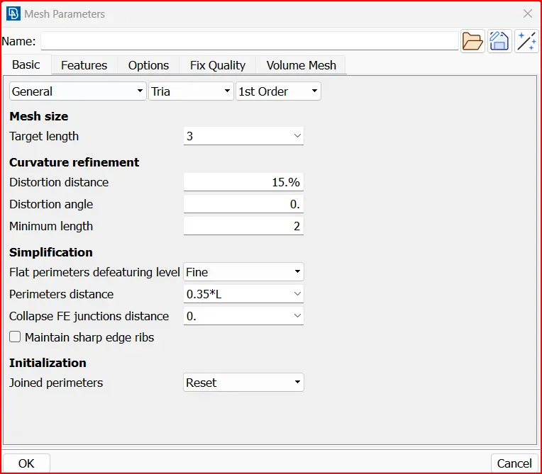
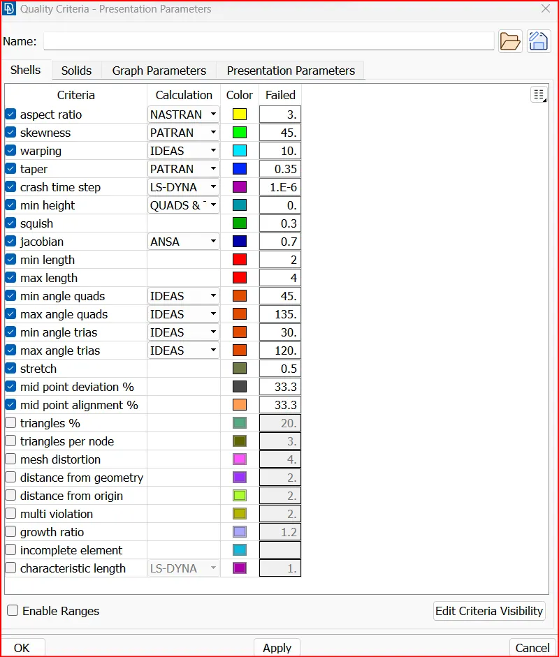
Now using spot mesh generate mesh on eah surface individually.
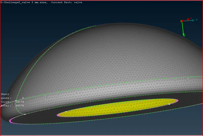
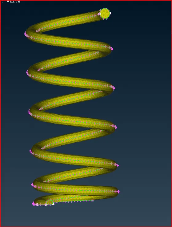
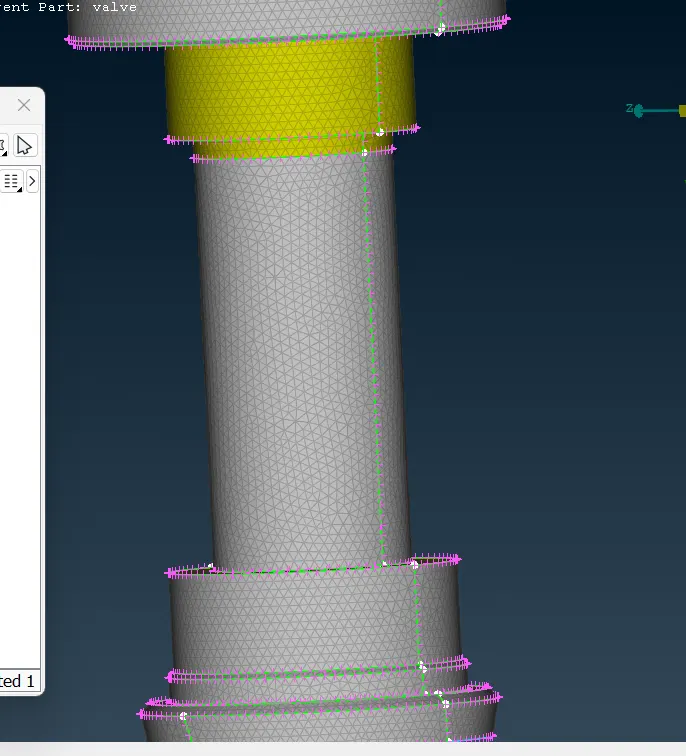
Final meshed geometry
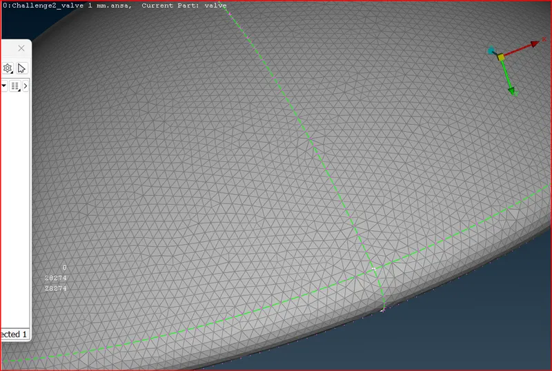
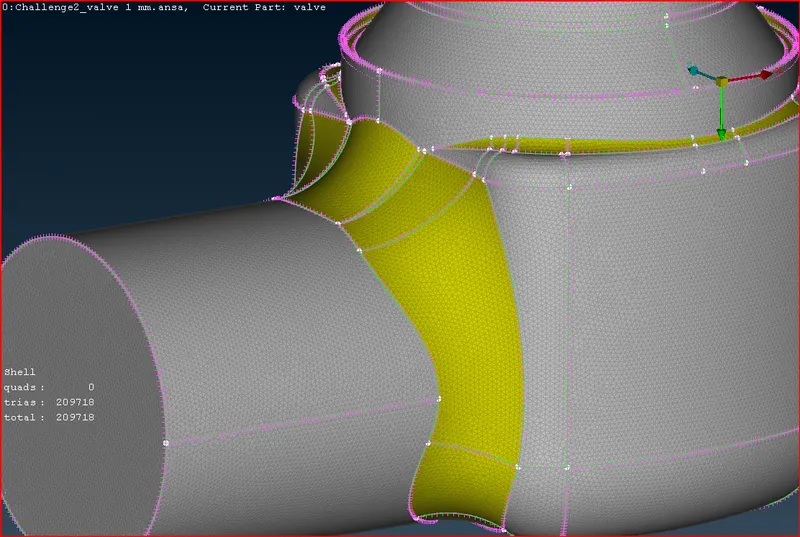
Mesh target length 1mm
Conclusion:
Geometry cleanup was done on the given component and missing surfaces were filled.
Multiple Pid was created to distinguish the indvidual components.
Mesh was generated individually on each component ranging from 5mm length to 3 mm and 1 mm length.
It was observed while meshing that as the target length was reduced from 5 mm to 3mm and to 1mm, the number of mesh elements increased, mesh quality improved.
By decreasing the element length, we were able to capture the geometry properly/ accurately like in the valve head the curvature appears smooth as we decrease the element size from 5 to 3 to 1mm.
even in spring for the 5 mm mesh size, the geometry is not captured properly since the diameter of the spring is approximately 3 mm.
Hence the minimum mesh target element size for the given geometry should be 3mm, and to get the best results it should be 1 mm.