Week 2 Challenge : Surface meshing on a Pressure valve
Report on Valve
Aim: To surface mesh a Valve using ANSA software
Procedure
- Upload the file in ANSA.
- be in TOPO mode and delete the unnecessary hot points by selecting delete command in hot point window and select the entire model with box select.
- Now check the geometry check, to find all the glitches, missing surfaces and bad cons
- now fill the surfaces or correct the surfaces. Can be done by using 2 ways
- Fill hole command in CONS section
- New command in Faces section.
- By selecting the suitable command to the surface, fill up all the cons and fill it completly.
- Existing surfaces, produces surfaces by taking reference from already existed face.
- Planar, produces in-plane surfaces.
- Fitted, produces surfaces right to the fit of boundaries
- Coons, produces surface by taking coons as boundaries.
- While using these correction commands, we can use either loop mode or entity mode, again depends on what kind of surface we are filling
Eg: Difference in surface formed while selecting in ‘LOOP’ mode Vs ‘ENTITE’ mode
Other observations while correcting
- Always Fill holes won’t work, need to choose the better option.
Below example, fill hole option give wrong results (fills inner holes). Whereas coons gives perfect output surface
- comparison of all surface commands
Below we can see, Coons and Fitted commands were also making the surfaces, but are not in right geometry.
With fitted option, may the surface in plane, but we can see the centre line hatches were not in centre, which means it making secondary surface.
So we went with fill hole command.
- at this corner, COONS command gave the best result.
- After completing/ filling out the errors, we need to assign the PID (property ID) to all the surfaces (one way to segregate the parts).
Figure shows error free cons
- it makes easy to hide or unhide the parts and easy to understand the model.
- initially system will assign a default IPD for a model, to create a new one select NEW in bottom and type name
- we can see the bulb is not functional beside the naming in the list, because we just prepared a list but not assigned to the model.
- To assign, select the name and press right click and choose ‘apply’ and select the surface and press middle mouse button.
- Now we recheck the errors by doing geometric check.
- We find intersection errors between spring and Coolum, to be removed.
14 either by making new cuts on spring and delete remains part or select the intersection command in Faces command box
- Intersection command will make a boundary between two parts.
- Automatically selects few intersection sections and ask for either delete or keep.
Can be clearly seen in wireframe mode in White colour
Accordingly delete or keep the surfaces.
- After selection, we do geometry check again and we can see no intersectional errors were left.
- The warning in geometry could be further reduced, by deleting the single coons.
By deleting the surface of single coons, warnings were reduce from 9 to 5.
- Meshing: here we have 3 different parameters to mesh and compare.
- with mesh target length 1mm and element type Tria
- with mesh target length 3mm and element type Tria
- with mesh target length 5mm and element type Tria
- Before the mesh we need to close all the surfaces of Valve.
- Go to Mesh property and give minimum and maximum target lengths as
|
For |
Min |
Max |
|
1mm Target length |
0.5 |
2 |
|
3mm target length |
2 |
4 |
|
5mm target length |
4 |
6 |
- Also specify the element type in mesh property.
- Now specify the same in quality of mesh command
- Give the parameters to the meshing, by selecting the length command in perimeter. Give parameter and coons.
- Now generate the mesh by selecting the SPOT mesh in mesh generation command block.
OUTPUT
26 repeat the steps from 19 for 3mm and 5 mm target length meshing.
Observation:
1 With lower target length, mesh is fine and producing complete meshing of all parts.
- As the target length decreases mesh quality decreases and no of tria elements increases and size of the file also increases.
|
For target length |
Elements |
File size |
|
1mm |
206275 |
21663 KB |
|
3mm |
23493 |
5039 KB |
|
5mm |
8790 |
3434 KB |
Difference in meshing on Spring.
In 5mm mesh made the spring as a surface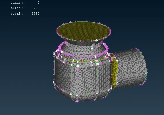
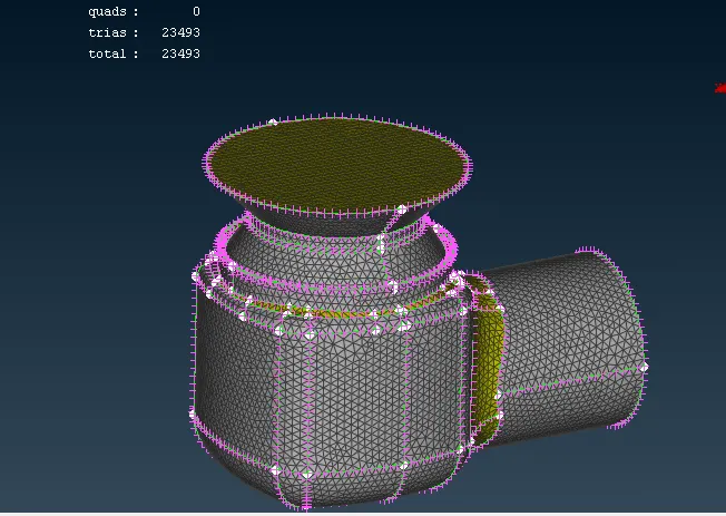
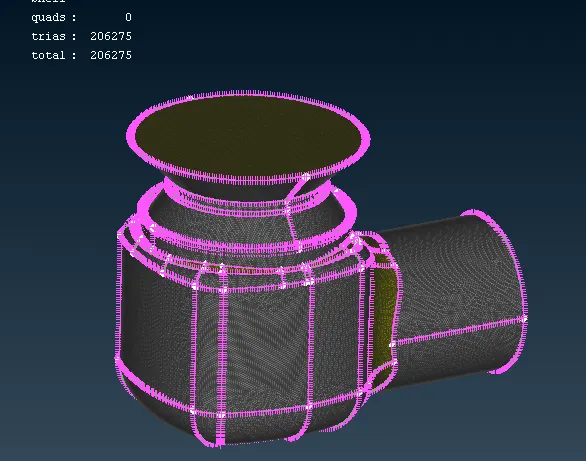
Result:
Among the above 3 meshes, 1mm target length is good for modelling. Because, as finer the elements the displacement results are more accurate.