Week 2 Challenge : Surface meshing on a Pressure valve
Objective: To clean up, the topology of the model provided in the challenge and mesh it with the optimum size of the mesh.
Process:
Import the model into the ansa workspace as shown in the figure below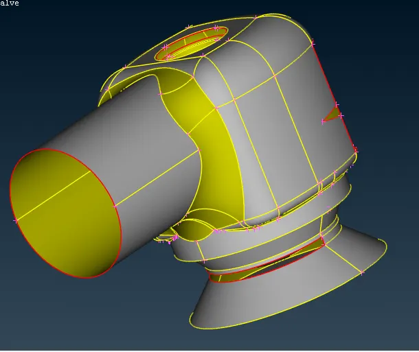
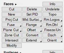
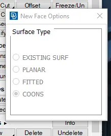
Using various tools the holes in the model are filled up. With the use of the new tool in the faces menu of the topology toolbar, the holes of the model are cleaned up. This tool has options available for the user to select from for the most suitable option to fill up the geometry the existing surf option would fill clean up the single cons using the existing geometry, and the planer option would use a flat surface to fill up the holes, fitted option would fill up the holes using a tangential surface to the adjacent faces and the conns option would use the selected cons to generate the surfaces parallelly or tangentially.
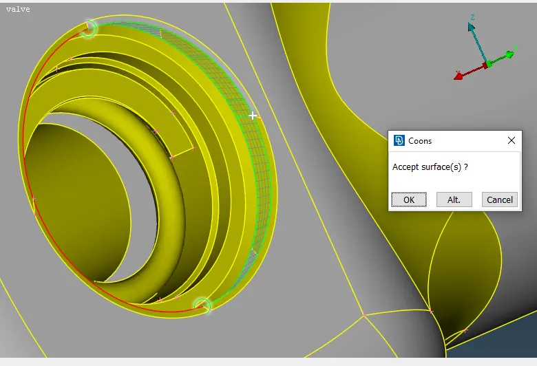
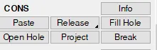
Another tool used to fill the holes is a Fill Hole tool in the cons menu of the topology toolbar
After filling the holes the surfaces of the model are cleaned up by removing any unnecessary cons because these cons would affect the uniformity of the mesh. To remove the unnecessary two surfaces attached to the cons are deleted using the delete of the face menu and then a new merged surface is generated for better topology.
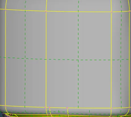
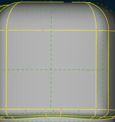
Another method of ignoring the unwanted cons is the join tool in the macros menu of the mesh toolbar this join tool would join the faces ignoring the cons in between the selected surfaces.
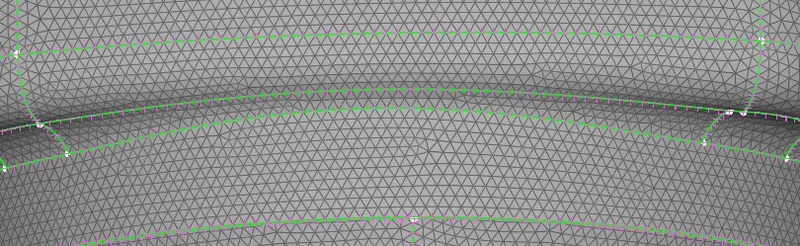
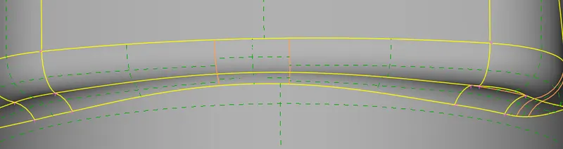
After cleaning the topology the negative and positive vector positions are oriented using the Orient tool in the faces menus of the topology toolbar. This orientation of the faces would help in deciding the direction of the mesh.
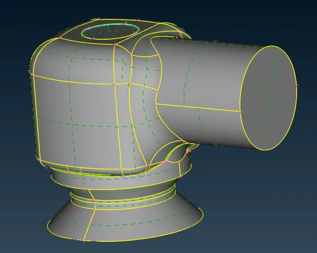
After orienting the geometry of the model is verified and ensured that the model doesn't possess any geometrical error which would lead to a meshing error.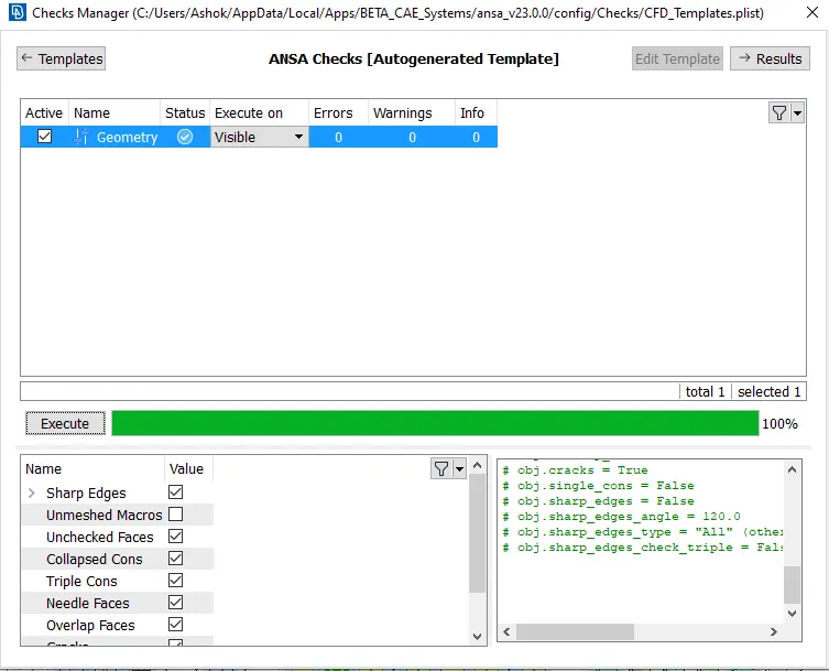
After verifying the geometry each part is assigned to a separate PID and this would help in the proper classification and visualization of the parts. This classification is done using the PID management tool and various selection tools discussed in the first challenge.
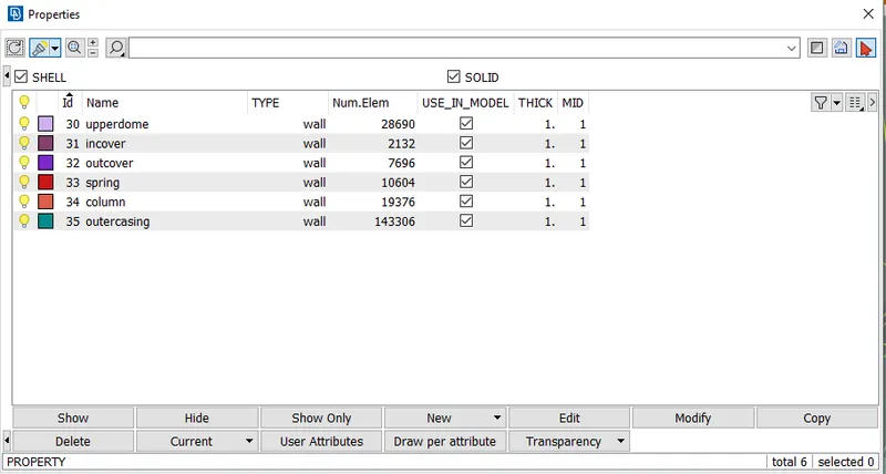
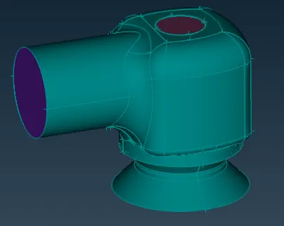
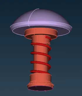
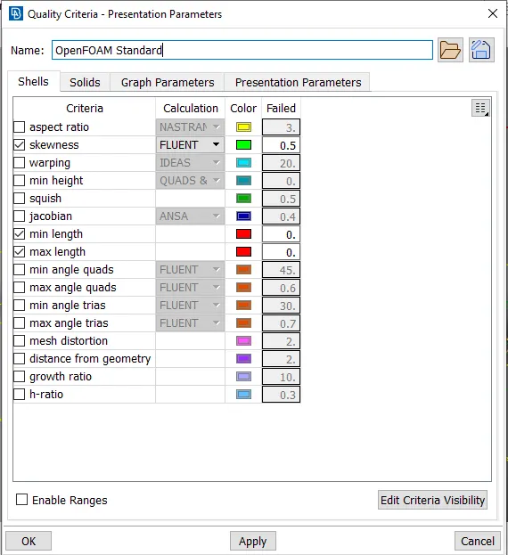
After segregating the parts meshing process is initiated. For this challenge as the mesh has to be of a certain size in the quality criteria section the max. length and min. length parameters are selected which would then be specified in the meshing parameters section.
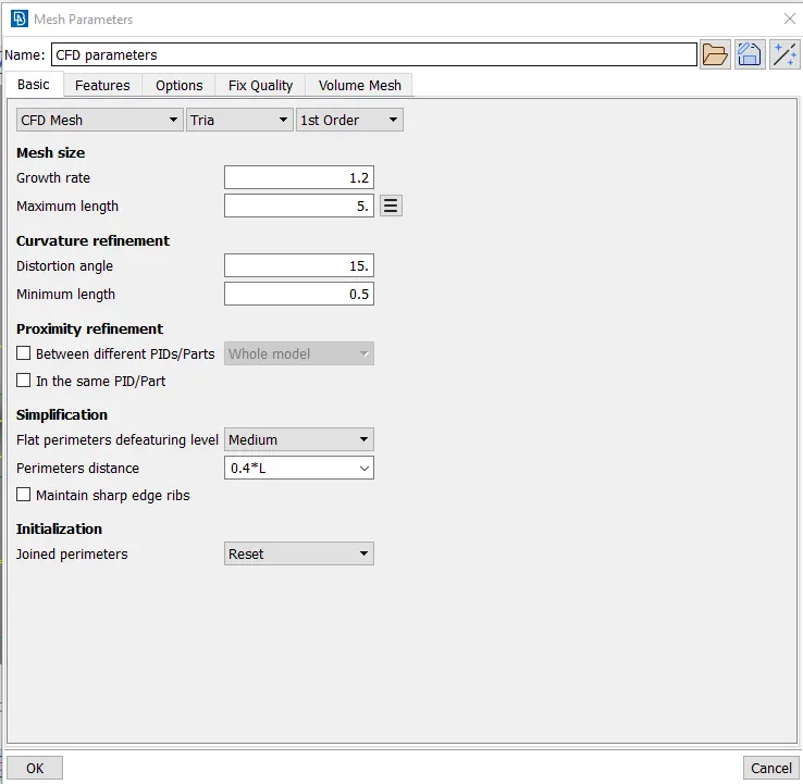
In the meshing parameter section, the geometry of the mesh is selected to be Tria as per the challenge requirement and the max. and min. mesh length values are entered as 5mm and 0.5 mm respectively.
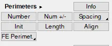
And then in the perimeters menu of the mesh toolbar length tool is used to define the target edges of the mesh.
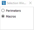
In the length tool, there are two options available i.e. perimeter and macros, the perimeters option is used to define the target length of mesh on the cons of the object and the macros option is used to define the target length of the mesh on the faces or surfaces of the object.
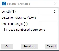
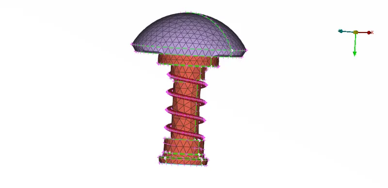
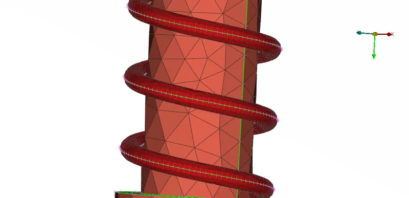
The target length of the mesh is varied according to the challenge i.e. 5mm, 3mm, and 1mm. Here the target length of the mesh of the spring of the valve is kept constant at 1mm because increasing the mesh length by more than 1mm distorts the geometry of the spring severely.
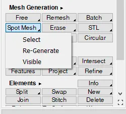
After setting the target length in the mesh generation menu spot mesh tool with a visible option is used to uniformly mesh the valve body.
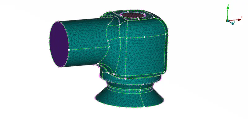
Mesh generated with a target length of 5mm is as shown in the figures below
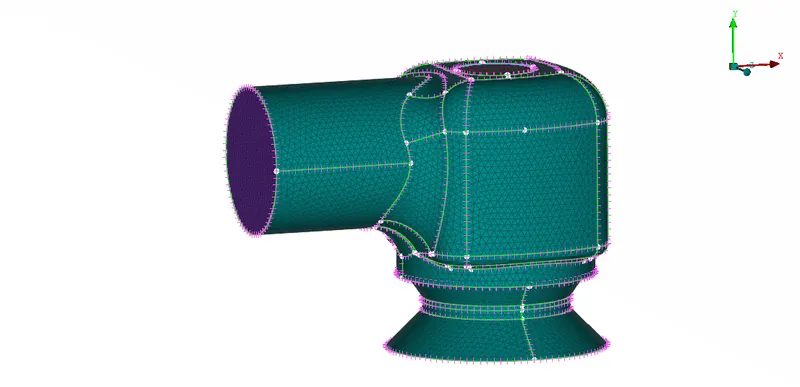
Mesh generated with a target length of 3mm is as shown in the figures below
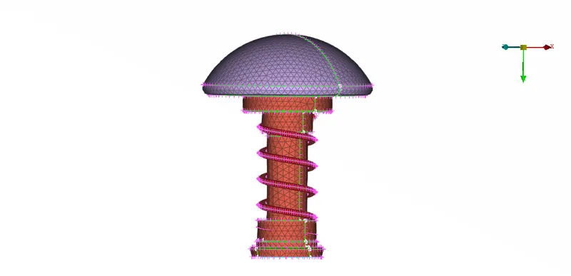
Mesh generated with a target length of 1mm is as shown in the figures below
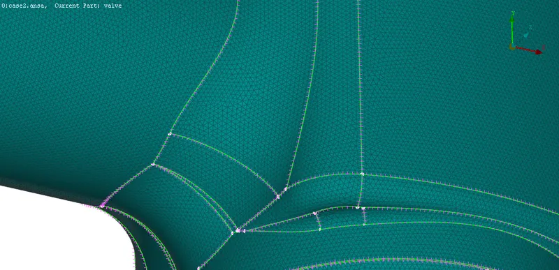
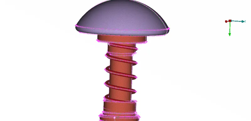
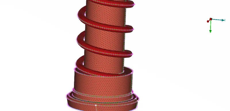
As it can be seen from the snapshot of the model reducing the target length of the mesh would result in a more accurate geometry of the model which would further enhance the accuracy of the results obtained by solving the CFD problems but the finer mesh would make a solution more complex and thus it would require higher processing power and longer time to solve those finer mesh problems. So optimum sized mesh is selected depending on the accuracy requirement of the results obtained and the type of the problem.