Week 2 Challenge : Surface meshing on a Pressure valve
AMI: Surface meshing of pressure valve with different target length.
. Target length = 1mm, 3mm and 5 mm ( i.e. 3 cases)
. Element type = Tria
Procedure:
- Topo- Cleanup:
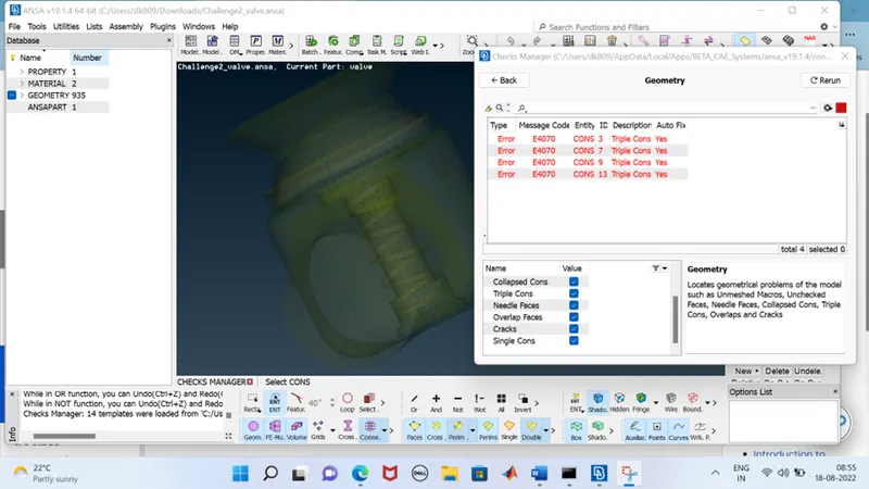
. The first thing needs to be done is to check for single cons and triple cons in the model. Single cons are cons that are shared with one surface only which indicates open surface. Such open surfaces are not expected in a closed geometry so that need to be resolved. Triple cons are formed due to con shared with three surfaces and that also need to be resolved on the basis of weather it is desired on that place or not Triple cons are not always errors but that shows the local volume may form due to those faces. These single and triple cons are identified using Geometric checks.
Surface meshing on a pressure value:
The whole process for Meshing is divided into
- Geomatical surface clean up
- Assigning properties for components of assembly
- Meshing for each component
For CFD analysis of any body, the body must not have any porous openings, in order to implement volumetric machina and analysis, hence visible presence of holes have to be closed and whole surface area has to generated without violating the uniformity and symmetricity of the geometry in question.
Geometrical Clean up:
Geometrical clean-up involves avoiding single CONS and holes in a body
Fig
Step 1: Observing and checking Single Cons:
One can observe single cons of a model by 2 ways:
Fig
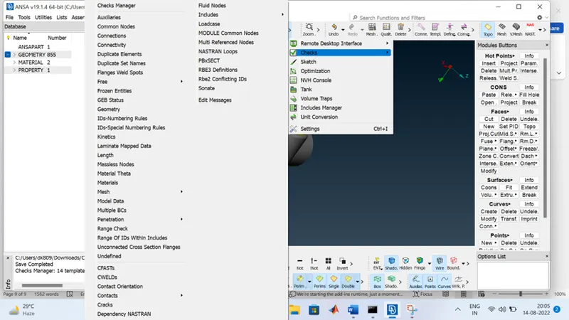
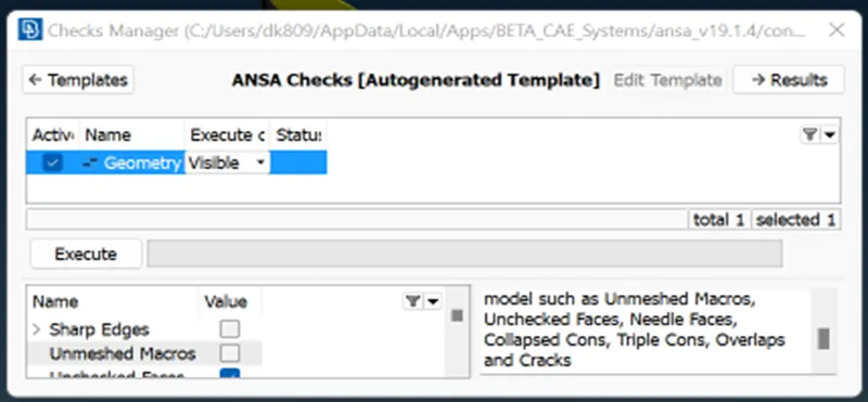
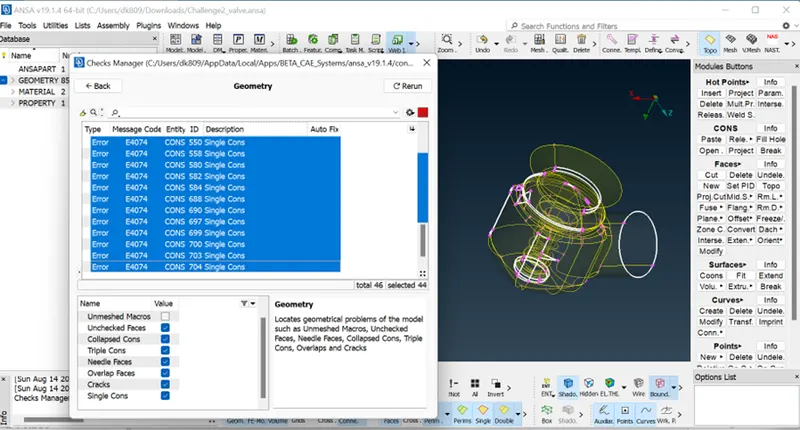
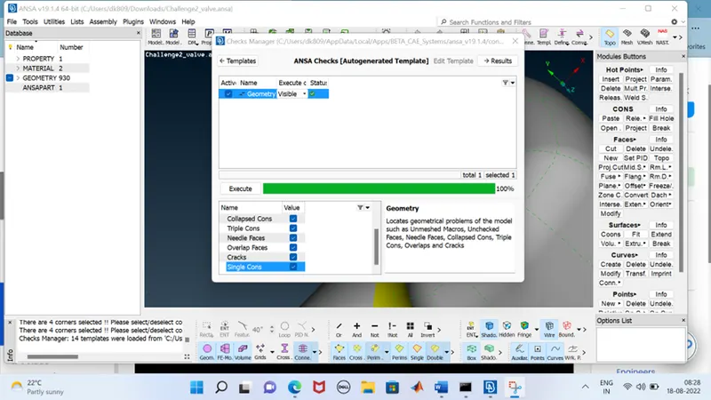
Go to Tools > Checks > Geometry
Fig.
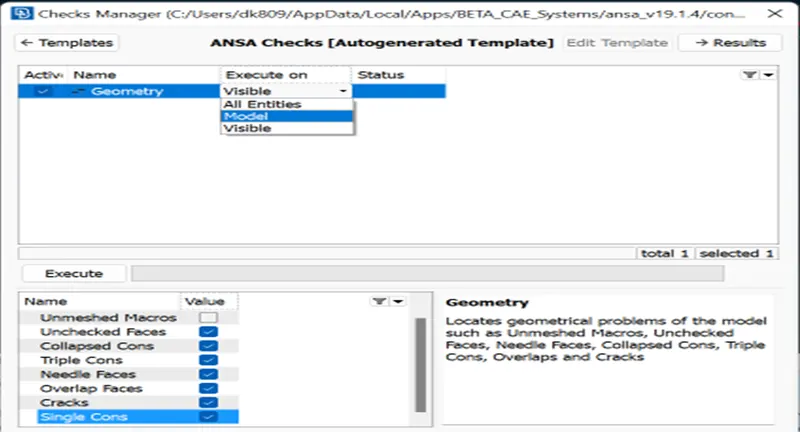
Now drag the option list and check single cons option
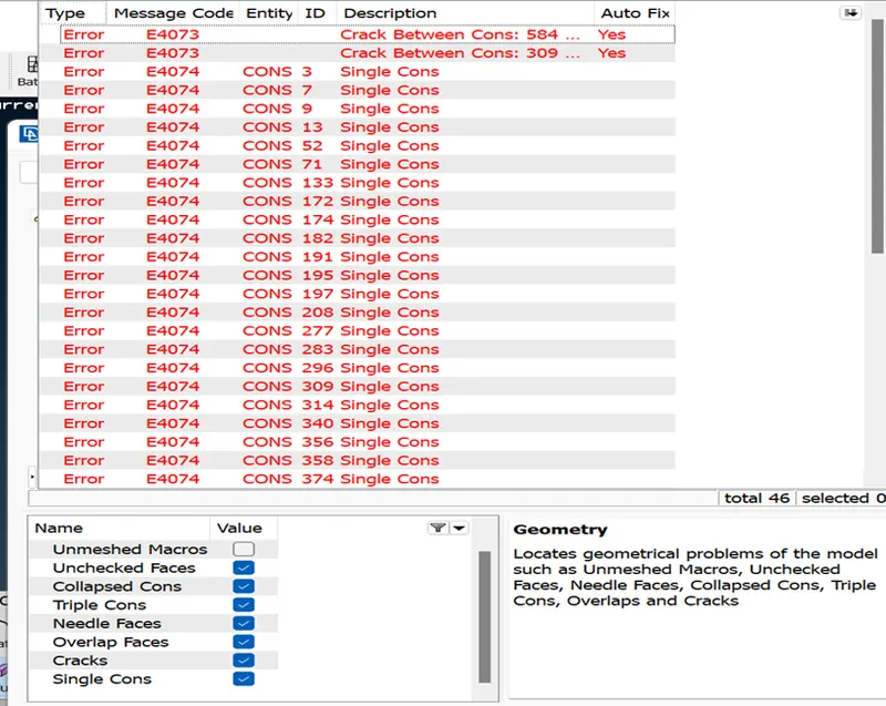
Now hit execute
Another way of checking cons is through wire frame mode
Uncheck Crosshair > Uncheck Double Cons > Uncheck Triple Cons >Uncheck shadow Mode (or hit CTRL + shift) for wireframe mode
Step 2: Single cons treatment:
After checking for Single CONs, one needs to resolve these by creating surfaces and filling holes wherever it is necessary.
Go to Topo > Faces > New
Fig
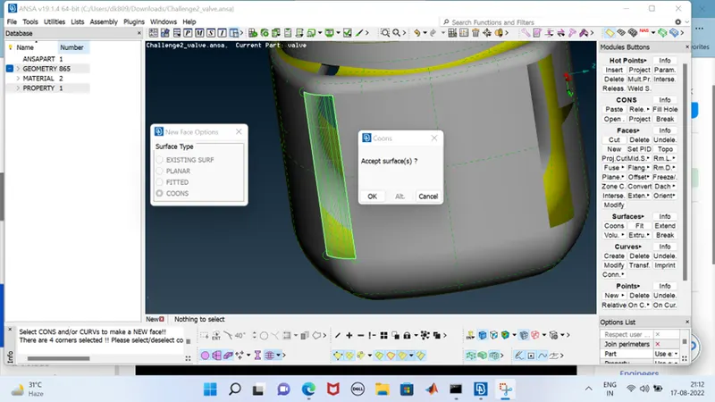
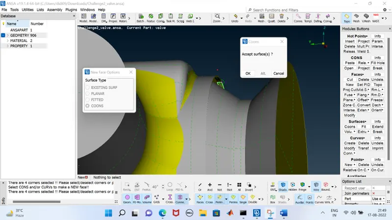
We are given 4 types of creating new faces. Currently, I’ve chosen coons option & checked loop for symmetrical single CONs entity
Hit COONs (Left Click) > Hit Loops (Left Click) > Select Entity > Right Click
Now we are given with a preview of the surface created using COONS and if the surface is acceptable for us & does not create any interference with neighbouring surfaces and shows uniformity, then it can be accepted.
Note:
For interfering surfaces while filling the holes with new faces, a separate treatment has to be done.
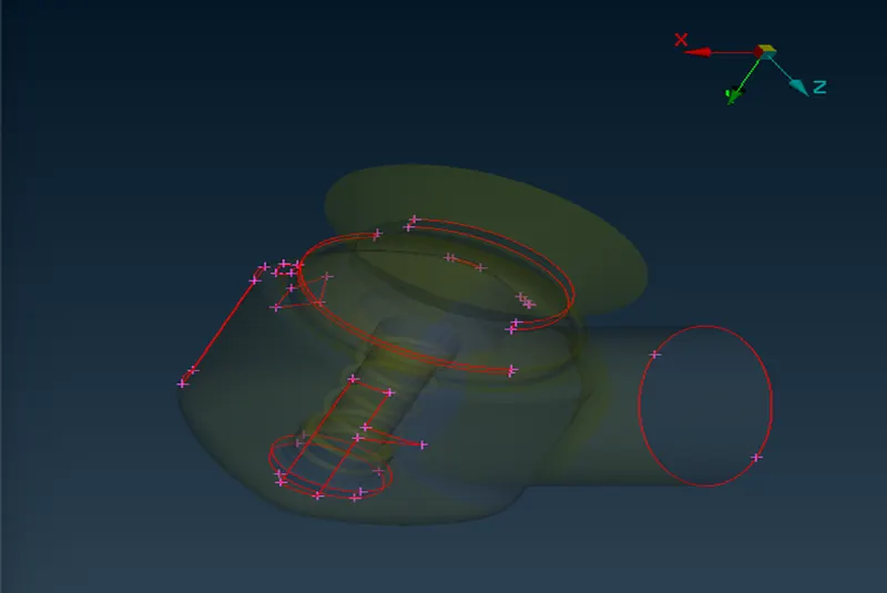
Ex: Below shape of the single CONs will lead us to interfering surface, if one uses LOOP as an option to select single CONS
Fig.
Therefore, one can select the single CON entity by diving the whole Single CON hole into 2 ways.
One needs to select Entity option before selecting the single CON surfaces.
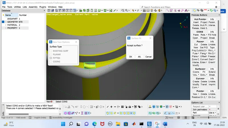
- Select the two opposite side of the triangular surface and form the surface from above method.
- Then select the whole left out rectangular surface and generate surface.
Fig.
Now one can clearly see that, there are no interfering non uniform surface in the preview.
Fig.
Note:
For single CONS for non-uniform length in a radial or circular environment, again choose entity option for selecting CONS. Avoid using LOOP in such cases.
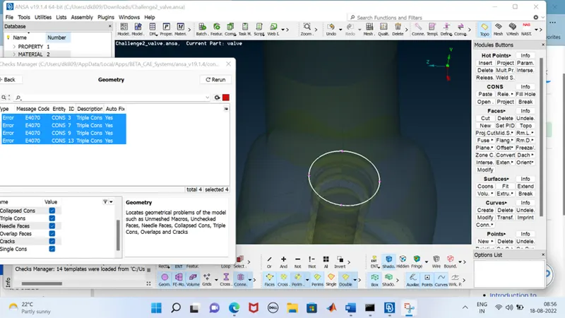
Blue colour on the surface indicates, that it’s a Triple CON, which in this case is not an error and doesn’t involve any non-uniform geometry surface.
This is due to coincidence of three surfaces on a single point
Fig.
Step 3: Smaller and interfering surface treatment:
One needs to also check for surfaces which are having very small surface areas. Unwanted Double CONs where its necessity is not validated must be removed, since this will be a problem for giving target length for meshing.
Fig.
Go to Topo > Faces > Cut.
- Now right click on the unwanted double cons to increase the surface area and to join the double con with the larger area itself
- You will be able to an orange line instead or yellow line which indicates the previous history of the line
- Similarly these steps have to be incorporated throughout the geometry of the surface.
Assigning properties for components of assembly:
The valve assembly comprises of
. Body
. Inlet
. Outlet
. Valve Head
. Valve Spring
. Column Support
. Base Surface
Fig.
Each of these components have to be isolated and meshed separately for convenience of further usage of these components.
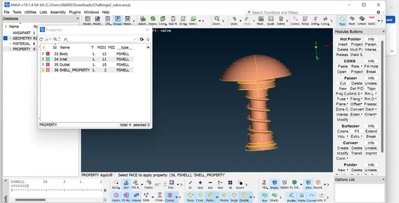
Assigning names for all these components help us bifurcate components easily and also to hide and show components easily.
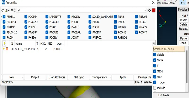
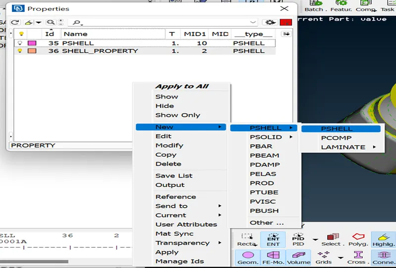
This is done using Property Manager.
Fo to Properties > Right Click > New > PShell > PShell
Fig.
A new box appears, where one can input the name of the properties to be listed. One has to input the name of the components for easy bifurcation and usage.
After creating properties for all components by naming & colour defining the geometry, one can proceed to the next step of Meshing
Meshing for each component:
Select and check the component to be meshed one by one using property manager. Meshing procedure is followed by
Go to Mesh > Perimeters > Length > Check Perimeters (In order to select the component fully, Press shift & drag the mouse)
- Input the target length as 5mm
Fig.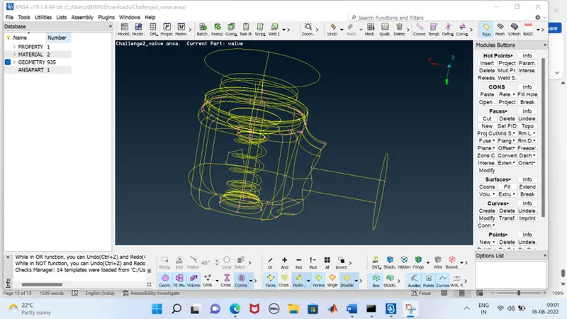
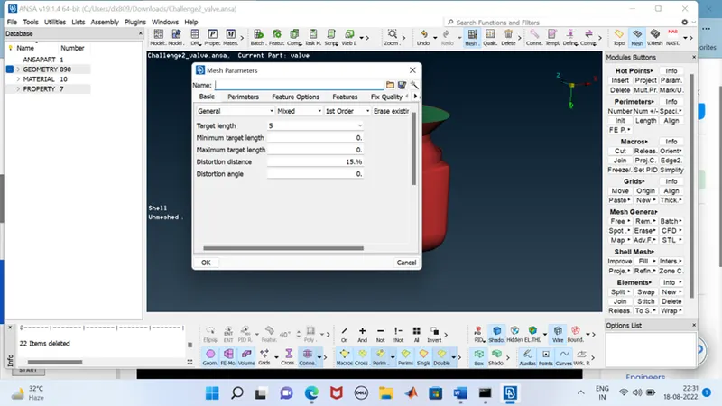
- Now Go to Utilities > Mesh parameters
Input the following as below:
- Target length = 5mm
- Minimum target length = 3 mm
- Maximum Target length = 7mm
Hit ok
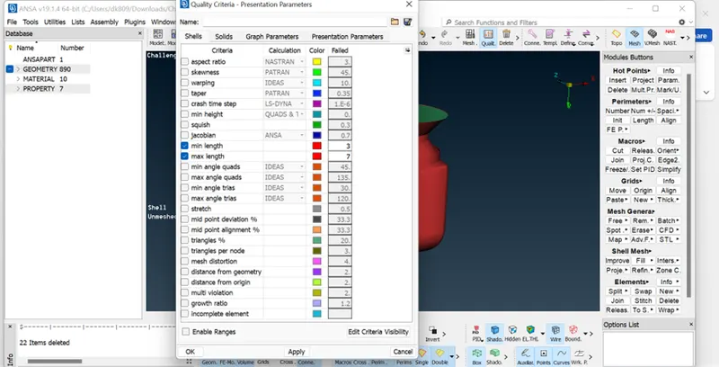
> Now Go to Utilities > Quality criteria > Check Min. Length (Also enter value as 3 mm) > Max. Length > (Also enter value as 5 mm)
Fig.
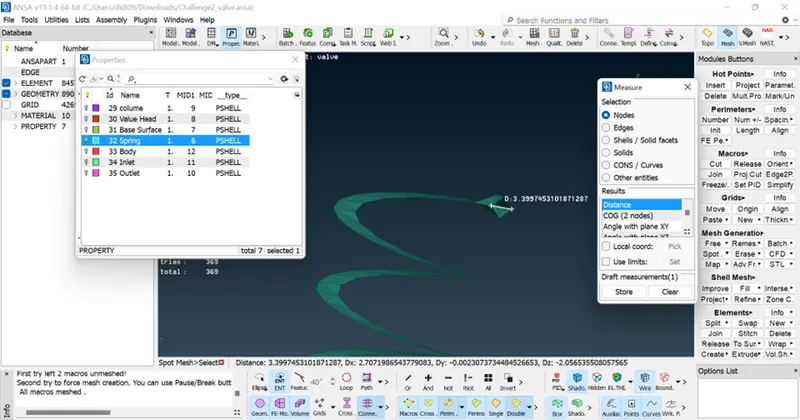
Now Go to Mesh Generation > Spot Mesh > Visible
Fig.
Interpretation:
Fig.
Conclusion:
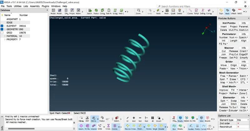
- For the geometrical components bearing lesser surface areas and indicate curve profile, meshing target length demands lesser magnitude in order to capture the profile of the geometry nearly equivalent to real life geometry equivalent.
- The reason behind this is geometry of the mesh element cannot bear curve or circular nature if the
Size of the element > Surface area
- Ultimately question arises on compromission of computational time by increasing the number of mesh elements.
Stats for exponential raise on number of mesh elements are as below
Fig.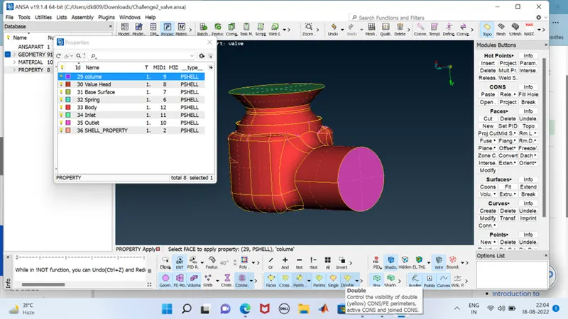
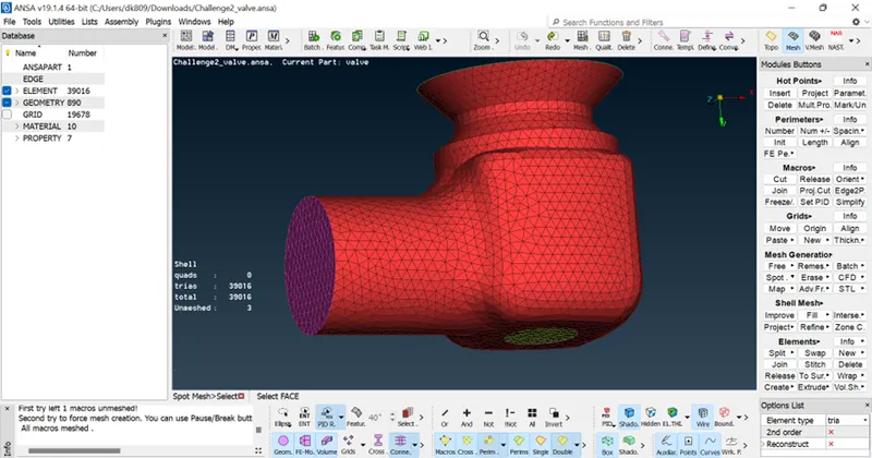
- Optimum way of reducing the number of mesh elements is to increase the meshing accuracy only for the geometrical surfaces of intricate and lesser surface area profiles which are continuously changing their profile.
- Target length as a parameter has to be treated as a Conditional format operator to have efficient usage wile analysis in CFD for saving computational Time.
- As mesh size becomes finer the number of cells increases rapidly. So, the different computational resources and computational cost.