Week 2 Challenge
Challenge 2: Live load Analysis
Aim: To apply a live load on the given bridge in Staad Pro using Australian vehicular loading.
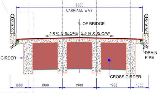
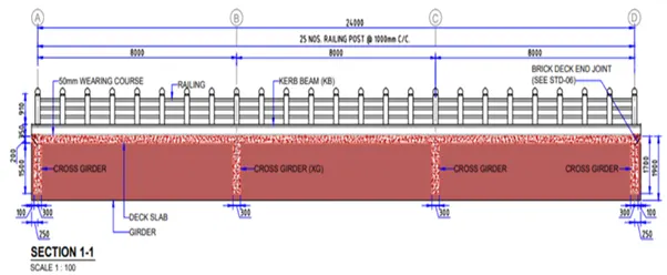
Introduction: This Challenge is focussed on how to apply the vehicle definitions and generate loadings for structural analysis of a bridge using the Staad Pro software. This study will provide a step-by-step procedure of designing a deck slab, I girders and the application of live loads. The Australian HLP 400 live loads have been considered in the design as per AS5100.2 and has been subjected on to the bridge. The end results would be analysing the structure and obtaining the critical shear forces and moments. The project is limited to applying the forces and obtaining the critical end results. Future recommendations can be done based on the further designing analysis.
Procedure:
Step 1: Analytical Modelling
Creating the nodes: A node has been created and projected 10m upwards. Both are combined using a beam element and the property of a pier needs to be defined. The 2m diameter of the pier has to be defined. This can be done using the properties tab, select the define tab and insert a 2m diameter. Once these has been initiated, the next step is to define the foundation. Create a mesh of 0.5m and add a plate element, now repeat the translation in X direction with 5 steps from the reference point and Z direction about 15 steps. Define the properties of these foundation, by clicking the supports, create and plate foundation by providing a subgrade modulus of 150kN/m/m.
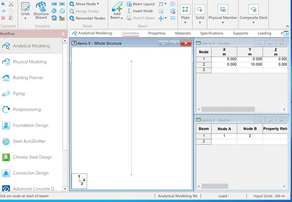
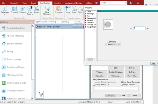
With this step a pier has been created with its properties assigned in Staad Pro. The next step would be creating a deck slab. To do this, we need to first create a mesh as described earlier of 0.5m x 0.5m and joining the nodes by adding a plate element. The deck slab properties has to be assigned following the same process. The thickness of the deck slab defined in this project is 300mm.
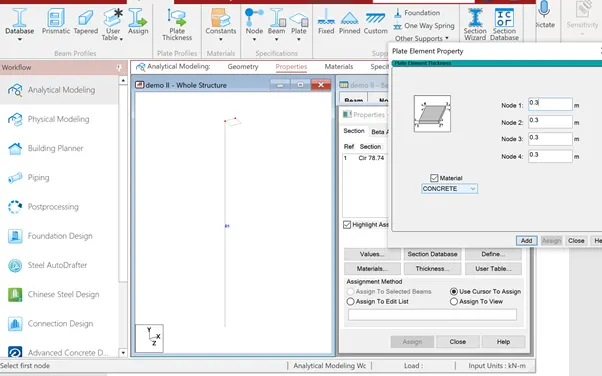
The above plate will be translated by 47 steps in span direction to create a deck slab span of 24m and will also be translated in Z direction 13 steps, i.e (7m carriage way divided by 0.5mesh will give us a value of 14, as one mesh is included already, we need to assign 13 steps in Z direction). Additionally, an offset on either sides of the carriage way has to be given for the allowance of footpath, kerbs and access of drain pipes. Once the deck slab has been created we need to define the foundation properties where the pier will be rested.
For this study, a raft foundation has been used. A plate mat of subgrade modulus 150kN/m/m has been assigned for the soil properties.
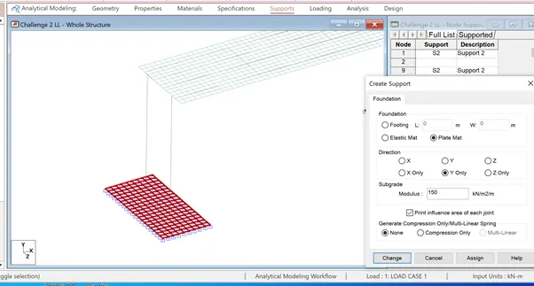
The next step is to create a longitudinal and cross girder. For this study, 4 longitudinal and 4 cross girders has been defined as shown in the figure below:
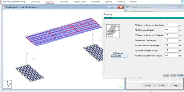
Tapered I girder properties has been assigned for longitudinal and cross girders. For this study purpose, same I girders have been assumed, which will not be in the real-world problems.
Once the girders, deck slab and foundation properties have been applied; the next step is to define loadings. Self-weight load has been defined for the whole structure.
Live Loadings:
For this study, Australian live loads of HLP400 which are the heaviest loads has been subjected on this deck slab.
HLP400 properties:
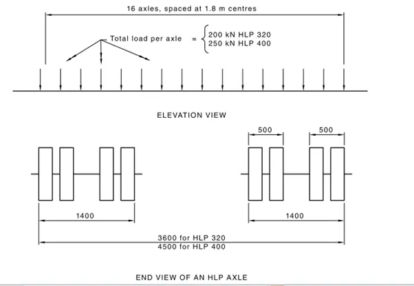
The 250kN, 16 axle loads with 1.8m centre to centre has been placed in the vehicle definition as shown in the figure below:
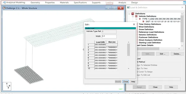
The width between the axle was determined by (4.5-1.4/2) where the loads will be acting centre to centre. The type 1 load is defined as HLP400. Once the vehicle is defined, load cases has to be applied. The first load case will be self-weight and the live loads shall be generated from by the following formula:
Loads generated = length of the vehicle + span length +0.5m increment = 105.6 approximately 106 generations have been created.
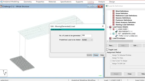
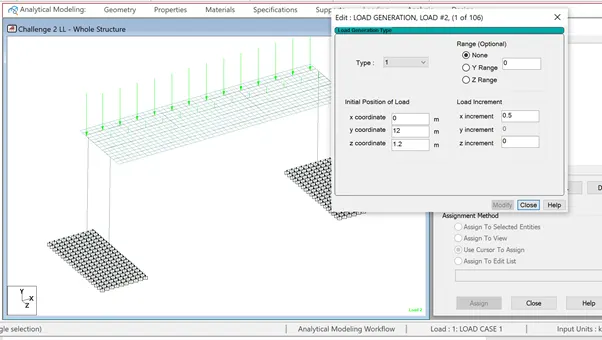
The load has been applied at an initial position of (0,12,1.2) and with a load increment of 0.5m.
The next step is to do the analysis. Run analysis and adding all the analysis criterions. Once, the analysis is performed a post analysis window pops up.
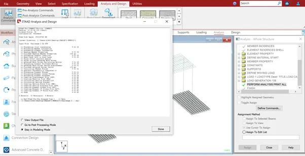
There are zero errors, once this has been achieved, we are good to go with post processing analysis to analyse the results.
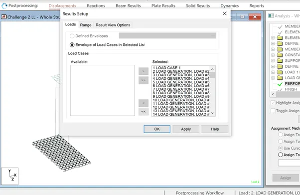
Results:
The displacement diagram has been generated as shown below:
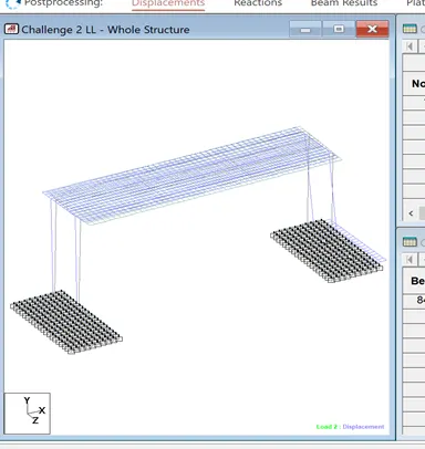
For instance for 2nd load generation and 37th load generation, the moment in Z direction has been shown:
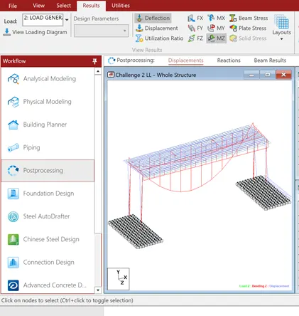
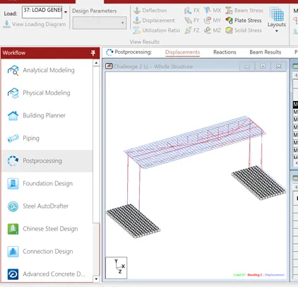
Similarly, 106 loads will be generated, and the most critical moment and shear has to be selected for further designing process. For this study purposes, the critical moment and shear for the girders and deck slabs have been shown below:
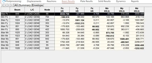
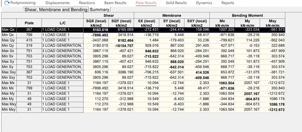
All the critical factors have been highlighted in black.
***END OF THE REPORT***