Week 2:- BiW Fixture Basics Challenge
1) What is the process of Project execution activity
PROJECT EXECUTION ACTIVITY
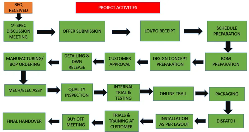
RFQ RECEIVED (REQUEST FOR QUOTATION)
- This is the first step in any project. RFQ stands for Request for Quotation.
- In this, customer specifies his requirements, specifications, etc.in form of documents or data.
- Customer also specifies its technical offer, commercial offer, how the project will be executed and timeline to complete the project.
1st SPEC DISCUSSION MEETING
- In this the documents are related technical offer, commercial offer, project execution.
- It consists of the timeline required to complete the project are prepared.
- Discussion is also based on the time required to 3D Design, Analysis of design, Drawing and Detailing, Manufacturing, Assembly & Commissioning, etc. is considered.
OFFER SUBMISSION
- Then the cost of all the operation is considered. By considering this kind of things, the offer is prepared and submitted to the customer.
LOI/PO RECEIPT
- The customer will study the offer submitted. He will also take quotations from others.
- The customer will study all the offers, compare offers & then select the one offer which suits best.
- The customer will generate PO means Purchase order to start the work.
SCHEDULE PREPARATION
- The Project officially starts after receiving the PO.
- The timeline is fixed so there should be plan to beat the deadline & to complete the project.
- All the activities step by step are taken into account like PO receipt, 1st meeting, design date analysis, 3D design preparation and Simulation, etc.
- The time required to finish the individual activity is calculated and it is calculated based on the above steps.
- The calculated results should beat the timeline and if not then the required modifications is done in schedule to beat the timeline of the project.
- We should always have some backup plan for this because due to some reasons our tasks not complete on the fixed date or the next date is dependent on previous task.
BOM PREPARATION
- BOM is referred as Bill of Material is prepared for the project like the Bill of parts, grippers, cylinders, motors, etc. which are required.
DESIGN CONCEPT PREPARATION
- The customer gives data or the specifications for the design.
- Based on that data design process is start which fulfills all the customer requirements.
CUSTOMER APPROVAL
- After designing the concept, the approval of the customer is required.
- Customer checks the design fulfills the requirements or not according to the technical offer.
- If all the requirements are fulfilled, the customer gives approval for the design or customer will also ask for some addition or the changes in the design.
- By making the necessary changes, final approval is taken from the customer.
DETAILING AND DWG RELEASE
- After the approval from the customer, drawings are released which shows the detailed specifications of all the parts required such as dimensions, Quantity, Specifications, etc.
MANUFACTURING BOP ORDERING
- The BOP (Bill of Parts) like motors, cylinders, sensors, grippers, etc. required for manufacturing are ordered as per the design specifications.
MECHANICAL/ ELECTRICAL ASSEMBLY
- Once the parts are received, they will undergo the prior quality control checking.
- In this all the parts are checked as per the specification.
- After QC checking the mechanical or electrical assemblies are prepared as per the design.
QUALITY INSPECTION
After assembly, the material again is quality checked. In this all the dimensions, positional accuracy, Coordinates are checked by using CMM machine.
INTERNAL TRIAL AND TESTING
- After QC, the internal trials are taken to check the fixture can do the operation or not for what it is designed.
- The simulation is done for this purpose at early stage.
- In this the fixture is checked for the clamping of the part, welding, proper loading & unloading of the part, etc.
ONLINE TRIAL
- Online trial is taken in which all the operations done in automated mode by using electrical connections.
- The process sequence is checked as per the defined way in design in automated mode.
- Customer is also involved in online trial for taking the approval.
PACKAGING & DISPATCH
- The assemblies are packed in proper manner because in transportation the fixture will be damaged and hence the geometry of the fixture & also the functionality of the fixture will be affected. So, the packaging is very important.
- Once the packaging is done, the fixture is dispatched to the customer address.
INSTALLATION AS PER LAYOUT
- Layout is the space defined for the parts like fixture, robots, etc. according to the functionality, application, process sequence, etc.
- The layout is done at very initial level & according to that installation is done.
TRIALS & TRAINING AT CUSOMTER
- Production trials are taken at customers end.
- In technical offer we have specified the quality benchmarks for the fixture, the capability of the fixture for productions, etc.
- The trials are taken to check the capability of the fixture.
- Once it is done, then training is given to the operator, staff & engineer for the process sequence, how the fixture works, loading & unloading of the part, etc.
BUY OFF MEETING AND FINAL HANDOVER
- After productions trial & training, Customer check all the prescribed things in the offer are done or not.
- Sometimes customer also requires the additional work, so according to the requirement all the points are closed.
- After that, Project is finally handed over to the customer.
2) What are the types of joining processes?
- Joining process are the processes that are used for joining metal parts.
- Also defined as joining of two metal parts either temporarily or permanently with or without the application of heat or pressure.
There are two types of joining process such as
- Metallurgical Joining
- Mechanical Joining
METALLURGICAL JOINING
- Metallurgical joining includes fusion welding, pressure welding and brazing/ soldering which use different energies.
- There are also methos of chemical joining that use adhesives.
- There are different types of metallurgical joining are described below
1) WELDING
- Welding is a joining process whereby two or more parts are fused together by means of heat, pressure, or both forming a join as the parts cool.
- Welding is usually used on metals and thermoplastics but can also be used on wood. The completed welded joint may be referred to as a weldment.
- Welding works by joining two materials together without a separate binder material.
- Unlike brazing and soldering, which use a binder that has a lower melting point, welding joins the two workpieces directly together.
- Most welding done today falls into one of two categories: arc welding and torch welding.
- Arc Welding uses an electrical arc to melt the work materials as well as a filler material (sometimes called the welding rod) for welding joints.
- Arc welding involves attaching a grounding wire to the welding material or other metal.
- Another wire known as an electrode lead is placed on the material to be welded. Once that lead is pulled away from the material, an electric arc is generated.
- It’s a little like the sparks you see when pulling jumper cables off a car battery. The arc then melts the workpieces along with the filler material that helps to join the pieces.
- Feeding the filler into the welding joint takes steady hands and an eye for detail. As the rod melts, the welder must continuously feed the filler into the joint using small, steady, back-and-forth motions. These motions are what give welds their distinctive appearance. Going too fast or slow, or holding the arc too close or far away from the material can create poor welds.
- Shielded Metal Arc Welding (SMAW or Stick Welding), gas metal arc welding (more commonly known as a metal inert gas, or MIG welding), and gas tungsten arc welding (frequently called tungsten inert gas, or TIG, welding) all exemplify arc welding.
- These three common methods each offer unique advantages and drawbacks. Stick welding, for instance, is inexpensive and easy to learn.
- It’s also slower and less versatile than some other methods. Oppositely, TIG welding is difficult to learn and requires an elaborate welding rig.
- TIG welding produces high-quality welds, however, and can weld materials that other methods can’t.
- Torch weldingrepresents another popular welding method. This process typically uses an oxyacetelyne torch to melt the working material and welding rod.
- The welder controls the torch and rod simultaneously, giving him or her a lot of control over the weld.
- While torch welding has become less common industrially, it’s still frequently used for maintenance and repair work, as well as in sculptures.
- Thus, the welding process may be optimized (by optimizing heat generation, metal compositions and cooling rates) in order to minimize microstructural changes and residual stresses in the welded joints.
- Post - welding treatments are also often performed to relieve residual stresses and make the microstructure of the welds more uniform.
2) BRAZING
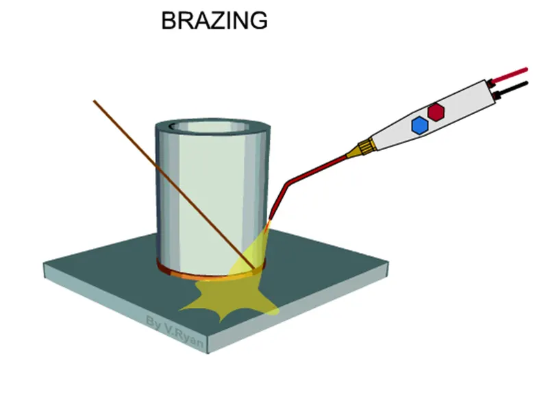
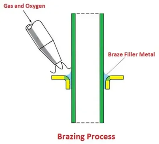
- Brazing is a metal-joining process in which two or more metal items are joined together by melting and flowing a filler metal into the joint, with the filler metal having a lower melting point than the adjoining metal.
- Brazing differs from welding in that it does not involve melting the work pieces.
- Brazing differs from soldering through the use of a higher temperature and much more closely fitted parts than when soldering.
- The materials used as filler for brazing are those that melt above 450 deg Celsius.
- During the brazing process, the filler metal flows into the gap between close-fitting parts by capillary action.
- The filler metal is brought slightly above its melting (liquidus) temperature while protected by a suitable atmosphere, usually a flux.
- It then flows over the base metal (in a process known as wetting) and is then cooled to join the work pieces together.
- A major advantage of brazing is the ability to join the same or different metals with considerable strength.
3) SOLDERING
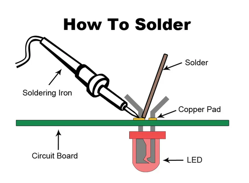
- Soldering is a joining process used to join different types of metals together by melting solder.
- Solder is a metal alloy usually made of tin and lead which is melted using a hot iron.
- The iron is heated to temperatures above 600 degrees fahrenheit which then cools to create a strong electrical bond.
- Solder is melted by using heat from an iron connected to a temperature controller.
- It is heated up to temperatures beyond its melting point at around 600 degrees fahrenheit which then causes it to melt, which then cools creating the soldered joint.
- As well as creating strong electrical joints solder can also be removed using a de-soldering tool.
- Solder is a metal alloy used to create strong permanent bonds; such as copper joining in circuit boards and copper pipe joints.
- It can also be supplied in two different types and diameters, lead and lead free and also can be between .032” and .062”.
- Inside the solder core is the flux, a material used to strengthen and improve its mechanical properties.
- Filler metals used in soldering were once lead based (lead solder), however, owing to regulations, lead-based solders are increasingly replaced with lead free solders, which may consist of antimony, bismuth, brass, copper, indium, tin or silver.
- Residues from fluxes, however, must be removed after soldering to reduce the risk of occurrence of corrosion.
4) ADHESIVE BONDING
- Adhesive Bonding is the process of joining two surfaces together, usually with the creation of a smooth bond.
- This may involve the use of glue, epoxy, or one of a wide range of plastic agents which bond either through the evaporation of a solvent or through curing via heat, time, or pressure.
- Glues have tended to create relatively weak joins but with the use of new self-curing adhesives these bonds are now close to the strength of the materials themselves.
- As a result, gluing is now the preferred method of joining for many applications, particularly when the bond is not exposed to prolonged heat or weathering.
- Many modern glues are carbon-based petrochemical derivatives, which can be used for a variety of joining applications including bonding metal and dissimilar materials.
- This type of adhesive uses either direct contact or a third surface, such as an adhesive tape, to create the bond.
- Among the composite applications that are commonly bonded using adhesives are fibreglass, and fibre-epoxies like boron-epoxy and carbon-epoxy.
- Due to their shear strength and toughness, modern adhesives can also serve to join structural materials, of which plywood is a common and well-known example.
- To maximize adhesive bonding strength, surfaces to be joined by adhesives must be cleaned thoroughly.
- This, in essence minimizes the interface gap between the adhesive and adherent.
- Making the surface rough also improves adhesive bond strength because of the mechanical interlocking that the roughness provided.
5) DIFFUSION BONDING
- Diffusion bonding or diffusion welding is a solid-state welding technique used in metalworking, capable of joining similar and dissimilar metals.
- It operates on the principle of solid-state diffusion, wherein the atoms of two solid, metallic surfaces intersperse themselves over time.
- This is typically accomplished at an elevated temperature, approximately 50-75% of the absolute melting temperature of the materials.
- Diffusion bonding is usually implemented by applying high pressure, in conjunction with necessarily high temperature, to the materials to be welded; the technique is most commonly used to weld "sandwiches" of alternating layers of thin metal foil, and metal wires or filaments.
- Currently, the diffusion bonding method is widely used in the joining of high-strength and refractory metals within the aerospace and nuclear industries.
- Diffusion bonding is capable of joining a vast array of combinations and sizes of metal and ceramic parts.
MECHANICAL JOINING
- Mechanical joining is a process for joining parts through mechanical methods, which often involve threaded holes.
- Joining parts using screws or nuts and both bolts are common examples of mechanical joining.
- The threaded holes employed for mechanical joining are vulnerable to fractures.
- In ductile materials, the fracture can come from fatigue, while in brittle materials, the fracture can simply result from mechanical overloading.
- Thus, mechanical joints must be designed with fatigue failure and brittle fracture in mind.
- Another issue to be considered when designing mechanical joints is galvanic corrosion, which is a type of corrosion that affects different types of metals that are in contact with each other.
3) What is Resistance welding and its application in the automotive sector?
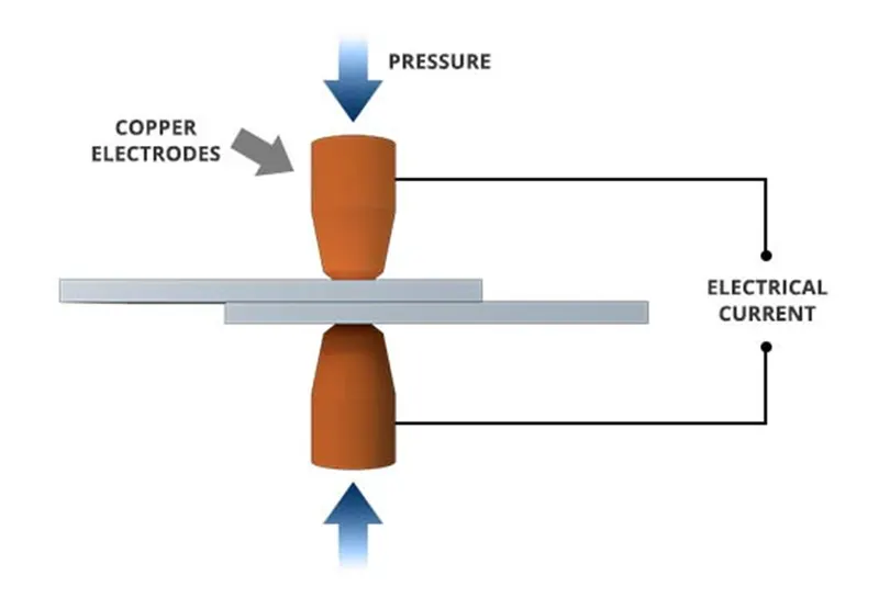
- Resistance welding is the joining of metals by applying pressure and passing current for a length of time through the metal area which is to be joined.
- The key advantage of resistance welding is that no other materials are needed to create the bond, which makes this process extremely cost effective.
- There are several different forms of resistance welding (e.g. spot and seam, projection, flash, and upset welding) which differ primarily by the types and shapes of weld electrodes that are used to apply the pressure and conduct the current.
- The electrodes, typically manufactured from copper based alloys due to superior conductive properties, are cooled by water flowing through cavities inside the electrode and the other conductive tooling of the resistance welding machine.
- Resistance welding machines are designed and built for a wide range of automotive, aerospace and industrial applications.
- Through automation, the action of these machines is highly controlled and repeatable allowing manufacturers to staff production readily.
Types of Resistance Welding Applications:
Spot Welding and Seam Welding
- Resistance Spot Welding, like all Resistance Welding Processes, creates welds using heat generated by resistance to the flow of welding current between the faying surfaces, as well as force to push the workpieces together, applied over a defined period of time.
- Resistance Spot Welding uses the face geometries of the welding electrodes themselves to focus the welding current at the desired weld location, as well as to apply force to the workpieces.
- Once sufficient resistance is generated, the materials set down and combine, and a weld nugget is formed.
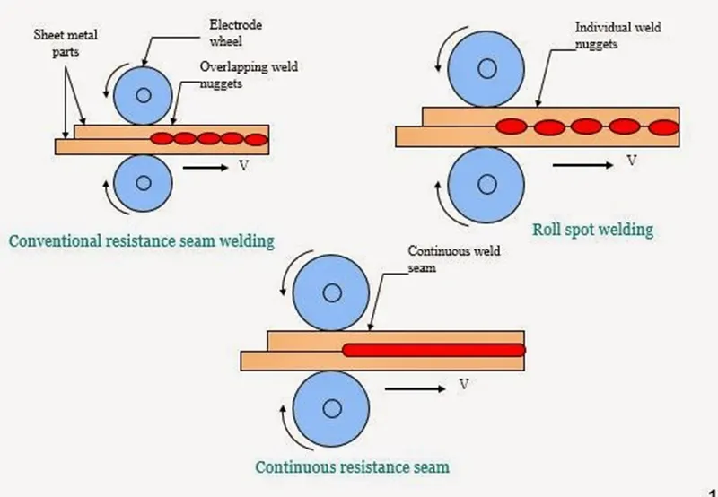
- Resistance Seam Welding is a subset of Resistance Spot Welding using wheel-shaped electrodes to deliver force and welding current to the parts.
- The difference is that the workpiece rolls between the wheel-shaped electrodes while weld current is applied.
- Depending on the particular weld current and weld time settings, the welds created may be overlapping, forming a complete welded seam, or may simply be individual spot welds at defined intervals.
Spot Welding
Seam Welding
Projection Welding
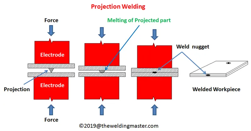
- Like other Resistance Welding Processes, Projection Welding uses heat generated by resistance to the flow of welding current, as well as force to push the workpieces together, applied over a defined period of time.
- Projection Welding localizes the welds at predetermined points by using projections, embossments or intersections, all of which focus heat generation at the point of contact.
- Once the weld current generates sufficient resistance at the point of contact, the projections collapse, forming the weld nugget.
- Solid Projections are often used when welding fasteners to parts.
- Embossments are often used when joining sheet or plate material.
- An example of Projection Welding using material Intersections is cross-wire welding.
- In this case the intersection of the wires themselves localizes heat generation, and therefore resistance.
- The wires set-down into one another, forming a weld nugget in the process.
Flash Welding
- Like other Resistance Welding Processes, Flash Welding uses heat generated by resistance to the flow of welding current, as well as force to push the workpieces together, applied over a defined period of time.
- Flash Welding is a Resistance Welding Process which generates resistance using flashing action.
- This action is created using very high current density at very small contact points between the workpieces.
- At a predetermined point after the flashing process has begun, force is applied to the workpiece, and they are moved together at a controlled rate.
- Rapid upset created by this force expels oxides and impurities from the weld.

Upset Welding
- Like other Resistance Welding Processes, Upset Welding uses heat generated by resistance to the flow of welding current, as well as force to push the workpieces together, applied over a defined period of time.
- While similar to Flash Welding, in Upset Welding the workpieces are already in firm contact with one another, so no flashing occurs.
- Pressure is applied before the current is started, and is maintained until the process is complete.
4) What is Fusion Welding and types of fusion welding with its application in the automotive sector?
- Fusion welding is a process that uses heat to join or fuse two or more materials by heating them to melting point.
- The process may or may not require the use a filler material.
- External application of pressure is not required for fusion welding processes, except for resistance welding, where substantial contact pressure is required during welding for sound joining.
- Fusion welding processes can be grouped according to the source of the heat, for example, electric arc, gas, electrical resistance and high energy.
- These processes include:
- Arc Welding Processes- with the most common process being
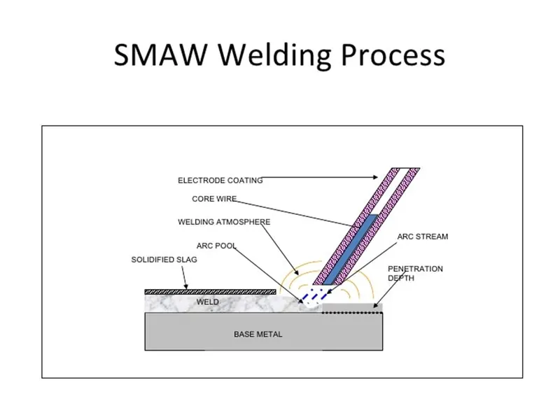
SHIELDED METAL ARC WELDING (SMAW)
- Shielded metal arc welding (SMAW), also known as manual metal arc welding (MMA or MMAW), flux shielded arc welding or informally as stick welding, is a manual arc welding process that uses a consumable electrode covered with a flux to lay the weld.
- An electric current, in the form of either alternating current or direct current from a welding power supply, is used to form an electric arc between the electrode and the metals to be joined.
- The workpiece and the electrode melts forming a pool of molten metal (weld pool) that cools to form a joint.
- As the weld is laid, the flux coating of the electrode disintegrates, giving off vapors that serve as a shielding gas and providing a layer of slag, both of which protect the weld area from atmospheric contamination.
- Because of the versatility of the process and the simplicity of its equipment and operation, shielded metal arc welding is one of the world's first and most popular welding processes.
- It dominates other welding processes in the maintenance and repair industry, and though flux-cored arc welding is growing in popularity, SMAW continues to be used extensively in the construction of heavy steel structures and in industrial fabrication.
- The process is used primarily to weld iron and steels (including stainless steel) but aluminium, nickel and copper alloys can also be welded with this method.
- Shielded metal arc welding (SMAW), also known as manual metal arc welding (MMA or MMAW), flux shielded arc welding or stick welding. Suitable for welding ferrous and non-ferrous materials in all positions.
METAL INERT GAS
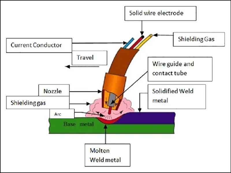
- Metal Inert Gas (MIG) welding is an arc weldingprocess that uses a continuous solid wire electrode heated and fed into the weld pool from a welding gun.
- The two base materials are melted together forming a join.
- The gun feeds a shielding gas alongside the electrode helping protect the weld pool from airborne contaminants.
- Metal Inert Gas (MIG) welding was first patented in the USA in 1949 for welding aluminium.
- The arc and weld pool formed using a bare wire electrode was protected by helium gas, readily available at that time.
- From about 1952, the process became popular in the UK for welding aluminium using argon as the shielding gas, and for carbon steels using CO2. CO2and argon-CO2 mixtures are known as metal active gas (MAG) processes.
- MIG is an attractive alternative to MMA, offering high deposition rates and high productivity.
- MIG/MAG welding is a versatile technique suitable for both thin sheet and thick section components.
- An arc is struck between the end of a wire electrode and the workpiece, melting both of them to form a weld pool.
- The wire serves as both heat source (via the arc at the wire tip) and filler metal for the welding joint.
- The wire is fed through a copper contact tube (contact tip) which conducts welding current into the wire.
- The weld pool is protected from the surrounding atmosphere by a shielding gas fed through a nozzle surrounding the wire.
- Shielding gas selection depends on the material being welded and the application. The wire is fed from a reel by a motor drive, and the welder moves the welding torch along the joint line.
- Wires may be solid (simple drawn wires), or cored (composites formed from a metal sheath with a powdered flux or metal filling).
- Consumables are generally competitively priced compared with those for other processes. The process offers high productivity, as the wire is continuously fed.
- Manual MIG/MAG welding is often referred as a semi-automatic process, as the wire feed rate and arc length are controlled by the power source, but the travel speed and wire position are under manual control.
- The process can also be mechanised when all the process parameters are not directly controlled by a welder, but might still require manual adjustment during welding. When no manual intervention is needed during welding, the process can be referred to as automatic.
- The process usually operates with the wire positively charged and connected to a power source delivering a constant voltage. Selection of wire diameter (usually between 0.6 and 1.6mm) and wire feed speed determine the welding current, as the burn-off rate of the wire will form an equilibrium with the feed speed.
TUNGSTEN INERT GAS
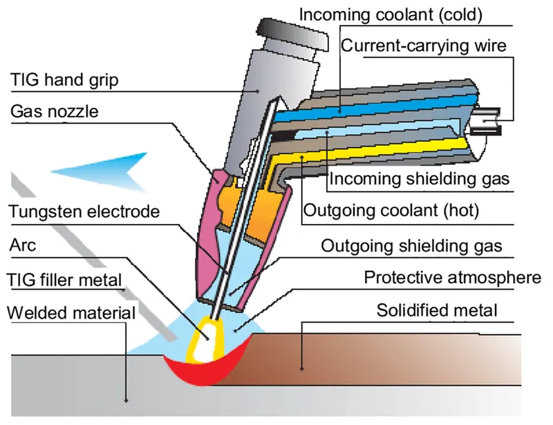
- Tungsten Inert Gas (TIG) welding, also known as Gas Tungsten Arc Welding (GTAW) is an arc welding process that produces the weld with a non-consumable tungsten electrode.
- Tungsten inert gas (TIG) welding became an overnight success in the 1940s for joining magnesium and aluminium.
- Using an inert gas shield instead of a slag to protect the weldpool, the process was a highly attractive replacement for gas and manual metal arc welding.
- TIG has played a major role in the acceptance of aluminium for high quality weldingand structural applications.
- A constant current welding power supply produces electrical energy, which is conducted across the arc through a column of highly ionized gas and metal vapors known as plasma.
- GTAW is most commonly used to weld thin sections of stainless steel and non-ferrous metals such as aluminium.
PLASMA ARC WELDING
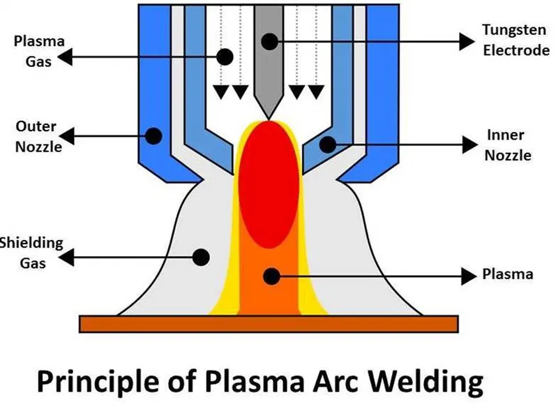
- Plasma arc welding (PAW) is an arc welding process very similar to TIG welding as the arc is formed between a pointed tungsten electrode and the workpiece.
- However, by positioning the electrode within the body of the torch, the plasma arc can be separated from the shielding gas envelope.
- The electric arc ionizes the gas (usually argon) in the chamber creating what is called a “Plasma”.
- Plasma is then forced through a fine-bore copper nozzle which constricts the arc.
AUTOMOBILE APPLICATION OF ARC WELDING
- Arc welding is used to weld the chasis parts in automotive industry.
- Arc welding wire for automotive steel sheets.
- Solid wires suitable for robot welding that generate comparatively small amounts of slag and fume are chosen for welding of automotive parts.
- Arc welding is used to weld the body parts in automotive industry.
- Low heat input welding of thin steel sheets.
- Prevention of burn- through due to excessive heat inputs is important in the welding of car body parts of thin sheets.
- For this reason, thin welding wire with a diameter of 0.9mm, which enables stable welding at low currents and low-heat-input welding power sources.
- TIG welding is used to join the stainless-steel parts & various piping parts in automobile industry.
- MIG welding is used for the repairing work in automobile industry whether they are small, big, light or heavy.
5) What is the 3-2-1 Principle?
3-2-1 PRINCIPLE
- The 3-2-1 principle of location (six point location principle) is used to constrain the movement of workpiece along the three axes XX, YY, and ZZ.
- This is achieved by providing six locating points, 3 pins in base plate, 2 pins in vertical plane and 1 pin in a plane which is perpendicular to first two planes.
- Accurately locating of not just one part, but each and every part that is loaded into the fixture is crucial.
- Any variation in part location on the fixture adds to the dimensional tolerance that must be assigned to the finished parts.
- Additionally, the method of supporting and securing the part in the fixture affects not only dimensional tolerances, but surface finishes as well.
- This is true because improper supporting or clamping can temporarily or permanently deform the part.
- Techniques for supporting and clamping must be considered together with the method of locating in order to assure repeatability from part-to-part.
- Locating of a part to be machined is a three-part process:
- Supporting
- Locating (Positioning)
- Holding (Clamping)
The Locating Process: Degrees of Freedom
In order to completely specify the position in space of a three-dimensional
object (such as the cube that’s shown), we refer to six coordinates:
- Translational position along the X-axis
- Translational position along the Y-axis
- Translational position along the Z-axis
- Rotational position about the X-axis
- Rotational position about the Y-axis
- Rotational position about the Z-axis
These six coordinates are known as the six degrees of freedom of a three-dimensional object. As the double-headed arrows indicate, the translational and rotational positions can vary in either direction with respect to each of the three axes.
To completely prevent movement, all six degrees of freedom must be restricted.
The Locating Process: 3-2-1 Method
We have two objectives when mounting a part in a fixture for machining:
1. Accurately position the part at the desired coordinates.
2. Restrict all six degrees of freedom so that the part cannot move.
A widely used method of accomplishing these two objectives uses the 3-2-1 principle, so-called because it entails three steps that employ three, then two, then one fixed points of known location. Since that adds up to six fixed points, it’s also known as the six point method.
In the three steps of the 3-2-1 method, three mutually perpendicular planes, called datum planes, are introduced, one at each step. These three planes define the workpiece position, and together with opposing clamping forces fully constrain the part. Let’s take a look at the details of the 3-2-1 method.
First Plane
Geometry tells us that three points are required to define a plane. This is the "3" in 3-2-1. So, three specific points are used to define the first plane. Fewer than three points cannot define a plane, and in the real world dimensional tolerances mean that four or more points will not be coplanar. A real-world, less than ideally perfect part placed on four or more reference points will, in fact, rest on only three of the points due to its less than perfect surface. Different parts may rest on different combinations of three points, resulting in variation between finished parts. A stool can be used to illustrate this concept. A two-legged stool would certainly be unstable. A three-legged stool sits rock-solid. A four-legged stool is often found to rock. In the illustration, a three dimensional part, represented by a cube, is placed on a datum plane defined by three support points. The part’s six degrees of freedom have now been reduced to three. It can still move along the X or Y axes, and it can still be rotated about the Z axis. (The part cannot move along the Z axis because it is held against the plane by clamping force.
TIPS
- Use the largest surface of the part for the first ("primary") reference plane.
- Position the three support points as far apart as possible.
- If more than three support points are required to prevent deflection, make the additional points adjustable.
Second Plane
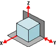
A second plane, if it is perpendicular to the first, can be defined by two points, the "2" in 3-2-1. The part is now constrained to one degree of freedom: movement along the Y axis. (The part cannot move along the X or Z axes because it is held against the planes by clamping force.)
TIPS
- Use the largest surface of the part for the first ("primary") reference plane.
- Position the three support points as far apart as possible.
- If more than three support points are required to prevent deflection, make the additional points adjustable.
Third Plane
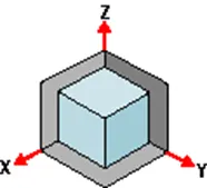
A third plane, if it is perpendicular to both of the first two planes, can be defined by one point, the "1" in 3-2-1. The part is now entirely constrained. It cannot move along or rotate about the X, Y, or Z axes. (Remember that the part is held against each of the three planes by clamping force.)
TIPS
- If more than one support point is required to prevent deflection, make the additional points adjustable.
Machined is Best
It’s best if the workpiece surfaces intended to contact the support points are machined. Cast surfaces are usable, but then tend to create tolerance problems. Machined holes are the number one choice. Two machined holes can be used to eliminate all but one degree of freedom.
Repeatability
Repeatability is a paramount concern. It means that each part should be nearly identical to each other part coming off the same fixture. "Nearly identical" actually has a specific, quantifiable meaning: key dimensions of all parts produced on the same fixture must fall within defined tolerances.
In order to stay within tolerances, it’s best if the workpiece surfaces intended to contact the support points are machined. Cast surfaces are usable, but they tend to create tolerance problems. Machined holes are the number one choice, because two machined holes can be used to eliminate all but one degree of freedom.
The next best feature to use for consistent locating is machined surfaces at right angles. The "machined surface" desired here can simply be a tab or small flat specifically included for locating purposes.
Repeatability is achieved through application of the 3-2-1 method to the three aspects of the locating process:
1. Supporting
2. Locating (positioning)
3. Holding
Supporting
- The part is supported from "below" with reference to the Z axis. (Introduction of the first reference plane.)
- Gravity positions the part against the support locator.
- Provide adjustable auxiliary support points as needed to prevent deflection.
- Vertical location with respect to the fixture is now established
- The part is positioned horizontally, in the X-Y plane. (Introduction of the second and third reference planes.)
Holding
- The part is clamped against fixed locators. Therefore, a known and unvarying position of the part is maintained with respect to the X, Y, and Z axes.
- One strap clamp or clamp arm will restrict the workpiece in three dimensions due to friction between the workpiece and clamp. However, friction alone may not be enough to prevent the workpiece from moving during machining.
- Cutting forces will not move a properly supported and clamped part.
Locating
- The part is positioned horizontally, in the X-Y plane. (Introduction of the second and third reference planes).
Summary: Clamping Rules of Thumb
- Define three reference planes on the workpiece and fixture.
- Provide one opposing clamping force opposite each plane to restrict movement.
- When in doubt, rely on additional cylinders to take up uncertainty.
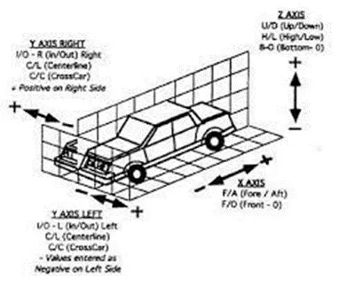
6) Define Body Coordinate system?
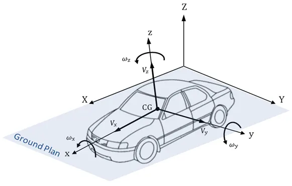
- Coordinate system is a reference system consisting of a set of point, lines & surfaces used to define position of point in space either in 2 or 3 dimensions.
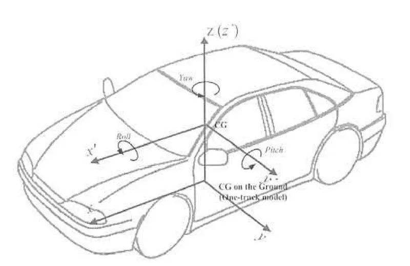
- In general BCS is also called as car line or body line
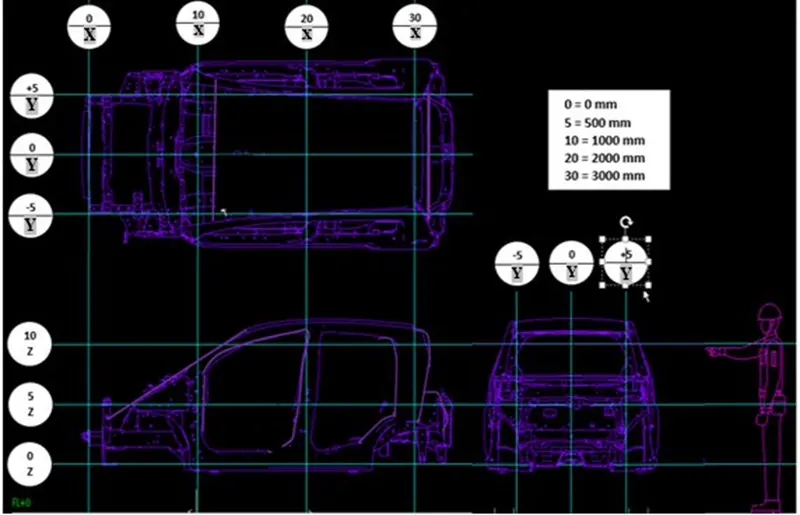
- Car lines are the (Grid lines) shown on the fixture , which virtually represent the same location in the BIW. All the car line on fixture display the coordinate at corner for reference . With these lines one can easily relate the ,location in BIW.
- Some times single coordinate hole is given in the fixture ,that also represent the car line coordinates, from that reference point fixture is made and can be inspected . Body coordinate are mentioned near the hole
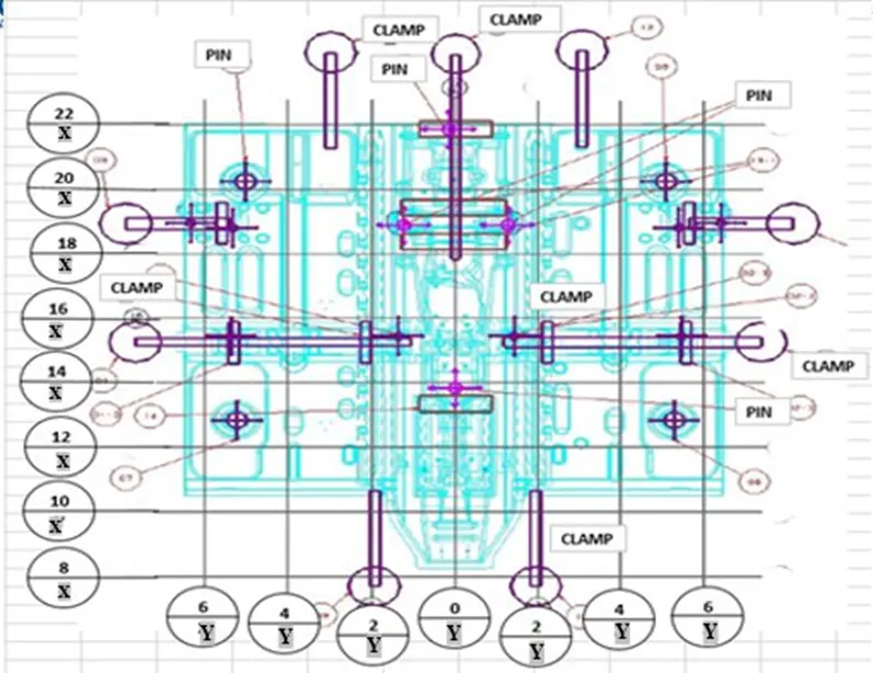
Grid Line on the fixture
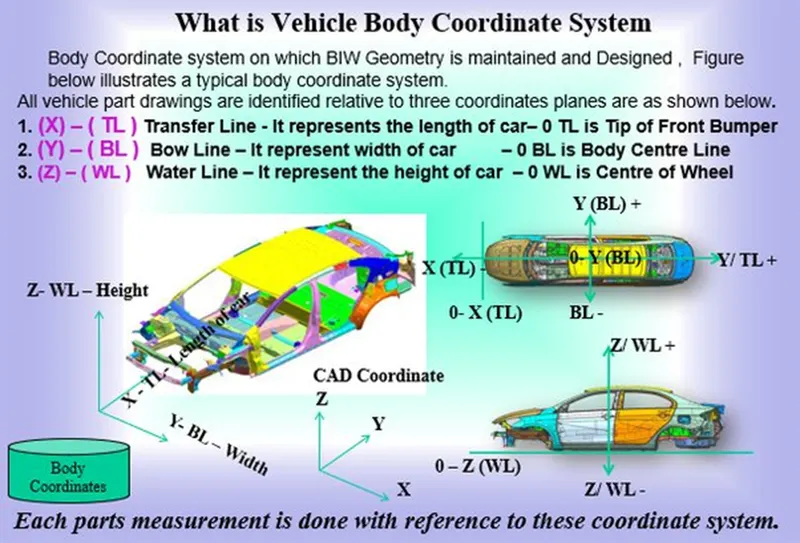
Vehicle Body Coordinate System
Maintaining X,Y & Z co-ordinates in fixture is a very important factor.
We should try that the co-ordinates of locating and clamping points should not be in three decimal (e.g. X=100.124, Y=245.127, Z=450.458).
They should be in the whole nos. or max upto 1 decimal . Once these co-ordinates are maintained automatically the BIW base structure is maintained.
All vehicle product drawings are identified numerically relative to three vehicle planes Description shown below.
- (X) It is in length of BIW – 0 Xis Near Front Bumper
2, (Y) It is in width of BIW – 0 Y - is Body Center Line
- (Z) It is in Height of BIW - 0Zis about Center of Wheel
7) Elaborate Body Plane System and its essentials.
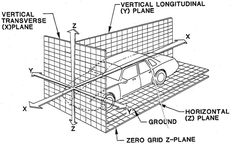
- Body Planes are three mutually perpendicular imaginary planes.
- These are reference planes in automotive car.
- These are used to define GD & T of all parts in automotive domain.
- The measurement from body plane to parts are called body plane dimensions.
Bodylines dimensions are essential for below reason
- It defines exact position of each product in the vehicle with respect to a fixed origin.
- It ensures flawless design for assembly.
- While designing lines, all the designs are carried out relative to the bodylines such as fixtures, Turntables, etc.
- It assist in easy location of different planes in the vehicle.
- It aims in creating a standardized system.
- It assist in quality checks.