The process of project execution activity
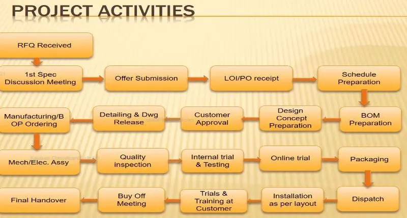
Project execution is about actualizing the already designed plan. It involves putting into action all the activities that were set in the previous processes of the project cycle. The project activities are done according to the set plans, sequence, and procedures to satisfy the requirements of the project.
The types of joining processes
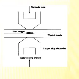
Resistance welding is a welding technology widely used in the manufacturing industry for joining metal sheets and components.
The weld is made by conducting a strong current through the metal combination to heat up and finally melt the metals at localized point(s) predetermined by the design of the electrodes and/or the workpieces to be welded. A force is always applied before, during, and after the application of current to confine the contact area at the weld interfaces and, in some applications, to forge the workpieces.
Type of resistance welding
Resistance spot welding
Resistance seam welding
Resistance projection welding
Resistance spot welding
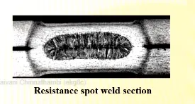
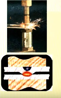
The process is used for joining sheet materials and uses shaped copper-chromium or zirconium alloy electrodes to apply pressure and convey the electrical current through the workpieces. Heat is developed mainly at the interface between two sheets, eventually causing the material being welded to melt, forming a molten Au 21 pool, the weld nugget.
The molten pool is contained by the pressure applied by the electrode tip and the surrounding solid metal
Advantage:
Short weld time and hence high weld speed
Highly adaptable to automation and robotic techniques.
Typical BIW contains 5000 welds
Strength and durability of automobile largely depends on the quality of RSW
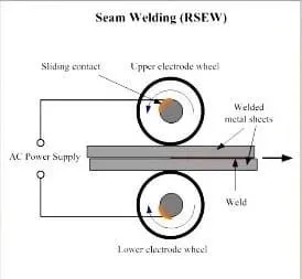
Seam welding is a resistance welding process for joining metal sheets in continuous, often leak-tight, seam joints by directly applying opposing forces with electrodes consisting of rotary wheels.
The current and the heat generation are localized by the peripheral shapes of the electrode wheels.
Application :
Seam welding is mostly applied in the manufacturing of containers, radiators and heat exchangers, etc.
Resistance projection welding
Projection welding is a resistance welding process for joining metal components or sheets with embossments by directly applying opposing forces with electrodes specially designed to fit the shapes of the workpieces. The current and the heat generation are localized by the shape of the workpieces either with their natural shape or with specially designed projection. Large deformation or collapse will occur in the projection part of the workpieces implying high
Application :
Used for mechanical fixing of autobody structures eg. Weld nuts
Fusion Welding
Fusion welding processes can be grouped according to the source of the heat, for example, electric arc, gas, electrical resistance and high energy.
These processes include:
Arc Welding
The process involves either a consumable or a non-consumable electrode (rod or wire).
An arc is produced between the tip of the electrode and workpiece to be welded, using an AC or a DC power supply.
Types of Arc Welding
Manual metal arc welding
Gas-shielded metal arc welding (Metal inert gas (MIG) welding)
Gas-shielded tungsten arc welding (Tungsten inert gas (TIG) welding)
Submerged arc welding
Plasma arc welding
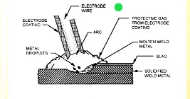
Manual metal arc welding (MMA or MMAW) is also known as Shielded metal arc welding(SMAW), or informally as stick welding.
Stick welding is a process where the arc is struck between the metal rod (electrode flux coated) and the workpiece, both the rod and workpiece surface melt to create a weld.
Gas-shielded metal arc welding
(Metal inert gas (MIG) welding)
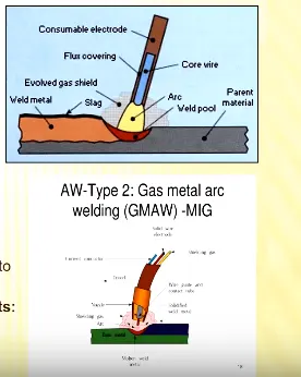
Metal Inert Gas (MIG) Welding is an arc welding technique in which a consumable electrode is used to weld two or more workpieces.
MIG Welding makes use of the following components:
Consumable Electrode
Inert Gas Supply
Welding Head
A.C or D.C Power Supply
Tungsten Inert Gas Welding (TIG Welding), also known as Gas Tungsten Arc Welding (GTAW), is an arc welding method that uses a non-consumable tungsten electrode to weld two or more workpieces. It is very much similar to Metal Inert Gas (MIG) Welding.
The following components are necessary to perform
Tungsten Inert Gas Welding: Gas
Supply
Power supply
Non-Consumable tungsten electrode
Inert Gas Supply Work
Filler rod (depend on the nature of workpiece) Pieces)
Welding Head
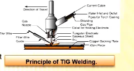
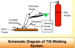
consumable to be added for thicker parts.
Plasma Arc Welding (PAW). This process uses an electric arc created between an electrode and the torch nozzle. The electric arc ionizes the gas (usually argon) in the chamber creating what is called a 'plasma.' It is then forced through a fine bore copper nozzle that constricts the arc and directs it to the workpiece, allowing the plasma arc to be separated from the shielding gas (which is usually made from a mixture of argon and hydrogen).
Submerged Arc Welding (SAW). This frequently-used arc welding process uses a continuously fed consumable electrode and a blanket of fusible flux which becomes conductive when molten and provides a current path between the workpiece and the electrode. The flux also prevents spatter and sparks while suppressing ultraviolet radiation and fumes.
Flux Cored Arc Welding (FCAW). Developed as an alternative to SMAW, this process uses a continuously fed consumable electrode with a flux and a constant voltage or constant current power supply. Sometimes using a shielding gas this process can also just use the flux to provide protection from the atmosphere.
Mechanical Fastening
The joining of material combinations which cannot be easily welded such as pre-painted steels or very dissimilar metals
Ex: Al application in the auto body make use of mechanical fastening techniques to overcome the poor inherent weldability of Al.
The joining of materials in applications where high fatigue life is critical compared to static strength
The joining of materials where long tool life is of relative importance Screws and bolts
Self-piercing riveting
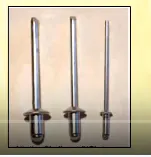
Self-piercing riveting is a high-speed mechanical fastening process for point joining sheet material, typically steels and aluminum alloys. It is a single-step technique, generally using a semi-tubular rivet to clinch the sheets in a mechanical joint. There is also a process variant that utilizes solid rivets. As the name suggests, pre-drilled holes are not required, allowing the joint to be made rapidly in one operation. The process cycle is shown in the cross-section below.
Hemming process
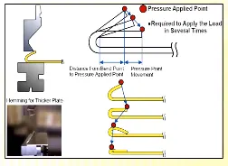
Hemming and seaming are two similar metalworking processes in which a sheet metal edge is rolled over onto itself.
Hemming is the process in which the edge is rolled flush to itself, while a seam joins the edges of two materials.
Adhesive Bonding
Adhesive bonding is used to fasten two surfaces together, usually producing a smooth bond.
This joining technique involves glues, epoxies, or various plastic agents that bond by evaporation of a solvent or by curing a bonding agent with heat, pressure, or time.
3-2-1 principle
Fixtures must correctly locate a workpiece in a given orientation for a cutting tool, measuring device, or component. Locating and clamping are the critical functions of any work holding fixture.
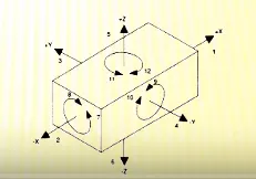
A workpiece free in space can move in an infinite number of directions. This motion can be broken down into twelve directional movements, or "degrees of freedom" for analysis. All twelve degrees of freedom must be restricted to ensure proper referencing of a workpiece.
The best and most cost-effective method of part location is referred to as the 3-2-1 method.
(3.) Minimum: three locator blocks to establish the part plane. Three locators, or supports, are placed under the workpiece. The three locators are usually positioned on the primary locating surface. This restricts one axial movement downward and 4 radial movements. Together, the three locators restrict five degrees of freedom.
(2.) Round locating pin in a round hole that defines the location in four directions (4-way) perpendicular to the plane Previously established. This restricts four axial movement
(1.) Round locating pin in a slot that defines two of the directions of the other pin (2-way). This restricts two axial movements
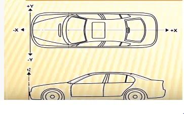
Body coordinate system
The body coordinate system has been widely used in the automotive industry for drawing process design.
A coordinate system is a reference system consisting of a set of points, lines and surfaces. of points in space in either two or three dimensions.
BCS is also called a car line and Body line.
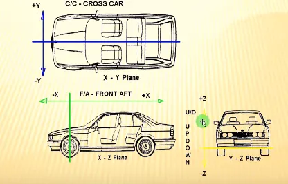
X=Longitudinal direction [(Fore & After - F/A) or (Front O Line - FOL)]
Y=Transverse direction [(Cross car - C/C) or (centerOline - COL)] Z=Vertical direction [(Up & Down - U/D)or (Bottom O Line - BOL)]
The origin of the body coordinate system (OX) is defined at the front center of a vehicle, it indicates the length of the car and the coordinate system (OZ) is below its underbody indicates the height of the car. and the coordinate system (OY) its starting point is the center of the car body indicates the width of the car
Body plane system & its essentials.
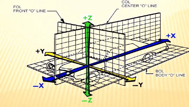
Body planes are the reference planes in an automotive car. These planes are used to define the GD & T of all car parts in the automotive domain.
Body planes are 3 mutually perpendicular imaginary planes. These are generally considered to be present at the Driver position or sometimes at the engine location or at the front end of the car, depending on the customer
The Measurements from the body planes to the parts are called as bodyline dimensions
These body planes are called as
FOL Front "O" Line
COL Centre "O" Line
BOL Body "O" Line
The Measurement along FOL or X-axis is called F/A Front Aft
The Measurement along COL or Y-axis is called as C/C Cross Car
The Measurement along BOL or Z-axis is called as U/DUP Down
Bodyline dimensions are essential for the reasons stated below,
It defines the exact position of each product in the vehicle w.r.t. a fixed origin
It ensures flawless design for assembly
While designing lines, all the designs are carried out relative to the bodyline, viz ., fixtures, turntables, etc .,
It assists in the easy location of different parts in a vehicle
It aims in creating a standardized system
It assists in Quality Checks